The Complete Guide to Flowmeters | What They Are and How They Work?

Introduction
Flow is one of the crucial parameters measured in process industries and water treatment plants, amongst other applications. For example, in water treatment plants where filtration equipment is cleaned periodically, a predetermined volume of water has to be pumped through filters. The GPM(Gallons per minute) value is multiplied by the duration of the cleaning process to measure the amount of water used for cleaning. A similar principle is used for measuring the amount of chemicals such as acids or caustic in a CIP(Clean in place) process. Accurate measurements of these chemicals ensure a successful cleaning operation without damaging equipment.
More often than not, flowmeters use indirect measurement principles to calculate the flow of fluids. In these cases, a change in a physical parameter such as temperature or pressure is measured. This measured change is then used in a formula for calculating the flow of the liquid or gas. Some types of flowmeters, such as rotameters, have a local analog readout but most have a way of sending an electrical signal to a remote location in addition to a digital display.
This guide will cover different types of flowmeters and explore their operating principles. We will discuss costs, suitability, accuracy, challenges associated with other flow measurement methods, and the different types of electrical signals supported by various sensors. Finally, we look at how to interface flowmeters with PLCs.
A basic understanding of the concepts of physics, current, and voltage connections will make it easier to follow along with this guide.
Ultrasonic flowmeters
As the name suggests, ultrasound is used to calculate the velocity of a liquid. The flowmeter then uses the value of the measured velocity and the size of the tube to calculate the volumetric flow of the liquid. The velocity of the liquid is measured in two ways:
- The first is based on the principle of the Doppler effect. Ultrasonic waves at a certain frequency are incident upon the process liquid from an emitter. On the diametrically opposite end of the tube is a receiver that measures the frequency of these waves. The frequency received by the receiver is based on the velocity of the liquid.
- The second type of measurement is based on the difference in time taken for sound to travel upstream and downstream of the liquid. Both the values are used to calculate the velocity of liquid flow.
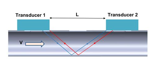
One of the advantages of this type of flowmeter is that it can be installed without any modifications to the tubing. As shown in the picture below, the flowmeter is usually clamped around the tube. Various parameters such as thickness, material, and diameter of the tube are fed into the flowmeter for accurate calculations. However, the disadvantage is that the measurement can be affected by any suspended particles in the liquid or physical variations such as temperature and viscosity.

Thermal flowmeters
A heated probe is inserted into the flowing fluid in this type of flowmeters. The probe loses heat to the liquid, and an electric current is required to maintain the heat at a certain level. This electric current is measured to determine how much heat is being lost. This heat loss increases as the flow of fluid increases. The electric current that is drawn to maintain the heat also increases as a result. The flow rate is calculated by measuring the increase in current. Thermal flowmeters are suitable for measuring the flow rate of gasses but not of liquids.

Magnetic flowmeters
Magnetic flowmeters can only be used to measure the flow rate of conductive liquids such as water. As shown below, when the process liquid flows through a conduit of the flow meter, it is exposed to a magnetic field. An effect similar to Faraday’s law occurs inducing a voltage in the flow meter. The electrodes placed in the flow meter’s walls measure the voltage developed. This induced voltage increases with an increase in the flow. Based on the induced voltage and the size of the tube, the flow rate is calculated by the flow meter.
Differential pressure flowmeters
This type of flowmeter has a constriction in the conduit that causes a change in the pressure of the fluid while passing through the constriction. As the fluid passes through the conduit, the pressure is measured before and after the constriction. This pressure difference is used to calculate the fluid flow. The flow rate is proportional to the square root of the pressure difference.
Differential pressure type flowmeters cause a drop in flow rate. This drop can be either minor or significant depending on the type of flow meter. The advantage of using this type is that they are typically suitable for both liquids and gasses.

Coriolis mass flowmeters
Mass flow meters such as Coriolis mass flow meters are different from the above-mentioned flowmeters because they measure the fluid flow mass per unit time and volume.
There are various types of Coriolis mass flow meters. Process liquid is passed through tubes that are vibrating at the resonant frequency of the pipes. When there is flow in these pipes, it affects how these pipes move. This motion is monitored by sensors and can help determine the mass flow and the density changes if any. The mass flow and density of the process liquid is measured and from that, the volume flow is calculated.
One of the advantages of this type is their accuracy, it is so high that it is almost considered a standard for checking the other flow meters. But, on the other hand, they are expensive and are not suitable for the measurement of gas flow rates.

Rotameter
Rotameters measure the volumetric flow rate of the liquids. These flow meters have a straightforward construction consisting of a glass tube through which the fluid flows and a float. The glass tube is installed vertically, and the liquid flows upwards. The term float can be misleading in this case since the float is not supposed to float in the column of the liquid. The vertical tube has graduations showing the flow rate. As the flow increases the float is lifted up against gravity by the moving liquid, and it falls downwards when the flow decreases. This is the first flow meter I remember seeing at a Zinc manufacturing plant long ago. I was impressed by this flow meter's simple construction and measuring principle.
Because they are relatively inexpensive and easy to maintain, the rotameters are accepted by the manufacturing plants and multi-dwelling residential units. However, one of the disadvantages of rotameters is that they do not have the capability of sending an electrical signal back to the plant, they are meant to be used just for local display.

Wiring and connecting a flowmeter to a PLC
Analog flow sensors can either send a 4-20 mA signal or a 1-5 V DC signal. These signals are hooked up to a PLC input analog module to convert the raw reading into a human-readable value. The flow measurement is used for displaying the flow reading or for a control action such as changing the speed of pumps.
4-20 mA current loops are some of the most common signals in industrial applications. 4 mA corresponds to the lowest value of measurement, and 20 mA corresponds to the highest value. 4 mA is used instead of a 0 mA signal to differentiate between a reading of the lowest value and a broken wire connection. Most PLCs have a built-in 4-20 mA connection or expansion modules that measure 4-20 mA signals.
1-5 V DC signals are also the oldest and widely adopted, just like 4-20 mA signals. This voltage signal can then be wired to a PLC analog input module and the PLC can be programmed to convert the voltage into a flow measurement.

The above picture shows a 1215c AC/DC/Rly Siemens PLC module with two analog inputs. The highlighted area shows how an analog flow sensor can be wired to this PLC module. The circle with ”+” and ”-” represents an analog flow sensor.
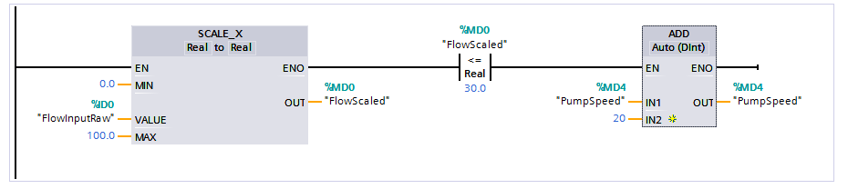
The picture above shows a Siemens code snippet for measuring 4-20 mA or a 1-5 VDC input signal. First, the analog input is scaled to represent an engineering value of 0.0-100.0 flow rate in chosen units. When the scaled level reaches 30.0 or lower, the speed of the pump is increased by a value of 20.

The picture above shows a Siemens PLC 1215c AC/DC/Rly CPU. The highlighted area in orange shows a digital switch connected to the input of the PLC.

The Siemens code snippet above shows how a digital flow sensor can be used to open or close a valve when there is flow in a tube.
In addition to analog modules, PLCs also come with expansion modules for protocols such as RS485, PROFIBUS, and IOLink which are commonly supported by various instruments.
Conclusion
In this tutorial, we have discussed what flow sensors are, why they are a very crucial component in process industries and water treatment plants, and some of the most commonly used types of flow sensors. We have also briefly covered analog & digital wiring connections to PLCs and sample Siemens code snippets to demonstrate how the signals can be scaled and used to control pumps and valves based on flow rate and presence of flow in a tube.