TIA Portal Technology Objects for Siemens Motion Control Systems

Introduction
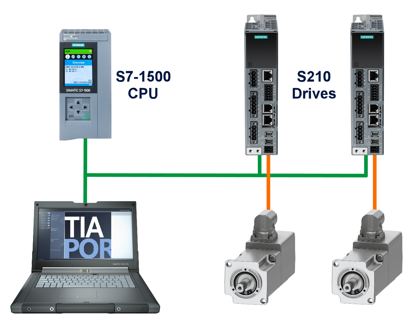
Through PROFINET connectivity, SIMATIC S7-1500 PLCs empower drives to function as positioning, speed, or synchronous axes. TIA Portal provides the means to manage a SINAMICS S210 drive by incorporating a technology object within its software framework, thus enabling its operation through Motion Control instructions execution. In this instance, a dual setup of SINAMICS S210 drives is employed within the application. The initial drive is tasked with position control, acting as the leading axis for the subsequent drive, which operates in synchronous mode. Within this application context, there are two axes in operation: a leading axis referred to as the 'positioning axis' and a following axis identified as the 'synchronous axis,' each fulfilling unique roles within the system.
PLC Hardware Configuration
The following passage offers an intricate breakdown of the setup configurations for the SIMATIC S7-1500 CPU and the SINAMICS S210 when integrated into the TIA Portal interface.
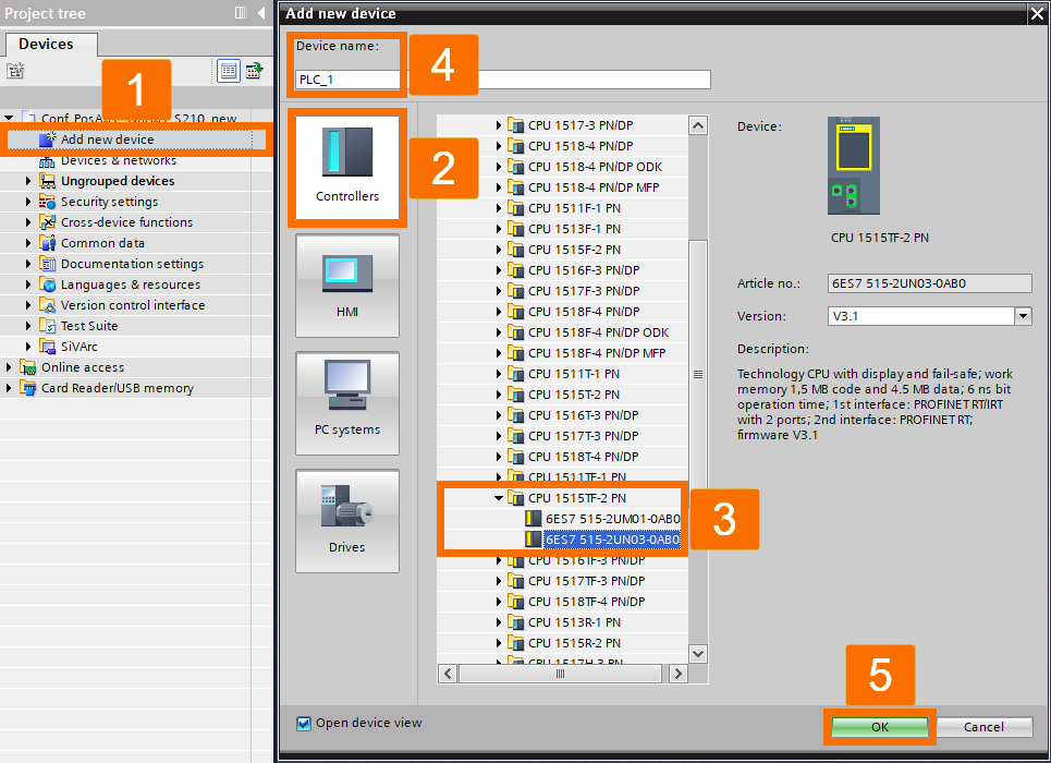
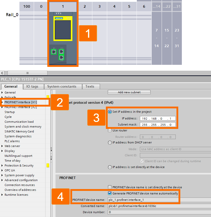
Launch the TIA Portal software and commence a fresh project creation. Navigate to the 'Project View' interface. Browse the hardware catalog to pinpoint and designate the SIMATIC S7-1500 CPU model you intend to employ. Assign the name 'PLC_1' to this CPU and incorporate it into your project configuration. Once the CPU setup is complete, configure security parameters and network preferences accordingly.
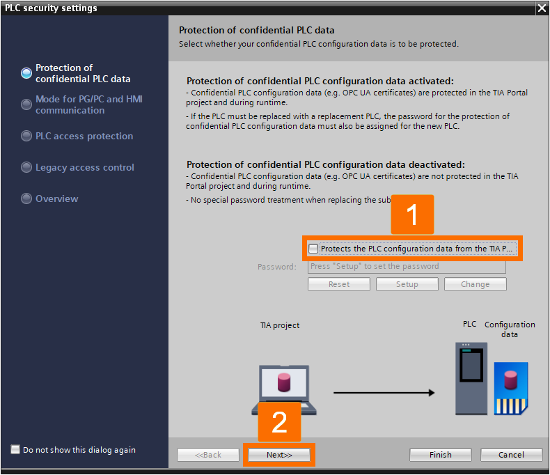
The CPU's creation leads to the Security Wizard's automatic unveiling. Remove the checkmark from the box labeled 'Protects the PLC configuration data' and continue by clicking 'Next.'
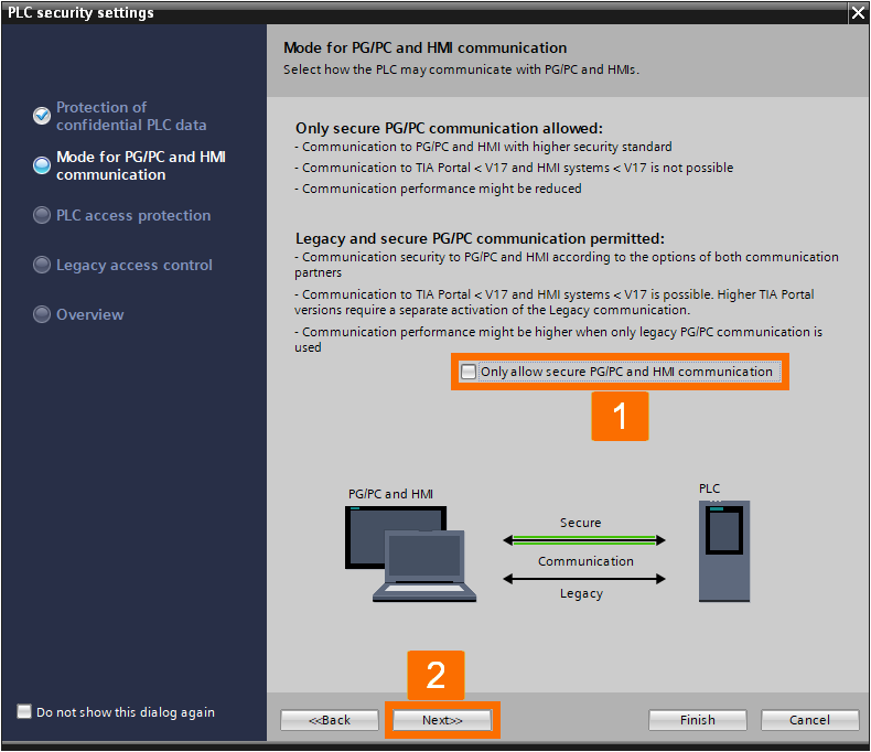
Progress to the next stage by removing the limitation on communication to secure PG/PC and HMI, followed by clicking 'Next.'
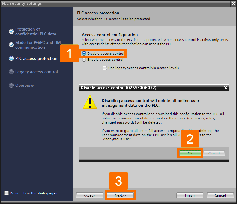
Mark the 'Disable access control' choice, acknowledge the dialog box by pressing OK, then advance by hitting 'Next.'
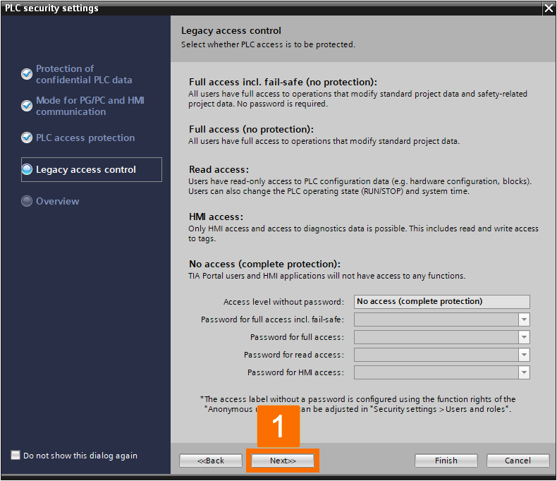
Ensure the validity of 'Legacy access control' and advance by clicking 'Next.'
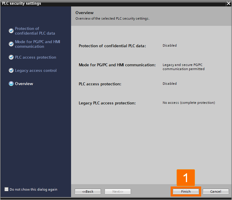
Ensure the arrangement is correct before pressing the 'Finish' button.
Explore the CPU settings and locate the 'Ethernet configurations' from the 'PROFINET interface [X1]' to allocate the IP address. For instance, the provided project utilizes 192.168.0.1 as its IP address and 255.255.255.0 as the subnet mask. Verify that within the PROFINET category, the option labeled 'Generate PROFINET device name automatically' is enabled. This action prompts the software to derive the PROFINET name from the device's designation. The instance project demonstrates the use of the PROFINET label 'plc_1.profinet interface_1.'
Drives Hardware Configuration
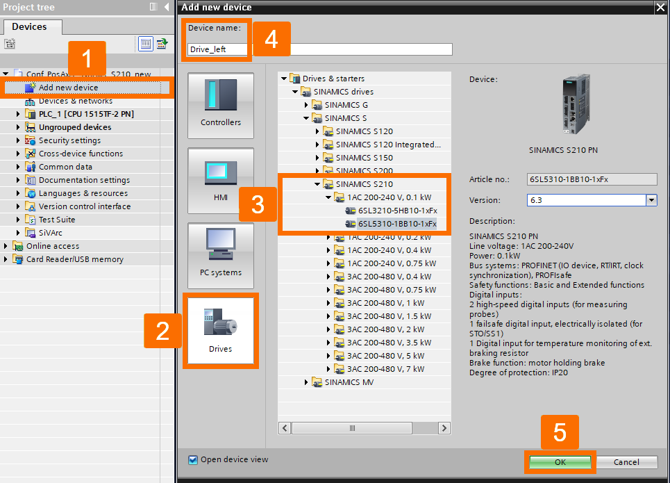
Browse the hardware catalog to identify the SINAMICS drive that fits your requirements, assign the identifier 'Drive_left' to it, and include it in your project setup.
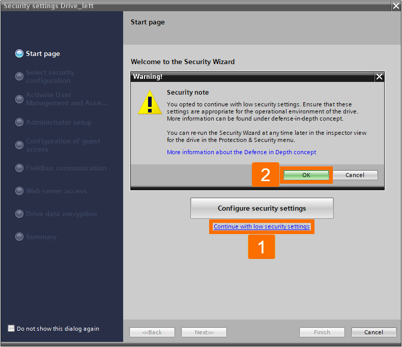
With the completion of drive creation, the Security Wizard will initiate automatically. In the 'Start page' interface, select the option for proceeding with reduced security configurations. Acknowledge the security level alert by choosing OK.
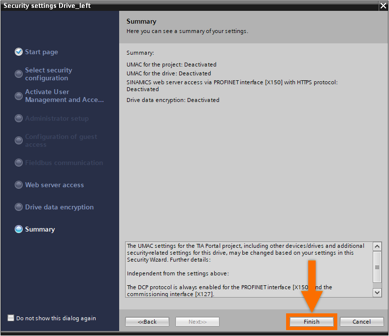
Check the setup details for accuracy, then finalize by selecting 'Finish' in the summary window.
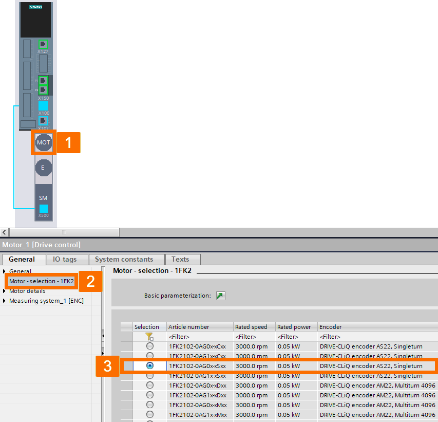
Access the 'Device view' associated with the SINAMICS S210 you have included and double-click on the motor icon (MOT) placed below the converter. Then, within the 'Properties' panel, choose the motor selection section and pick out the motor that corresponds to your needs.
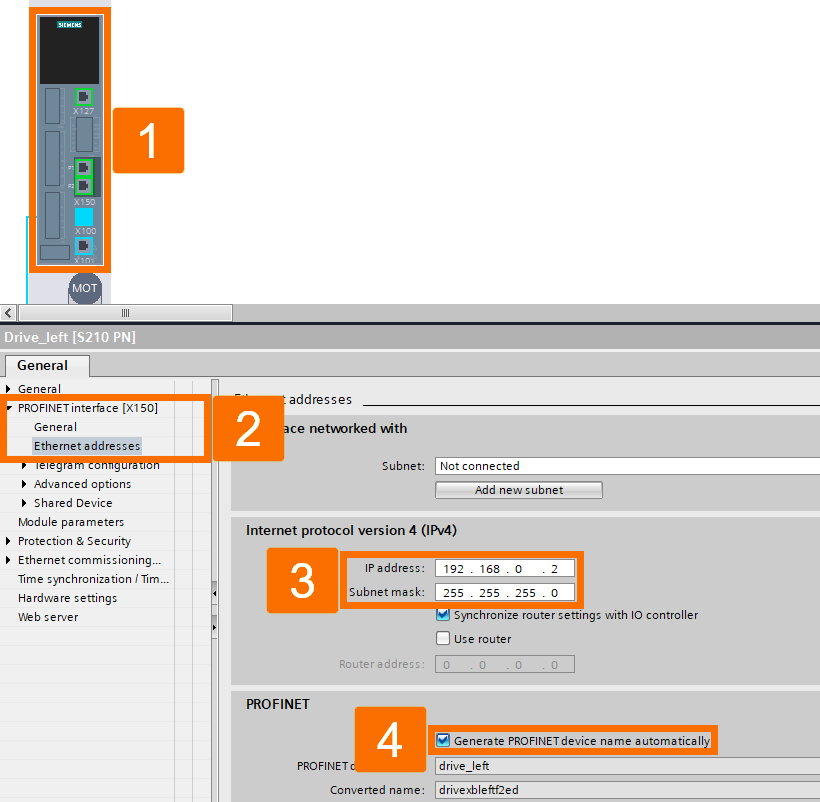
Explore the drive properties to locate the 'Ethernet addresses' section and configure the IP address as needed. In the given project instance, the utilized IP address is 192.168.0.2, accompanied by a subnet mask of 255.255.255.0. Verify that within the PROFINET category, the option labeled 'Generate PROFINET device name automatically' is enabled. The PROFINET system automatically designates the name 'Drive_left' for identification.
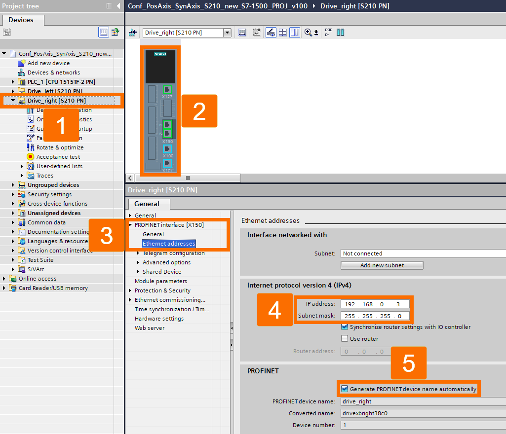
Follow the previously outlined procedure for selecting and setting up the second drive. Set up the network parameters to label the fresh drive as 'Drive_right,' applying 192.168.0.3 as the IP address alongside 255.255.255.0 as the subnet mask.
Connection Settings
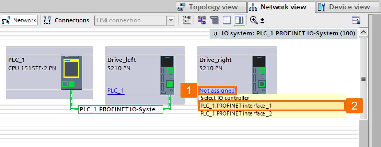
Following the setup of the CPU and drives, your next task is to allocate the PROFINET connections accordingly. Shift over to the 'Network view.' In the station labeled 'Drive_left,' locate the option 'Not assigned,' then opt for 'PLC_1.PROFINET interface_1.'
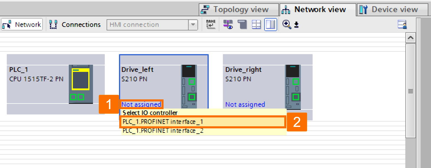
Engage with the 'Drive_right' station by choosing 'Not assigned,' then opt for 'PLC_1.PROFINET interface_1.' Following this event, every station will be interconnected with one another.
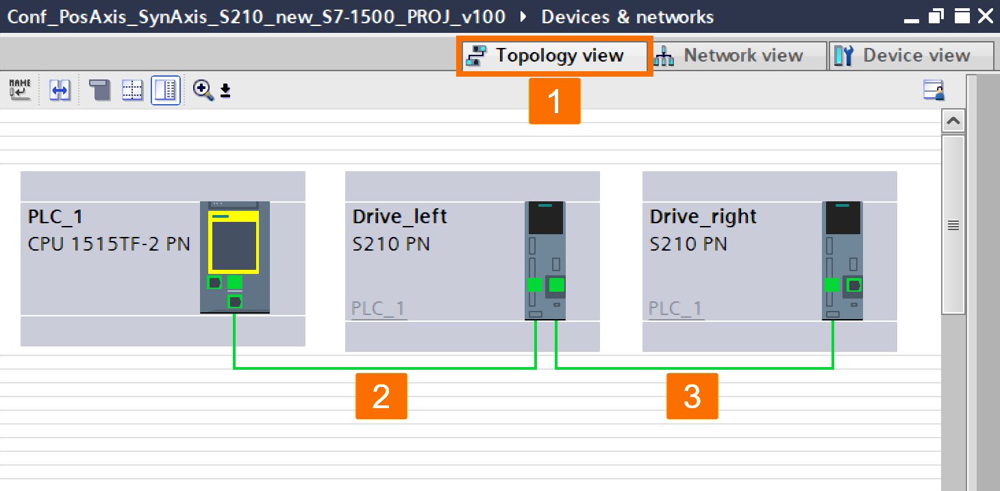
It's essential to adjust the topology of stations to establish an isochronous link between drives and the CPU. Access the 'Topology view.' Use drag-and-drop functionality to create a connection by moving from the upper CPU port to the Drive_left's first port. Utilize the drag-and-drop method to create a link from the Drive_left's second port to the Drive_right's first port.
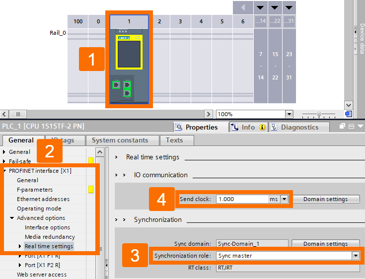
Reach the 'Real-time settings' for the 'PROFINET interface[X1]' by exploring the 'Advanced options' within the CPU's device properties. Arrange the CPU to function as the 'Sync master' and set the 'Send clock' to one millisecond.
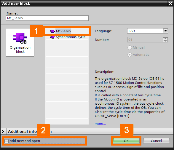
Access the settings of the Drive_left, then locate 'PROFINET interface [X150],' proceed to 'Telegram configuration,' and finally, head to 'Drive control-Telegrams.' Left-click on the ellipsis icon beside the display box titled 'Organization blocks' within the 'Send (Actual value)' area. If the 'MC-Servo' is not found in the list, utilize the 'Create' button.
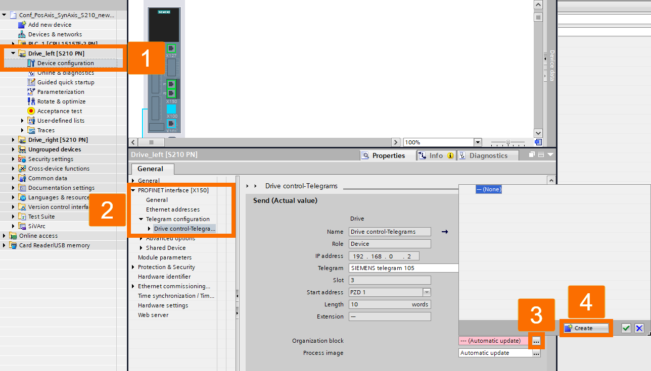
Specifically, select the organizational block designated as 'MC-Servo' within the dialogue box for adding blocks. Remove the checkmark from the 'Add new and open' option and validate your action by clicking OK.
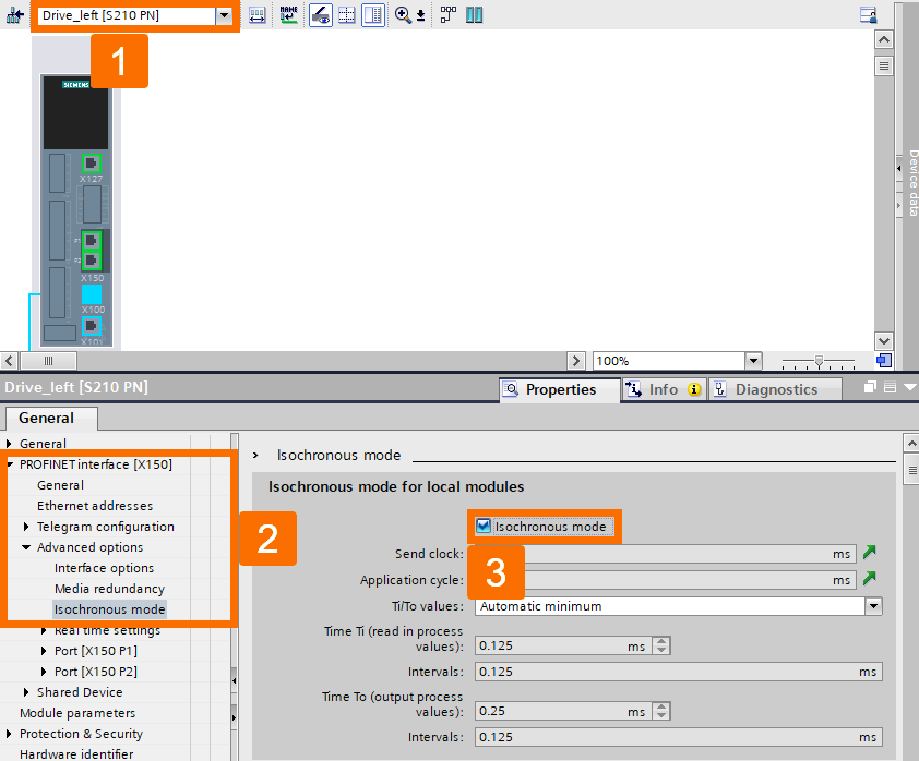
Explore the 'PROFINET interface[X150]' within the Drive_left's device settings, proceed to 'Advanced options,' and verify the status of 'Isochronous mode' to ensure it's enabled.
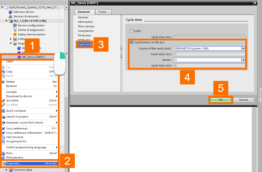
Locate and expand the 'Program blocks' folder within the project tree and right-click over the 'MC-Servo' organization block. Subsequently, opt for the 'Properties' from the displayed menu. Navigate through the module dialog's menu to find the 'Cycle time' option. Toggle the 'Synchronous to the bus' setting and opt for 'PROFINET IO-System (100)' from the dropdown list labeled 'Source of the send clock.' Save your changes by pressing OK.
Repeat the same procedures for the 'Drive_right' as well.
Technology Objects Configuration
For this specific application, the task involves configuring two technology objects: 'positioning' and 'synchronous' axes functioning as the 'leading' and 'following' axes in order.
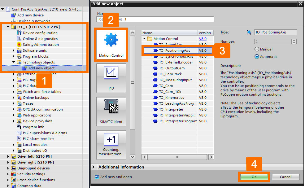
Explore the project tree until you reach 'PLC_1,' then proceed to 'Technology Objects' and double-click over the 'Add new object' option. Choose 'TO_PositioningAxis' from the 'Motion Control' tab. Click OK to proceed.
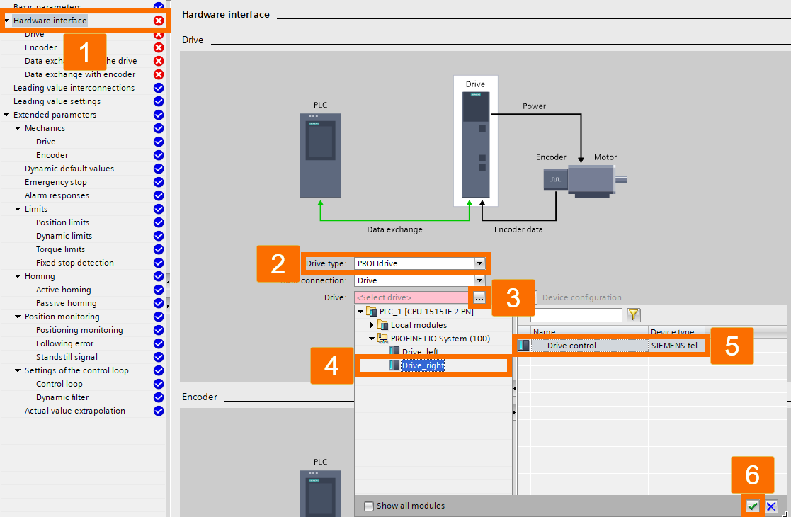
Go to the navigation menu and left-click 'Hardware interface'; proceed to configure 'Drive type' as 'PROFIdrive' and 'Drive' as 'Drive_left.'
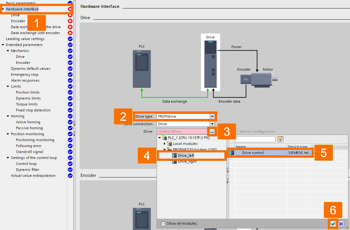
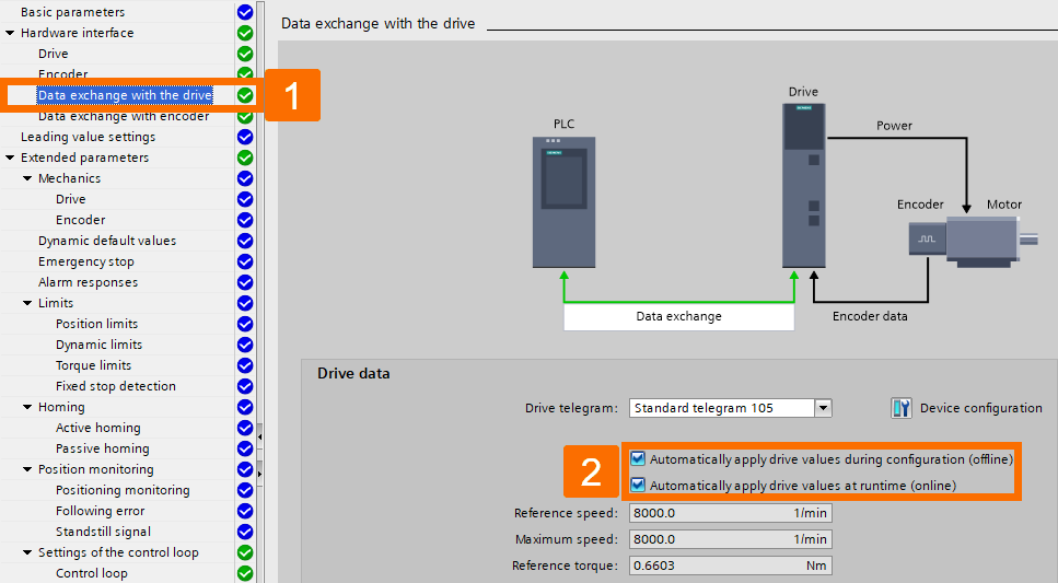
Explore the navigation menu once more and locate the 'Data exchange with the drive' to ensure that automatic data transfer from the drive is enabled. This action guarantees that data from the drive will be transmitted to the 'technology object' automatically.
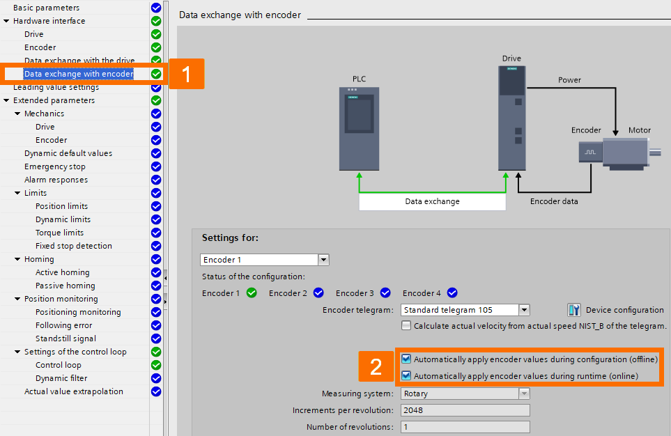
To verify if the data is transmitted from the encoder automatically, access 'Data exchange with the encoder' in the navigation menu and check the status.
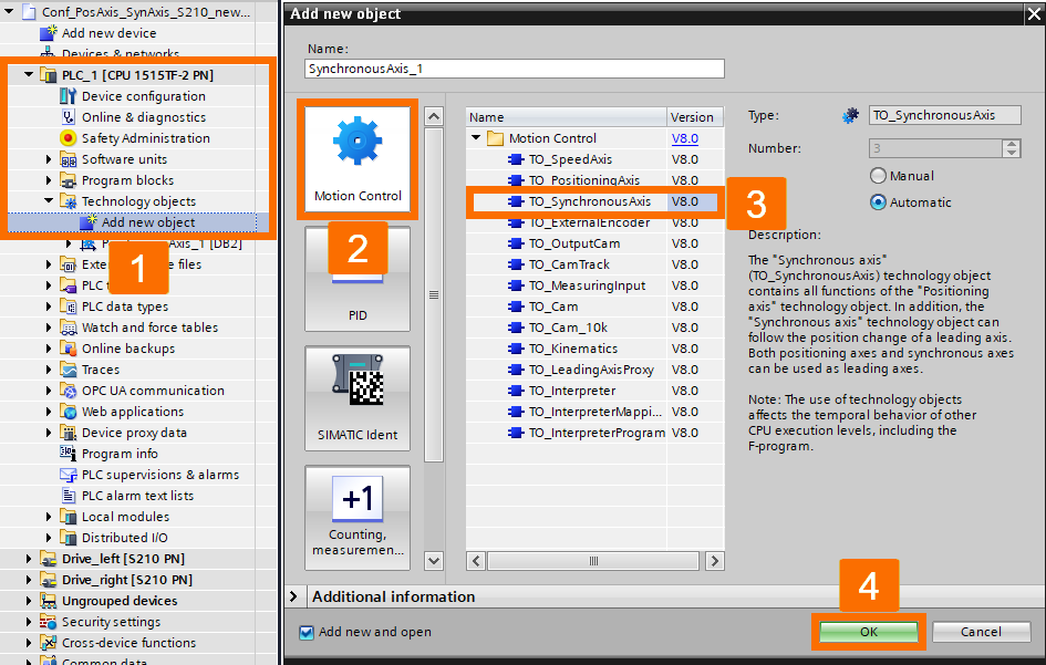
Explore the project tree until you reach 'PLC_1,' then proceed to 'Technology Objects' and double-click over the 'Add new object' option. Choose 'TO_SynchronousAxis' from the 'Motion Control' tab. Click OK to proceed.
Go to the navigation menu and left-click 'Hardware interface'; proceed to configure 'Drive type' as 'PROFIdrive' and 'Drive' as 'Drive_right.'
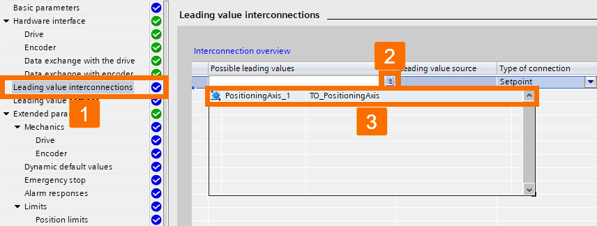
Browse the navigation menu to find the 'Leading value interconnections,' then designate the desired positioning axis within the field of 'Possible leading values.'
Developing TIA Portal Logic
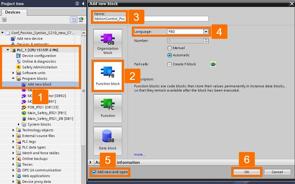
Create a new function block by double-clicking the 'Add new block' item under the 'Program blocks' folder within the 'PLC_1' section. Choose the 'Function block' tab and assign it the name 'MotionControl_Pos.' Ensure the option 'Add new and open' is checked to open the block instantly upon addition. Press OK to include the block.
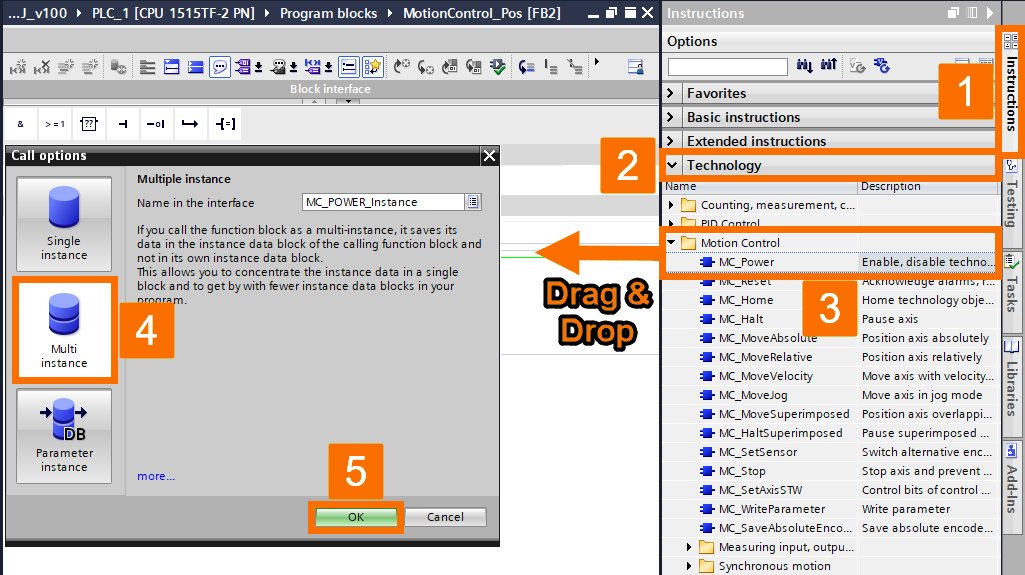
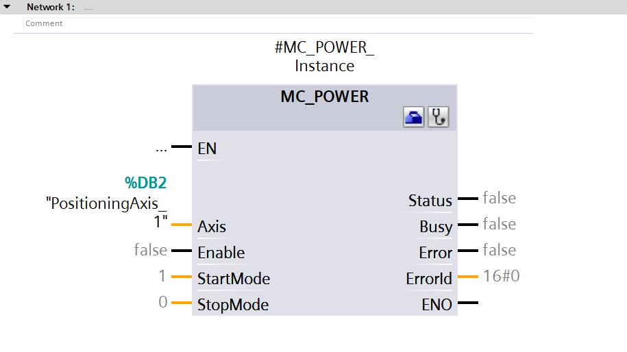
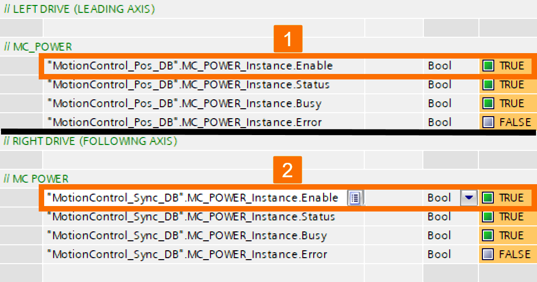
Access the 'Motion Control' directory through the 'Technology' palette within the 'Instructions' task card. Then, drag the 'MC_Power' instruction and drop it to network one. Choose the 'Multi-instance' data block type from the dialog box and proceed by clicking OK to affirm your choice.
Configure the 'MC_Power' instruction as displayed in the picture below.
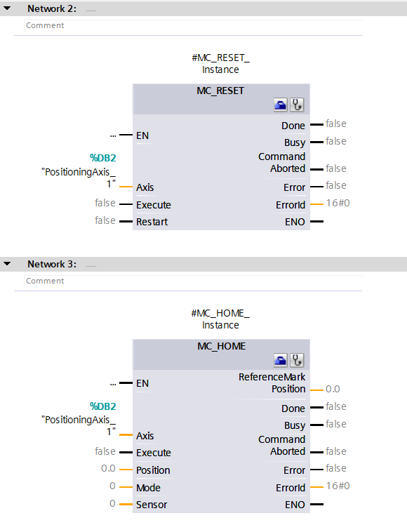
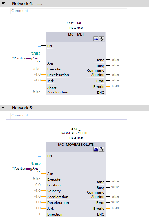
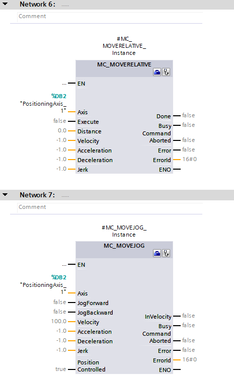
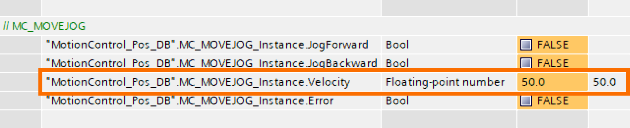
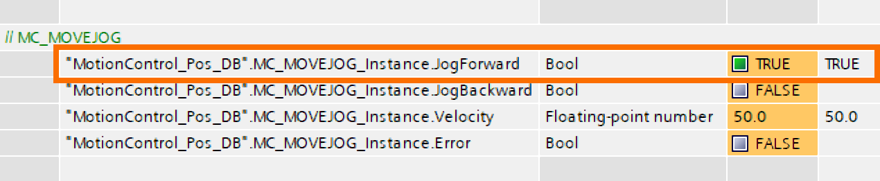
Additionally, include the following instructions through drag-and-drop action into the function block network: MC_Reset, MC_Halt, MC_Home, MC_MoveRelative, MC_MoveAbsolute, and MC_MoveJog. Configure the instructions as displayed in the pictures below.
Create another fresh function block and assign it the name 'MotionControl_Sync.'
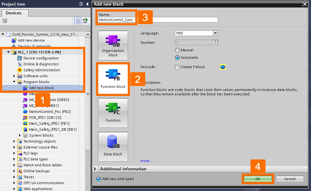
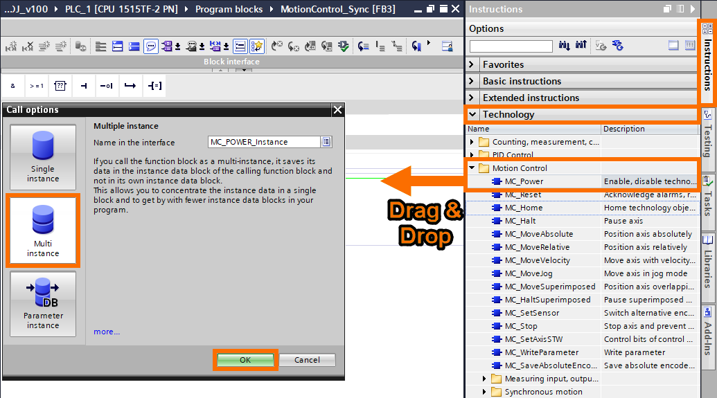
Once again, drag and drop the 'MC_Power' instruction into network one. Choose the 'Multi-instance' data block type and proceed by pressing OK.
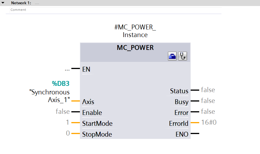
Configure the 'MC_Power' instruction as displayed in the picture below.
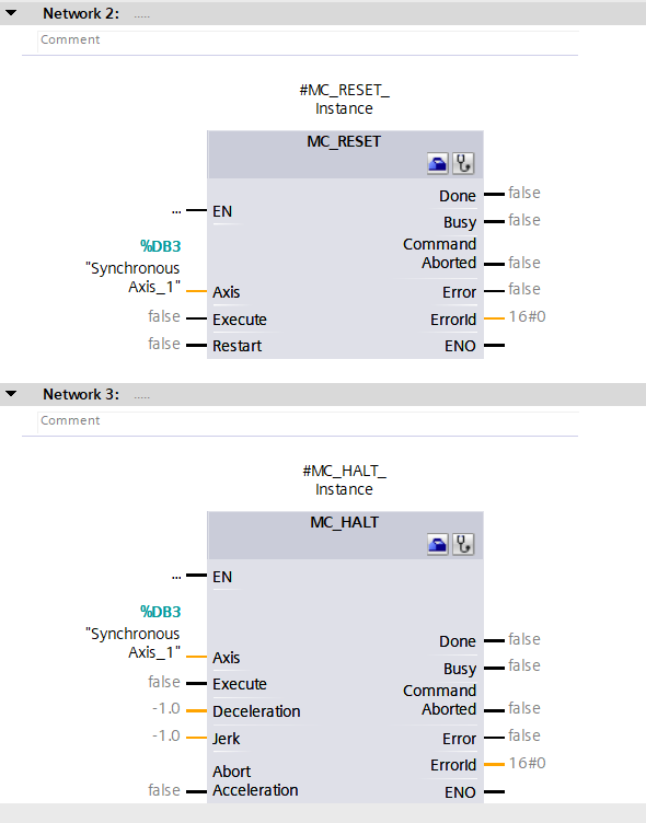
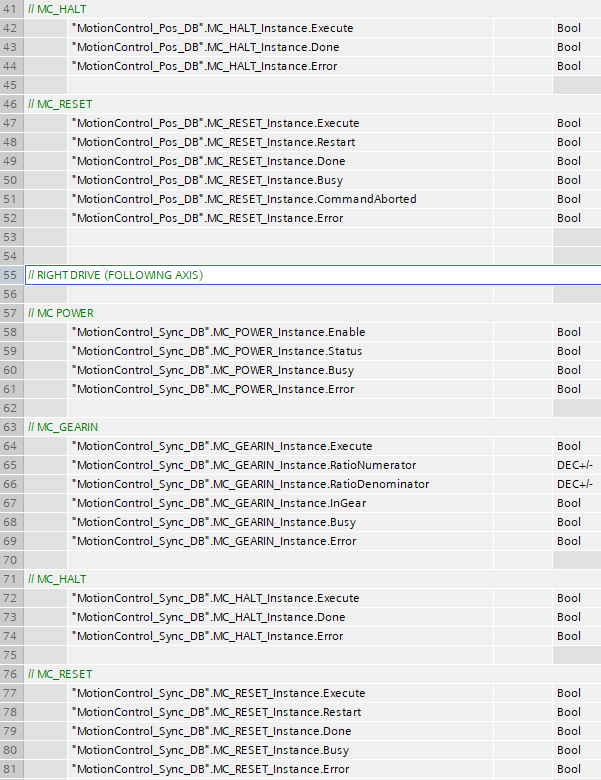
Moreover, include the following instructions in the function block network: MC_Reset and MC_Halt. Configure the instructions as displayed in the picture below.
Access the folder named 'Synchronous motion' and open it. Identify the 'MC_GearIn' instruction and move it to the function block network. Choose the 'Multi-instance' data block type and press OK.
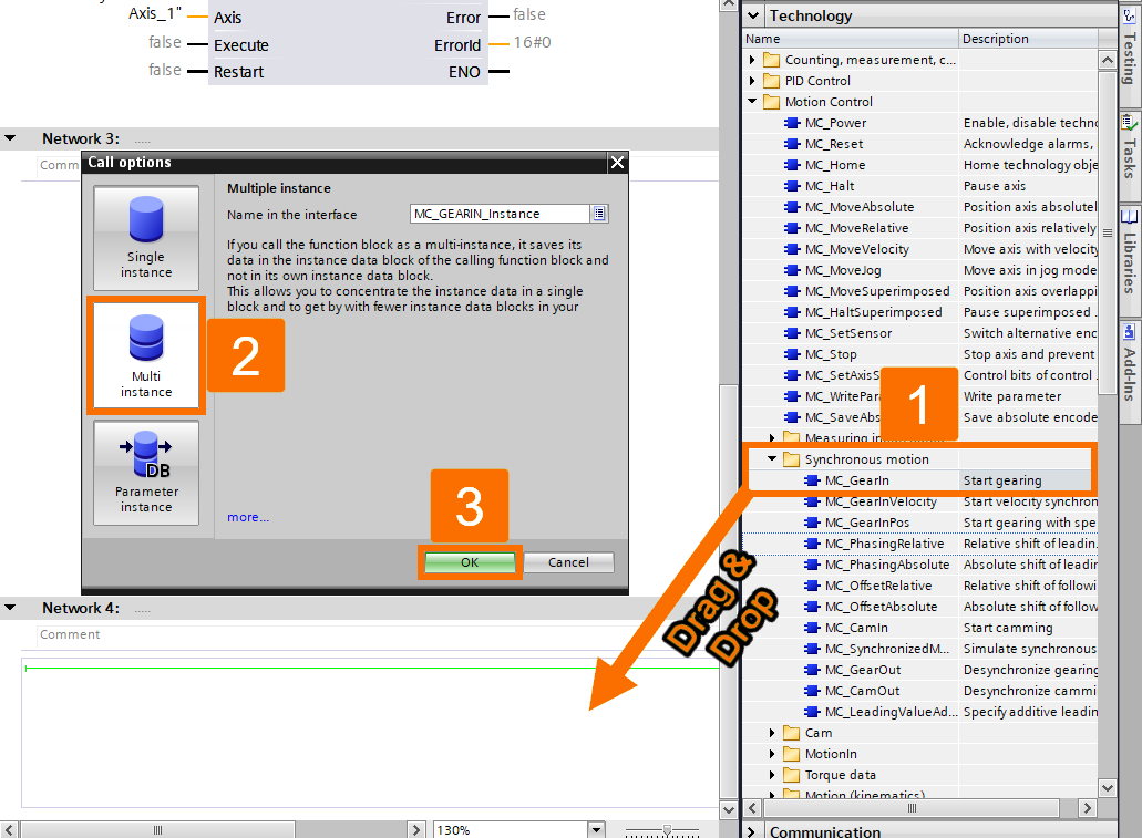
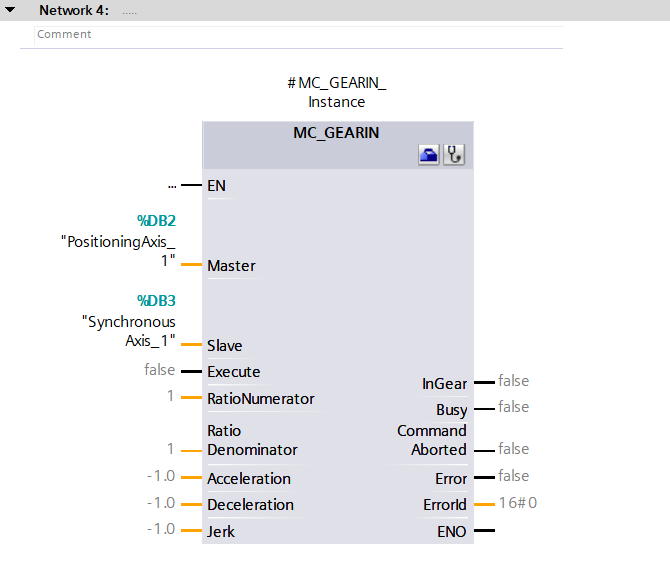
Configure the 'MC_GearIn' instruction as displayed in the picture below.
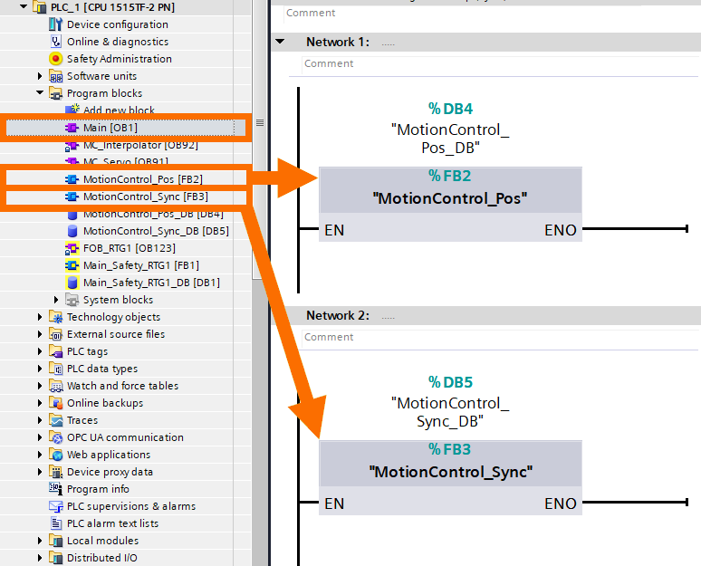
Access the main organization block, which is Main [OB1]. Drag the 'MotionControl_Sync' and 'MotionControl_Pos' function blocks and release them into the OB1 network.
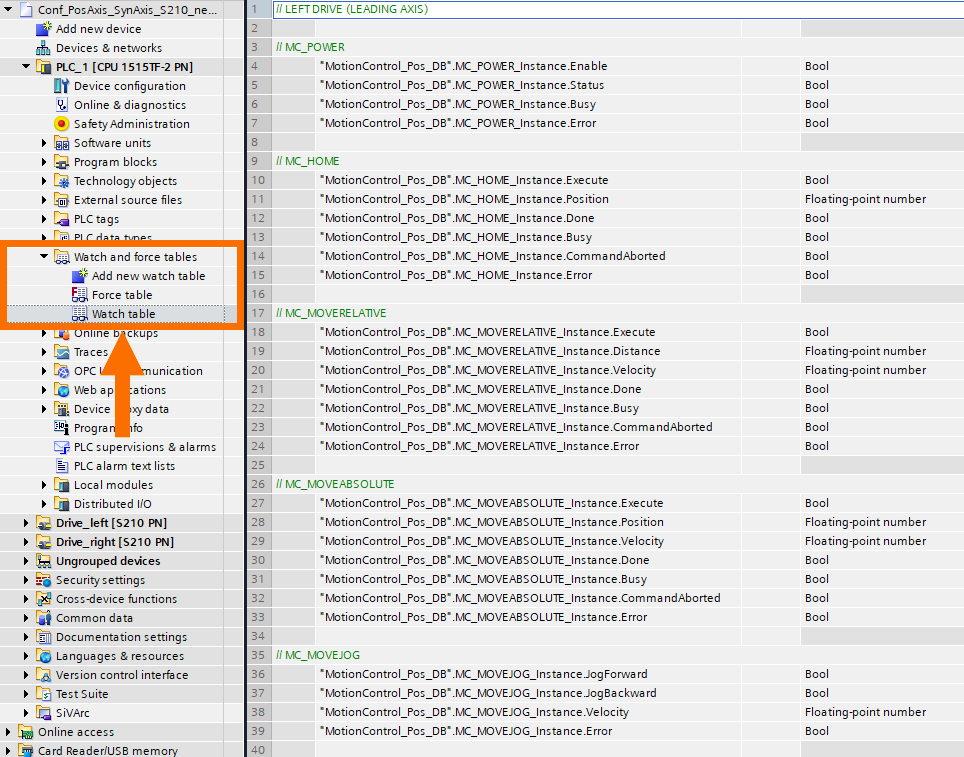
This practical example employs a watch table for overseeing and regulating the drives, as illustrated in the pictures below.
Initializing and Fine-Tuning Performance
Download and transmit the TIA Portal project to the CPU.
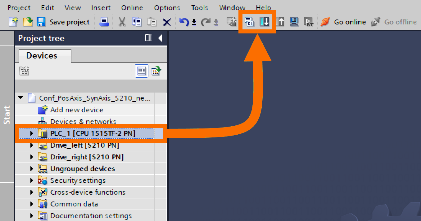
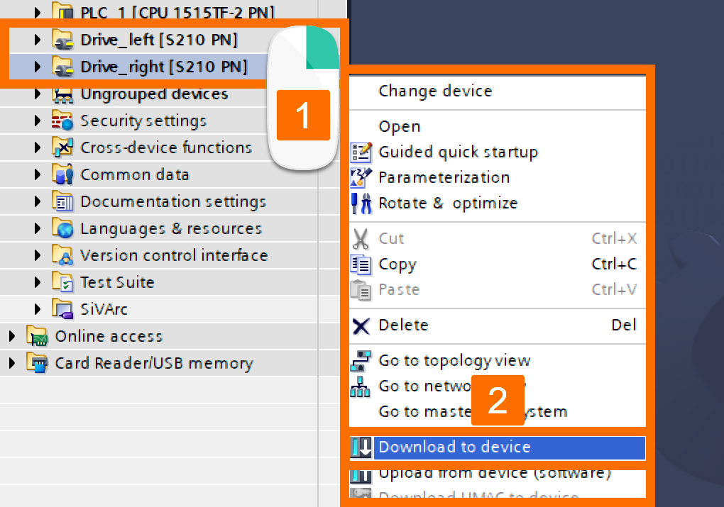
Initiate the parameterization download for the SINAMICS S210 drives. Remember to activate the 'Save parameterization retentively' option to preserve the parameter assignment in the drive's memory.
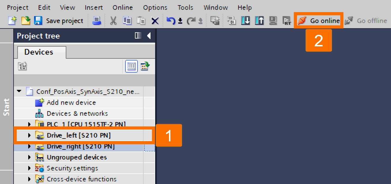
Choose the 'Drive_left' within the project tree and initiate the 'Go Online' action.
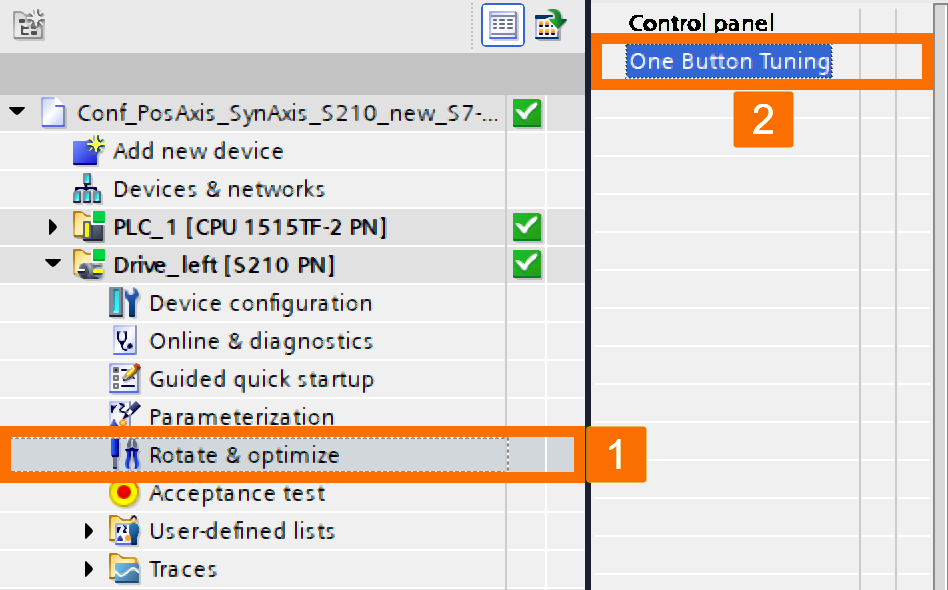
Expand the 'Drive_left' folder and double-click the 'Rotate & optimize' item. Navigate through the workspace menu and select 'One Button Tuning.'
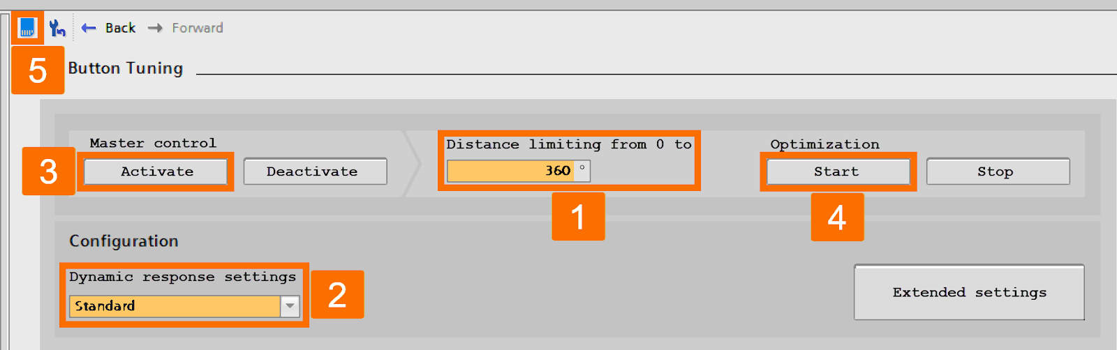
Choose the preferred dynamic configuration and path restriction when fine-tuning, followed by pressing the 'Activate' button. Then, press the 'Start' button to kickstart 'One Button Tuning.' Next, keep the values stored on the drive.
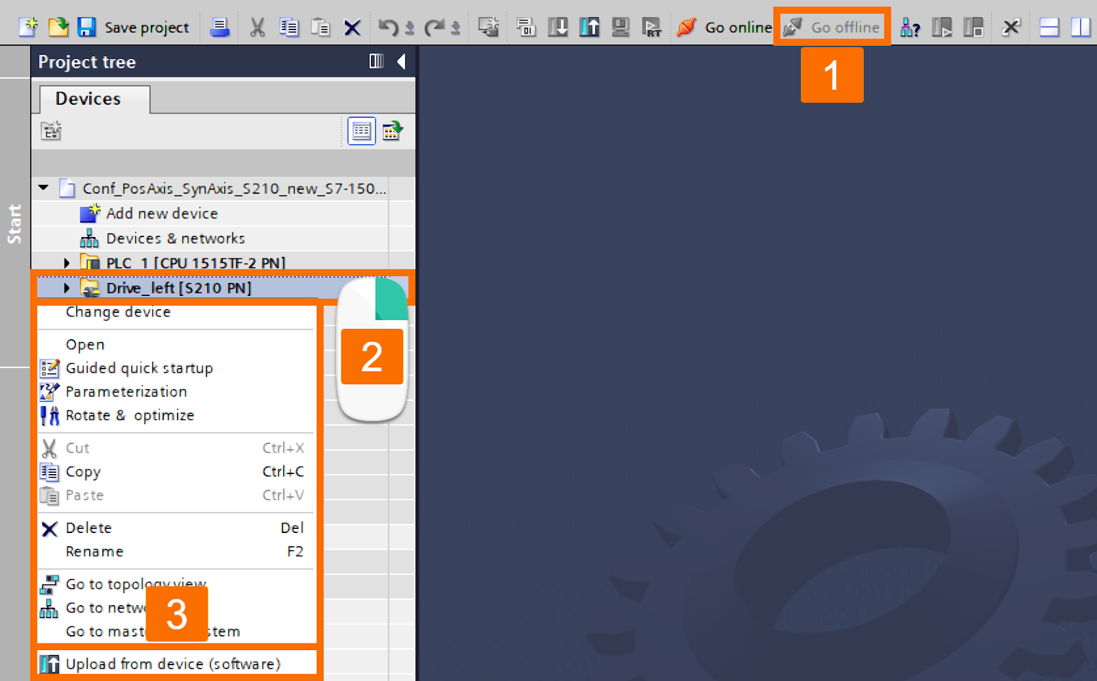
Use the 'Go offline' button to end the online connection. Then, right-click over the 'Drive_left' within the project tree and choose 'Upload from device (Software).'
Execute the "One Button Tuning" procedure for the 'Drive_right' as well.
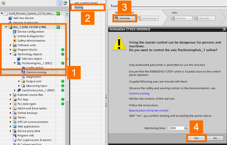
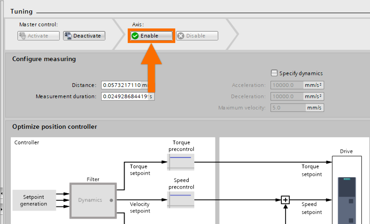
Initiate an online communication with the S7-1500 controller. To access 'Commissioning,' expand 'PLC_1' in the project tree and navigate to the 'Technology objects' folder. Double-click it. Navigate through the workspace menu and select 'Tuning.' Locate the 'Activate' button, click it, and then acknowledge the safety check by selecting 'Yes.'
Press the 'Enable' button.
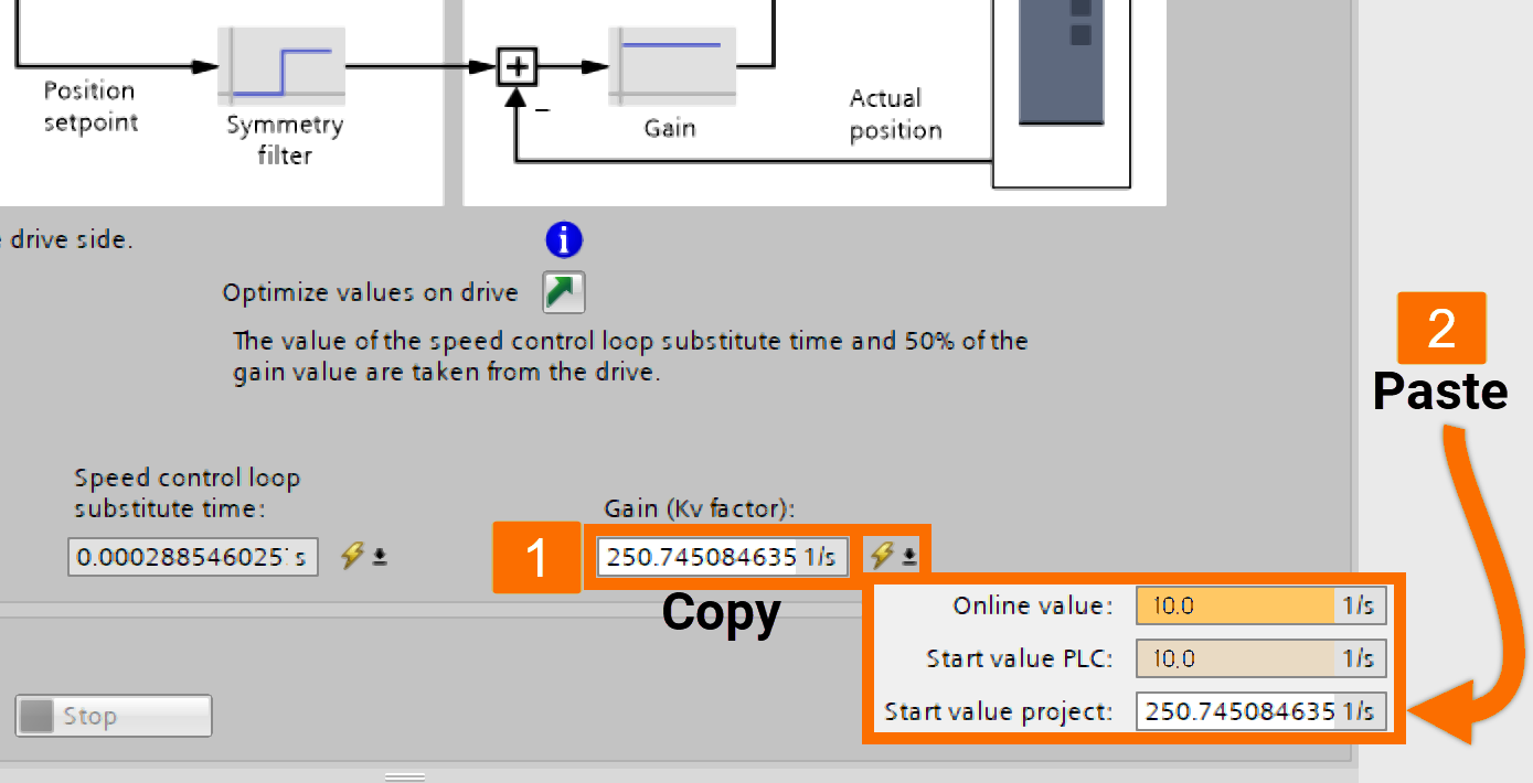
Select 'Take values from drive' to import the drive's values. Find the value for 'Speed control loop substitute time.' After copying it, left-click the icon to its right and transfer the value to the field of 'Start value project' by pasting.
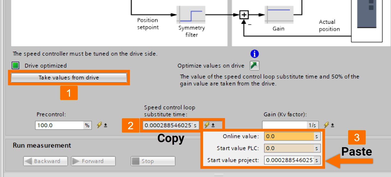
Execute the same procedure for the Kv factor as well. Then, ensure to save the project and transfer it to the controller.
Online Testing – Moving Along the Leading Axis
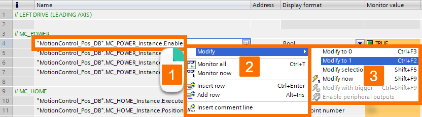
Establish the online connection, go to the watch table, and tap 'Monitor all.'
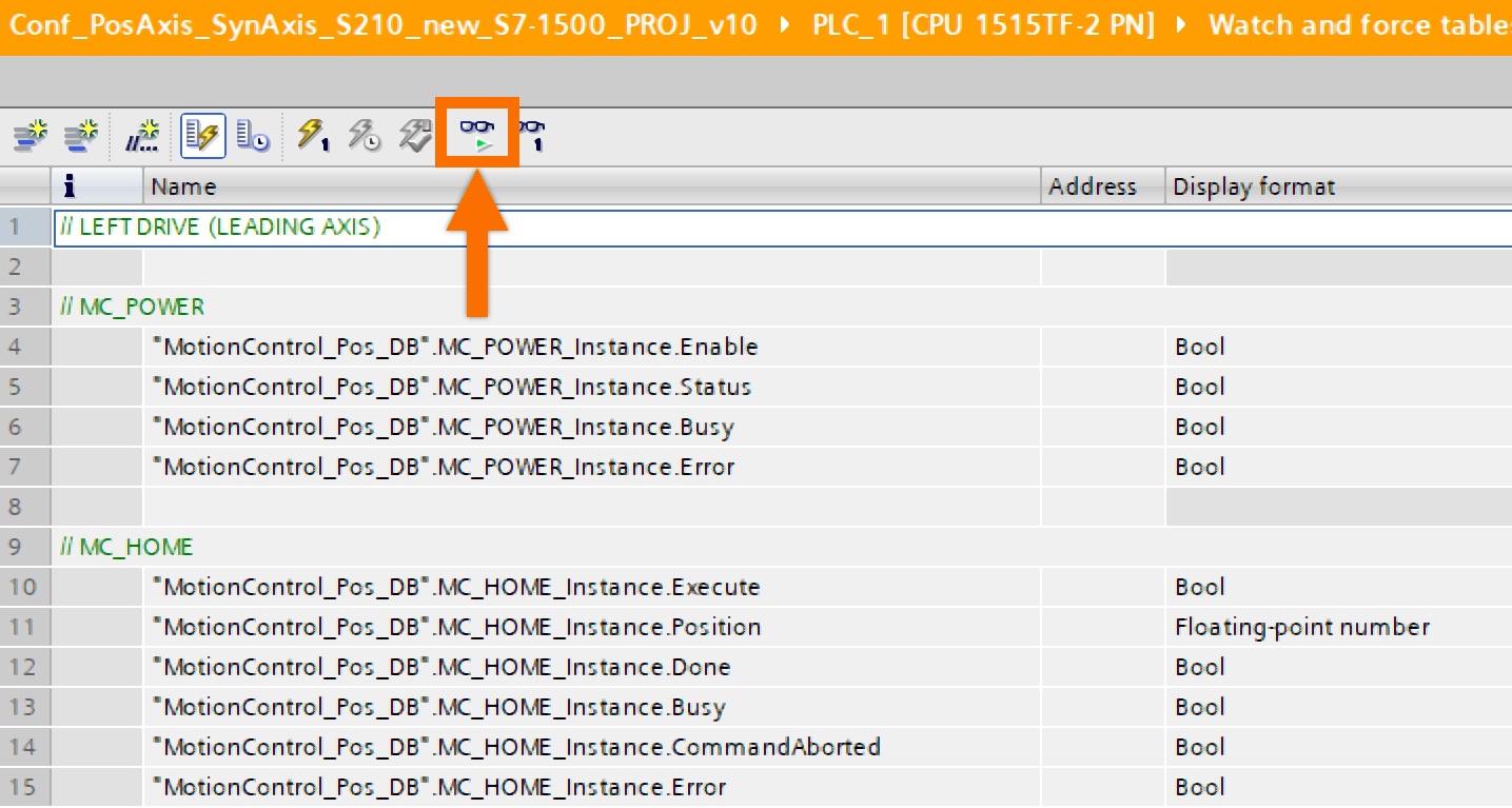
Right-click on the 'Enable' value under 'MC_POWER' and choose 'Modify to 1' from the 'Modify' menu to initiate the 'Drive_left.'
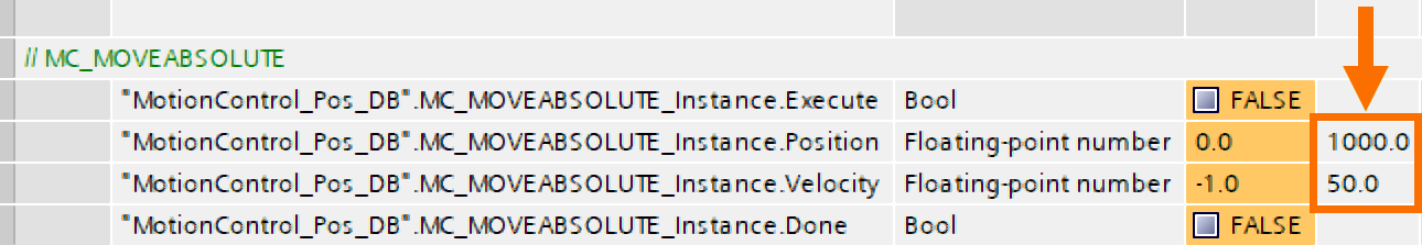
In the 'Modify value' column, input your preferred values for 'Distance' and 'Velocity' under the 'MC_MOVERELATIVE' section.
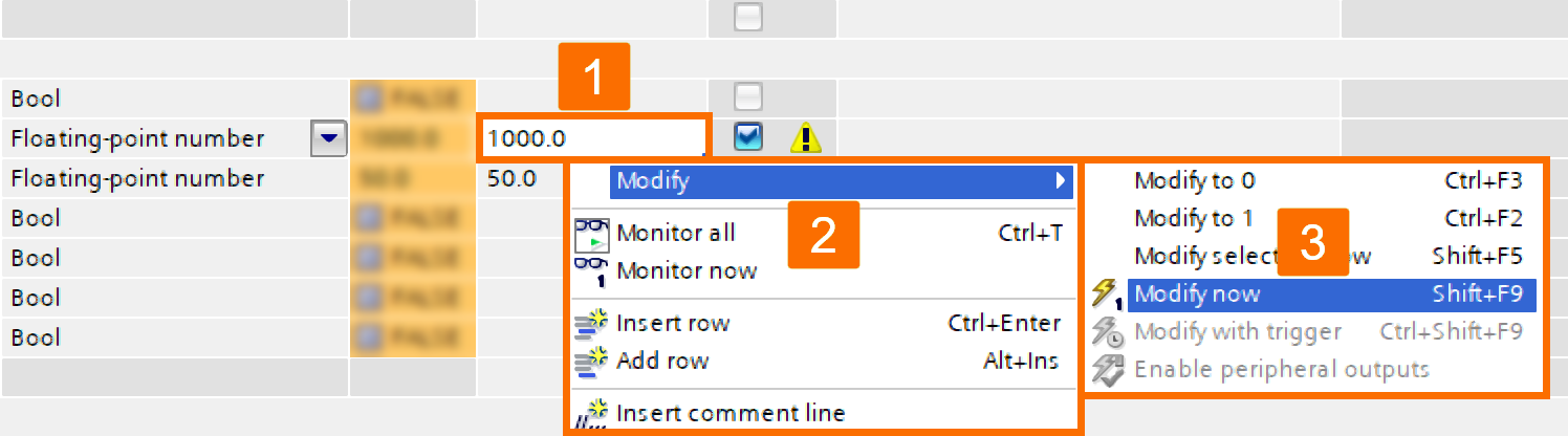
Right-click any value that has been modified, and then, from the 'Modify' submenu, select the 'Modify now' option.
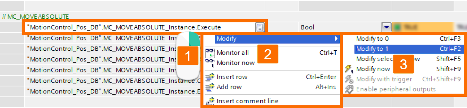
To run 'Drive_left,' right-click the 'Execute' value within the 'MC_MOVERELATIVE' section and pick 'Modify to 1' from the 'Modify' submenu.
To halt the 'Drive_left,' right-click the 'Execute' value within the 'MC_MOVERELATIVE' section and pick 'Modify to 0' from the 'Modify' submenu. Right-click on the 'Enable' value under 'MC_POWER' and choose 'Modify to 0' from the 'Modify' menu to deactivate the 'Drive_left.'
Online Testing – Moving Along the Leading and Following Axes
Now, within the 'MC_Power' section, power up 'Drive_left' and 'Drive_right' by toggling the value of 'Enable' to true.

Homing the 'Drive_left' involves assigning the value of 'Position' as zero within 'MC_HOME.'
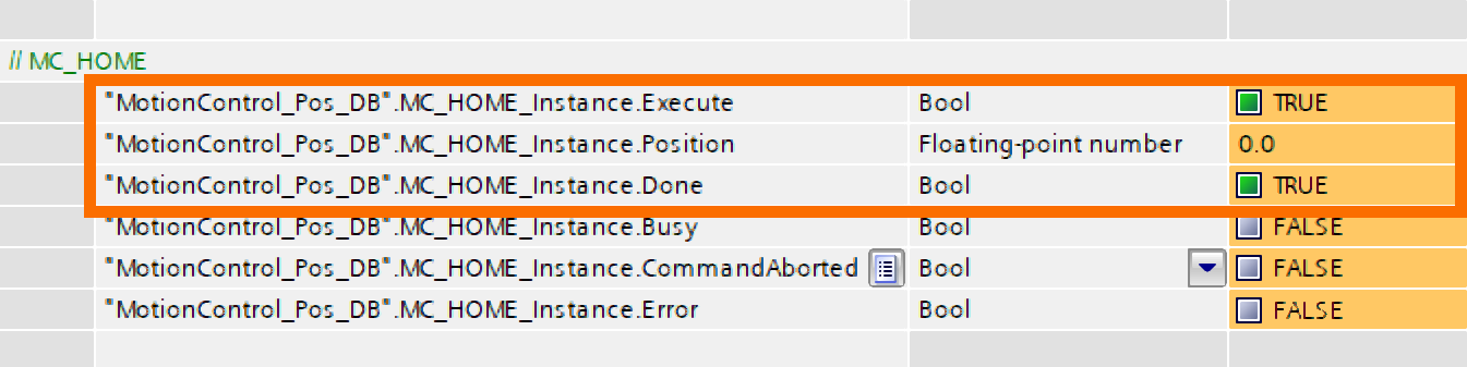
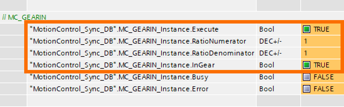
Initiate synchronous functionality for 'Drive_right' by toggling the value of 'Execute' to true within the 'MC_GEARIN' section.
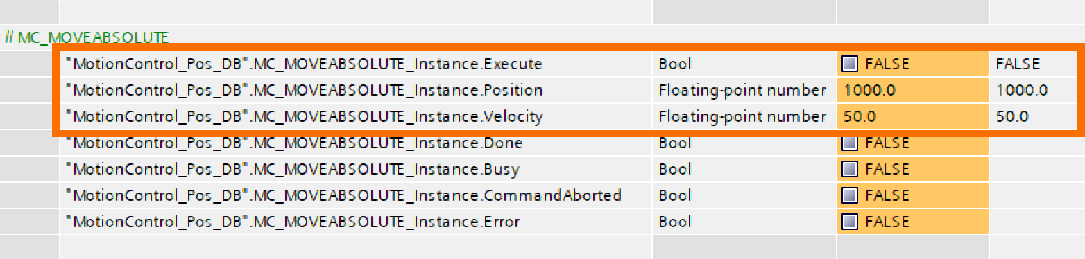
Input your target values for 'Distance' and 'Velocity' within the 'MC_MOVEABSOLUTE' section, then execute the 'Modify now' function.
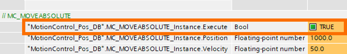
Kick off the drives by configuring the 'Execute' parameter within 'MC_MOVEABSOLUTE' to true.
Halt the drives by configuring the 'Execute' parameter within 'MC_MOVEABSOLUTE' to false. Deactivate 'Drive_left' and 'Drive_right' by toggling the value of 'Enable' to false within the 'MC_POWER' section.
Online Testing – Jogging for Accurate Movement
Once again, within the 'MC_Power' section, power up both drives by toggling the value of 'Enable' to true.
Initiate synchronous functionality for 'Drive_right' by toggling the value of 'Execute' to true within the 'MC_GEARIN' section.
Input your target value for 'Velocity' within the 'MC_MOVEJOG' section, then execute the 'Modify now' function.
Launch the drives by configuring the 'JogBackward' or 'JogForward' values to true within the 'MC_MOVEJOG' section.
Halt the drives by configuring the 'JogBackward' or 'JogForward' values to false within the 'MC_MOVEJOG' section. Deactivate both drives by toggling the value of 'Enable' to false within the 'MC_POWER' section.
Conclusion
In conclusion, this tutorial guided you through seamlessly integrating Siemens Motion Control Systems into the TIA Portal environment using Technology Objects. You learned to configure PLC and drive hardware, establish connection settings, and configure Technology Objects for positioning and synchronous axes. Additionally, you gained practical skills in developing TIA Portal logic for effective motion control. Through phases like initialization, fine-tuning, and online testing, you acquired the ability to commission and test the integrated system, enabling precise and efficient automation in industrial applications.