Accessing TIA Portal’s PLC tags using Node-RED

Introduction
The Industrial Internet of Things (IIoT) has revolutionized how industrial systems and devices are connected and controlled. In the Siemens industrial environment, where efficiency and seamless integration are paramount, Node-RED has emerged as a powerful tool for IIoT applications. Node-RED provides a visual programming interface that simplifies the development of IIoT solutions by allowing engineers to connect and automate devices and services through a flow-based approach. By leveraging Node-RED's capabilities, engineers can easily interface with Siemens PLCs and access tags to collect real-time data, perform analytics, and enable automation in the industrial ecosystem.
Node-RED is a versatile and user-friendly programming tool that facilitates the creation of automation and IoT applications. It operates on a graphical interface where users connect different nodes to perform various operations. These nodes represent functionalities such as data acquisition, data processing, communication protocols, and control logic. Users can build complex workflows and automate processes without extensive coding by linking these nodes together. Node-RED supports many nodes and integrations, making it compatible with numerous devices, protocols, and services. In the context of accessing PLC tags in the TIA Portal, Node-RED offers specific nodes that utilize the S7 communication protocol, enabling seamless connectivity and communication with Siemens PLCs.
In this tutorial, you will learn how to access PLC tags in the TIA Portal using Node-RED. The tutorial covers the configuration and programming steps required to establish communication between Node-RED and the PLC using the S7 palette.
Prerequisites
To follow this tutorial, you will need an installation of Node-RED, TIA Portal, and PLCSim Advanced. We will be using the latest versions to date, but you can use any other version. No additional hardware or software is required.
TIA Portal side - Configuration and program
Let’s start by creating a TIA Portal project containing a CPU of your choice. Here we will use a 1511 CPU coupled with a 16*DI/16*DQ module. The IP address of the CPU is configured to 192.168.0.10. Later in the tutorial, we will use a PLCSim Advanced instance to simulate this station.

We will use a package with the S7 communication protocol on the Node-RED side. So we need to activate the “Permit access with PUT/GET communication from remote partner” option.

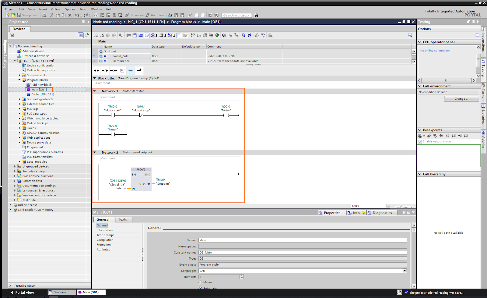
To test the acquisition of data by Node-RED, we will use the following small program which contains a motor start/stop section and a motor speed setpoint section.
In addition to the main program, we will use a global Data Block containing different types of elements (boolean, integer, real, and string) we will access directly from Node-RED.
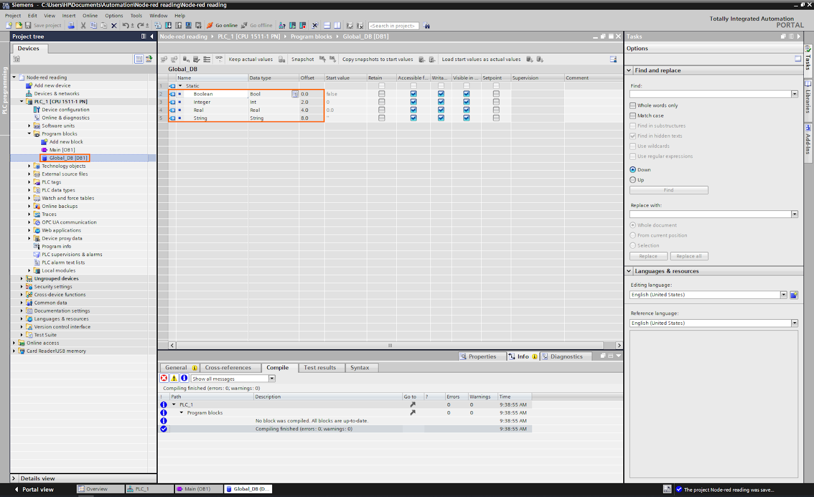
Also, we need to turn off the data block optimization for this DB to be able to access it from Node-RED using each element’s offset.

Node-RED side - Configuration
Now let’s head to the Node-RED side. Node-RED works with a graphical language where you link blocks called "nodes" to perform different operations. Here, we will use a library (or “Palette”) that handles S7 communications directly and connect them to other nodes to send or retrieve data.
Open Node-RED on your web browser (Using the “http://localhost:1880” address). You should see the Node-RED interface appear. The white space in the middle is the workspace where we put and link nodes. On the left is the node list, where you can find all available nodes in your software.

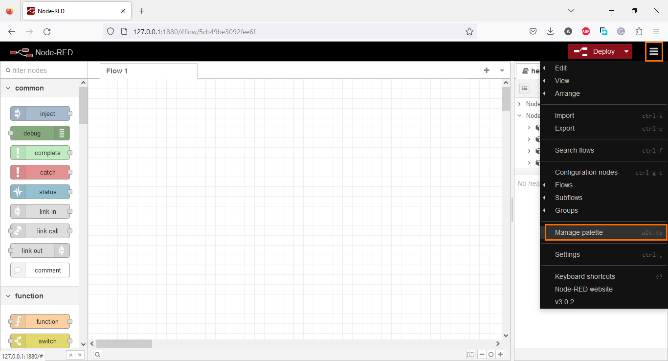
We need first to install the S7 palette. Open the options on the left and click on “Manage palette”.
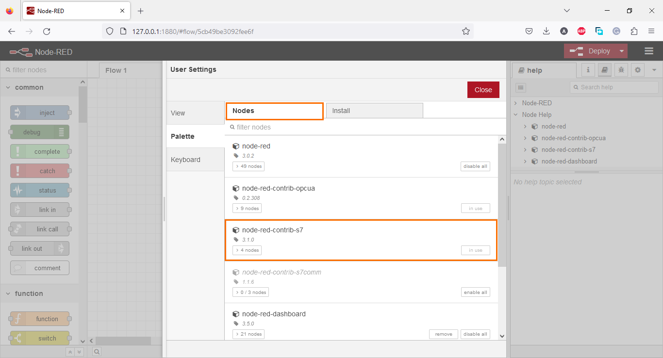
Palettes already installed in your Node-RED are displayed in the “Nodes” tab. For example, the palette we are looking for is already installed on my server.
To install a palette, open the “Install” tab and type the name of the palette you are looking for. In our case, type “contrib-s7”. It should appear in your list as shown below. Then, click on “Install”

Once the s7 palette is installed, scroll down the list of your nodes until you find the “plc” section where you can find the s7 communication nodes.
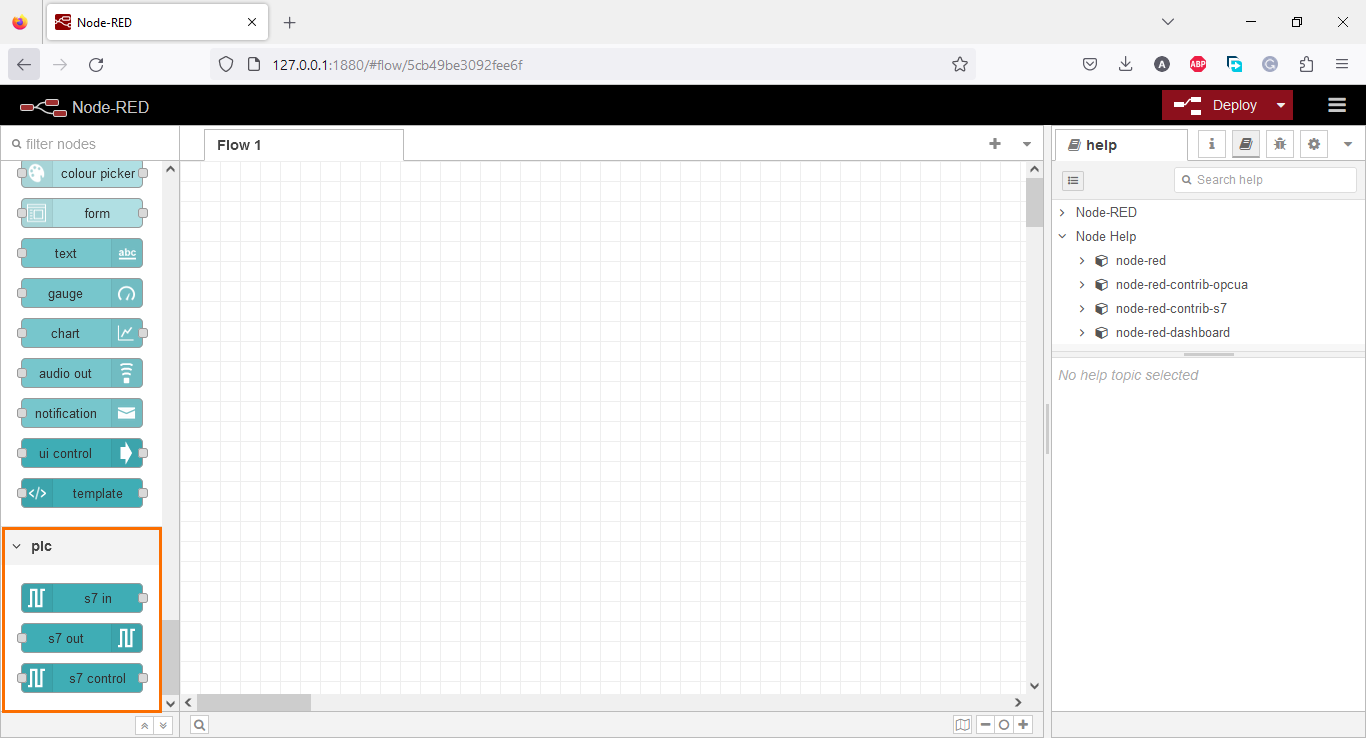
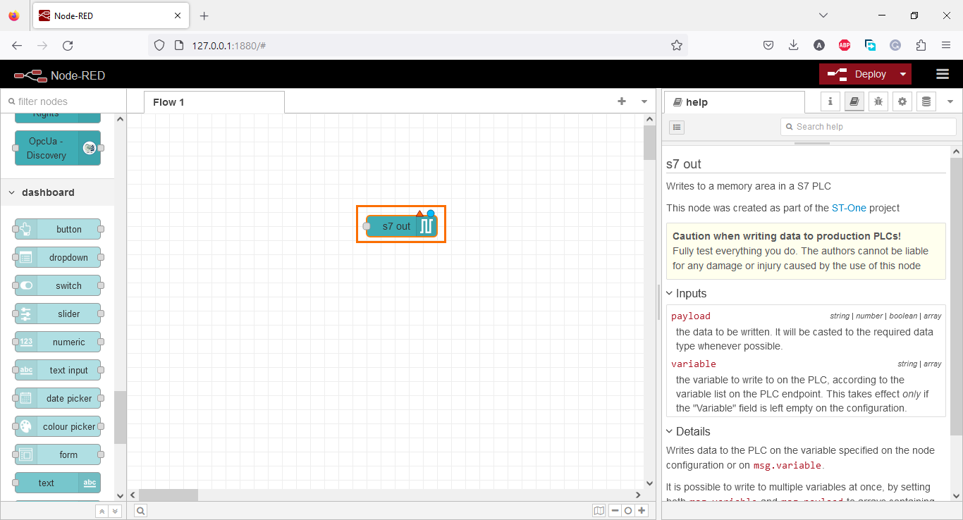
There are two primary nodes we will use; S7 in to read data from the PLC and S7 out to send data to the PLC. Grab one of each node and drop them in the workspace.

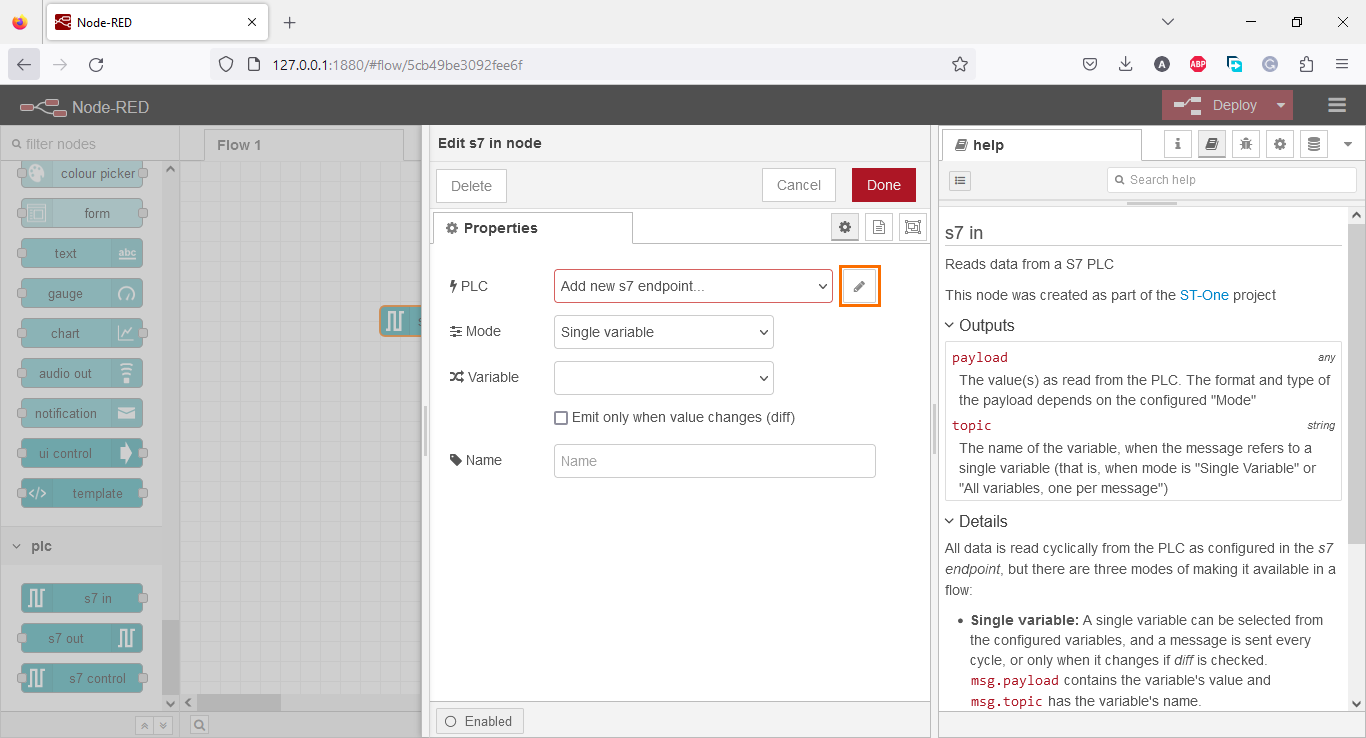
These nodes must be configured to access the PLC. We have to define an endpoint that will serve as an interface to access the station we configured previously. Double-click on any of these nodes. This will open the properties section of the node. In the PLC field, click the edit icon to create a new endpoint.
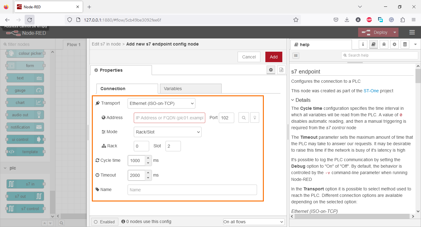
An endpoint is defined by the IP address, rack, and slot of the CPU we want to access. The port must be kept at 102 because the s7 communication protocol uses it.
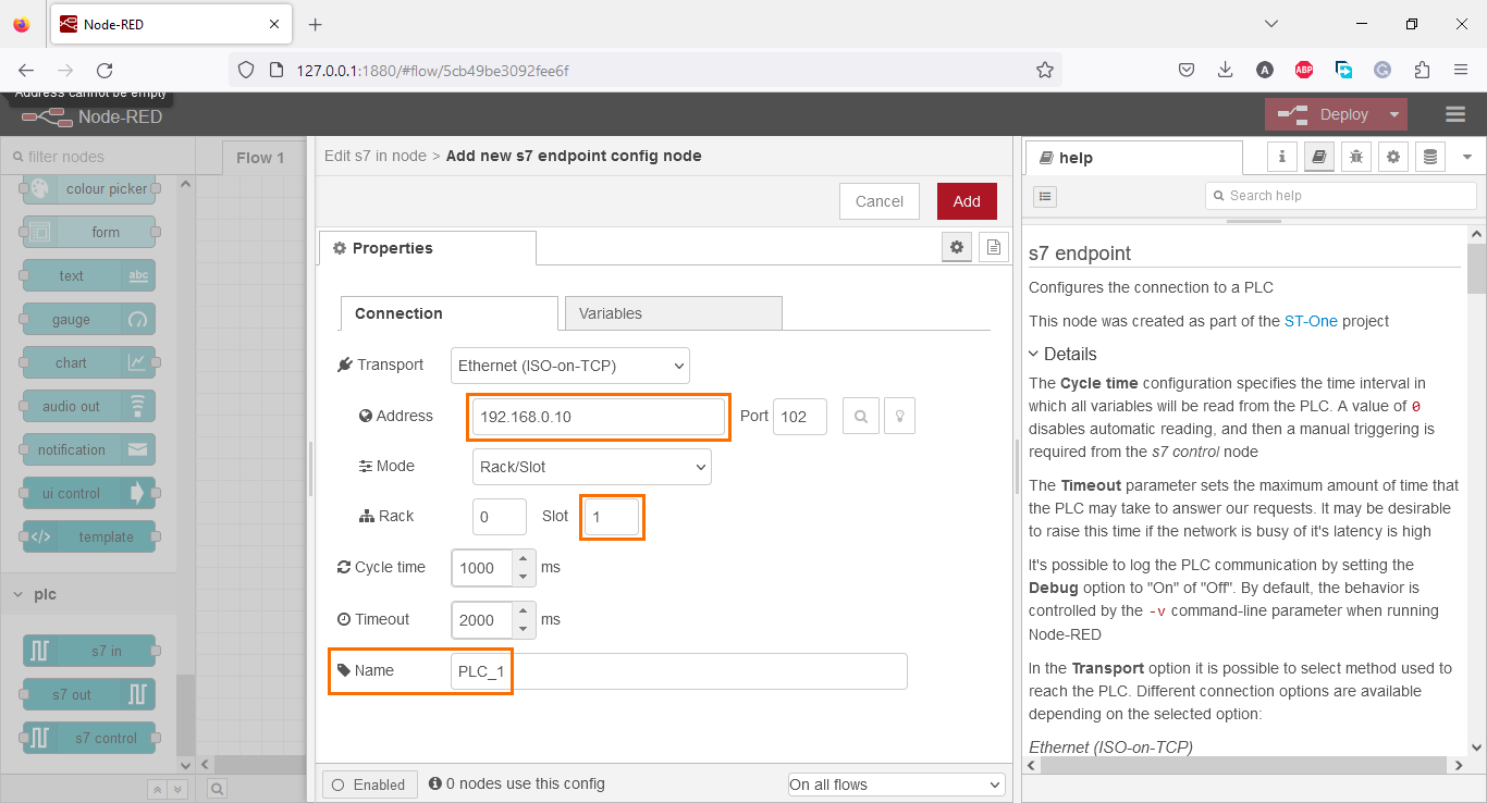
Add the IP address of the CPU we created previously (192.168.0.10), change the slot number to 1, and give a name to the endpoint (“PLC_1” here).
After configuring the connection settings, we must define all the variables we want to access in that endpoint. For this, open the “Variables” tab and add all the tags and DB elements we created in the PLC, as shown in the figures below.
![Figure 2.10 - Using Node-Red with Siemens TIA Portal PLC Programming | Endpoint variables [part 1 / 2]](https://cdn.prod.website-files.com/63dea6cb95e58cb38bb98cbd/64bdc98ded383c4f36d042e9_lv9qKZAG9T494LYl9SZSMKV4YfVaHcBfn6bhwWTECTBWIebnsmvp8i67eaFQtlaS_DLbwm1jrjMf7b4OLSPWbCC_MzV7URFzscSyFd1FjjPd_4NhBwonSCkx67b57rwK8eSZOqz7uH0jJczlBNlp9ek.png)
![Figure 2.11 - Using Node-Red with Siemens TIA Portal PLC Programming | Endpoint variables [part 2 / 2]](https://cdn.prod.website-files.com/63dea6cb95e58cb38bb98cbd/64bdc98d79e0f267cc352c41_14KTm6JnqtLanSQLTVUhEDA_TmWRyi-_Kl2zWwzP1txjlc8nzBR-CWKAogum5j7BstXmJ7VBDUNGPuums4jMaTFmE4UtKK6nnin9GwyoSb88HhueSYsSrYgTINjJtoXK7dTGNacS6YtNcpilF0xZRhI.png)
More details about the s7 palette is available in its official documentation.
We have now created and configured an endpoint to connect to our PLC. This endpoint will be used in all nodes that we will use later in this tutorial.
Node-RED side - Programming
We are done configuring everything. We can now move to the programming of the Node-RED side.
Let’s start by writing the motor control section of the program. Delete all previously added nodes and drop an S7 node in the workspace.
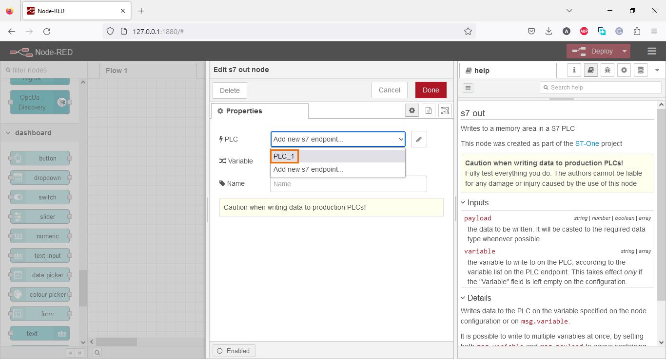
Double-click on the node to access its properties. Open the “PLC” section and select “PLC_1” (The endpoint we created previously).
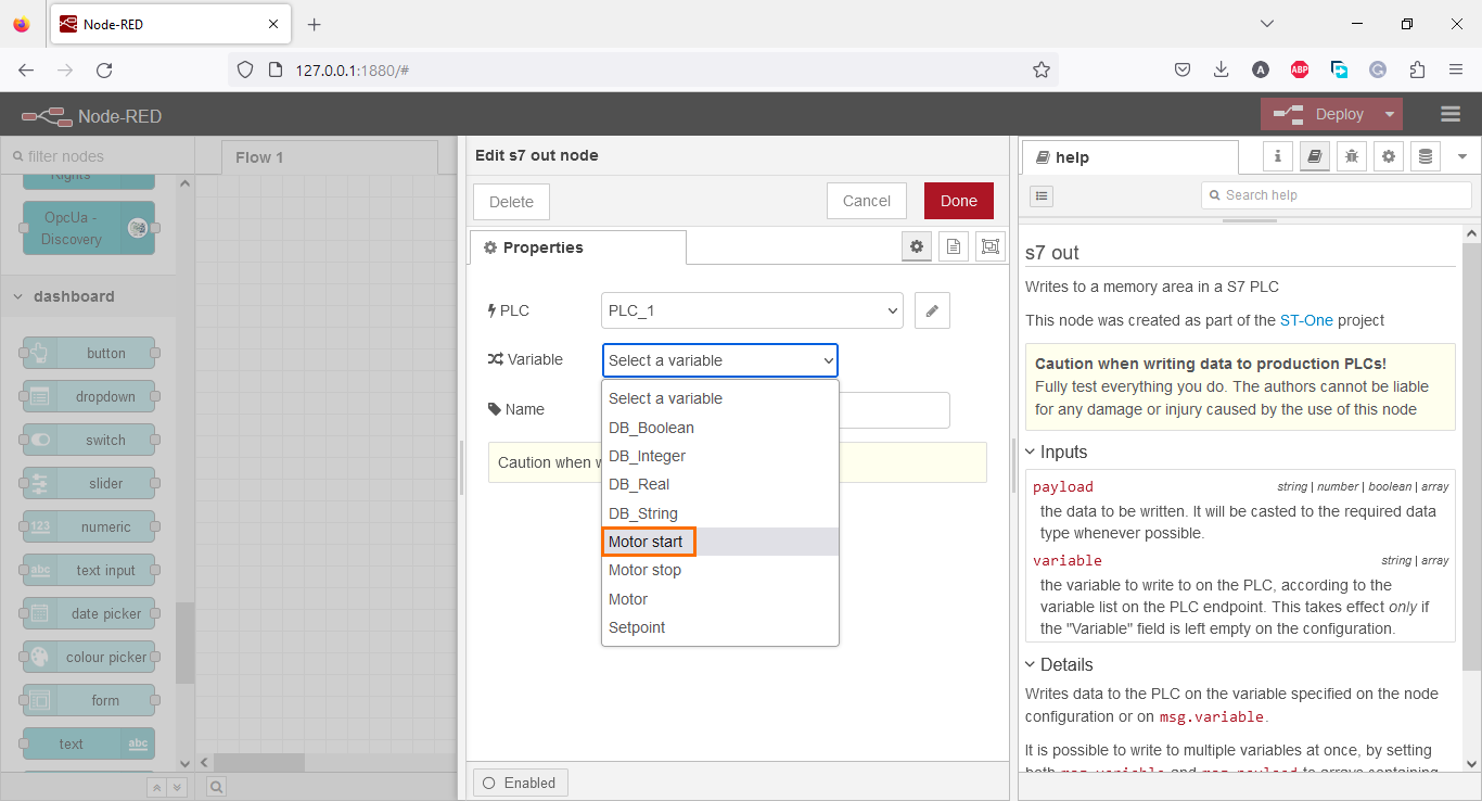
Then, in the “Variable” section, we have to select the variable we want to access (Among the endpoint’s variables). Let’s start with the “Motor start” boolean.
Don’t forget to name the node to avoid any confusion later.

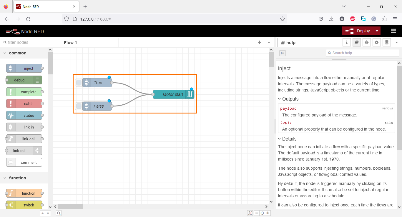
Now this S7 node is linked to the “Motor start” tag in the PLC. To change its value, we have to send either a 1 or a 0 to the node so it can deliver it to the PLC. To do this, we need two “inject” nodes. One for the 1 (True) state and the other for the 0 (False) state. Both will be wired to the “Motor start” node.

Double-click on the first “inject” node and change its payload type to “boolean”.
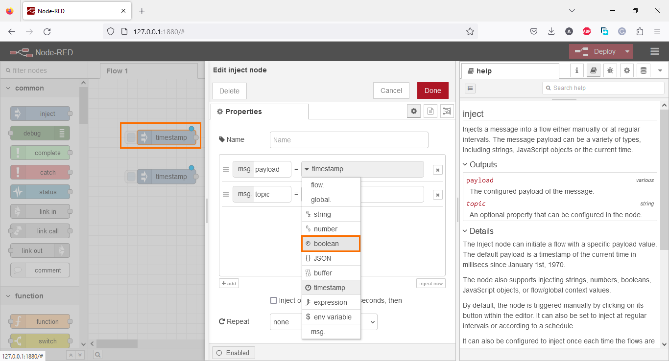
Then select the state as “true.”

Repeat this operation with the second “inject” node but select the “false” state instead. Don’t forget to name both “inject” nodes.

Once done with the node configuration, click on the right end on each “inject” node and wire them to the “Motor start” node. During execution, when you click on an “inject” node, it will its data to the connected node. We will be able to control the “Motor start” boolean on the PLC by clicking on these nodes later.
We can repeat this whole process of creating s7 out and inject nodes to apply it to the “Motor stop” this time. Select all the nodes we create, copy them, and paste them. Then, edit the s7 out node properties and select “Motor stop” as the variable.

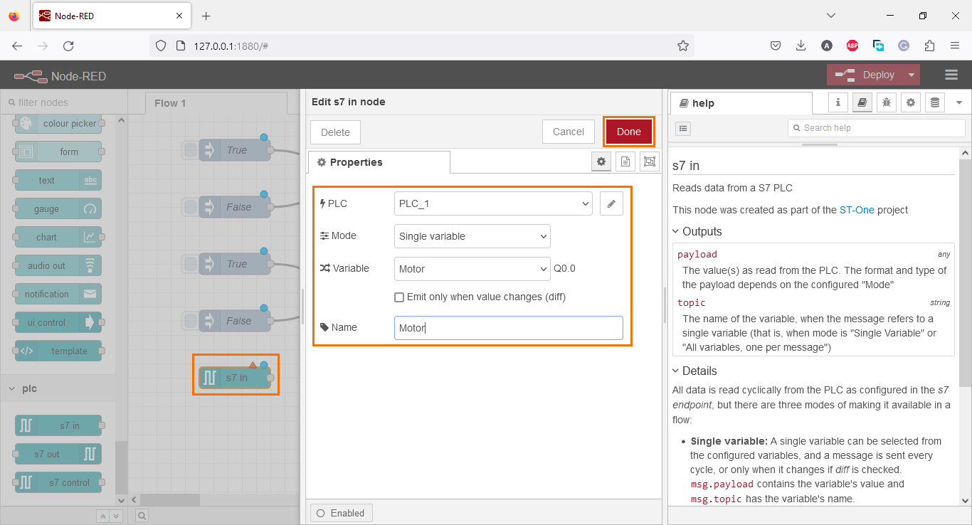
Now let’s head to the read section. Drop a “s7 in” node in the workspace. This node reads a tag from the PLC to display it or use it in another way.

Double-click on it. It will open its properties. Select “PLC_1” as PLC and “Motor” (Boolean) as the variable.
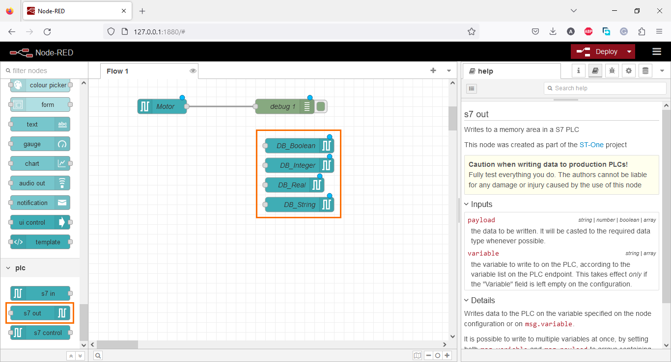
Now that we can read a tag, we must do something with it. We can, for example, display it in the debugging window of Node-RED. To do this, we have to use a “debug” node. Drag and drop a “debug” node in the workspace and link it to the “Motor” node. This will display the state of the motor in the debug window.

We are done with motor control, we can proceed to the DB section. Create four s7 out nodes. Connect each node to “PLC_1” and select the DB elements as variables as shown in the figure below.
The first node, “DB_Boolean”, is a boolean, we can copy the true/false inject nodes we created previously.
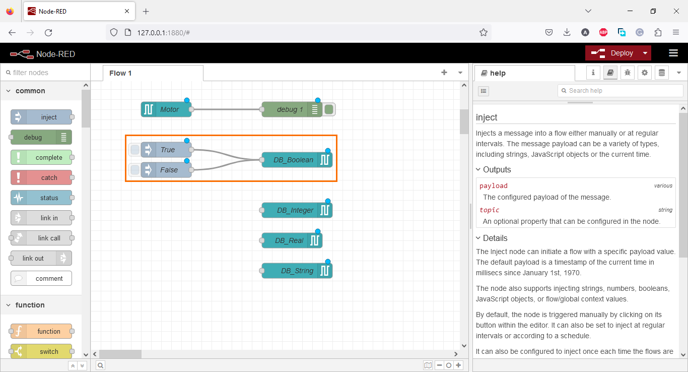
For the second node “DB_Integer”, we will also add an ”inject” node. Double-click on it and select “number” as the payload type.
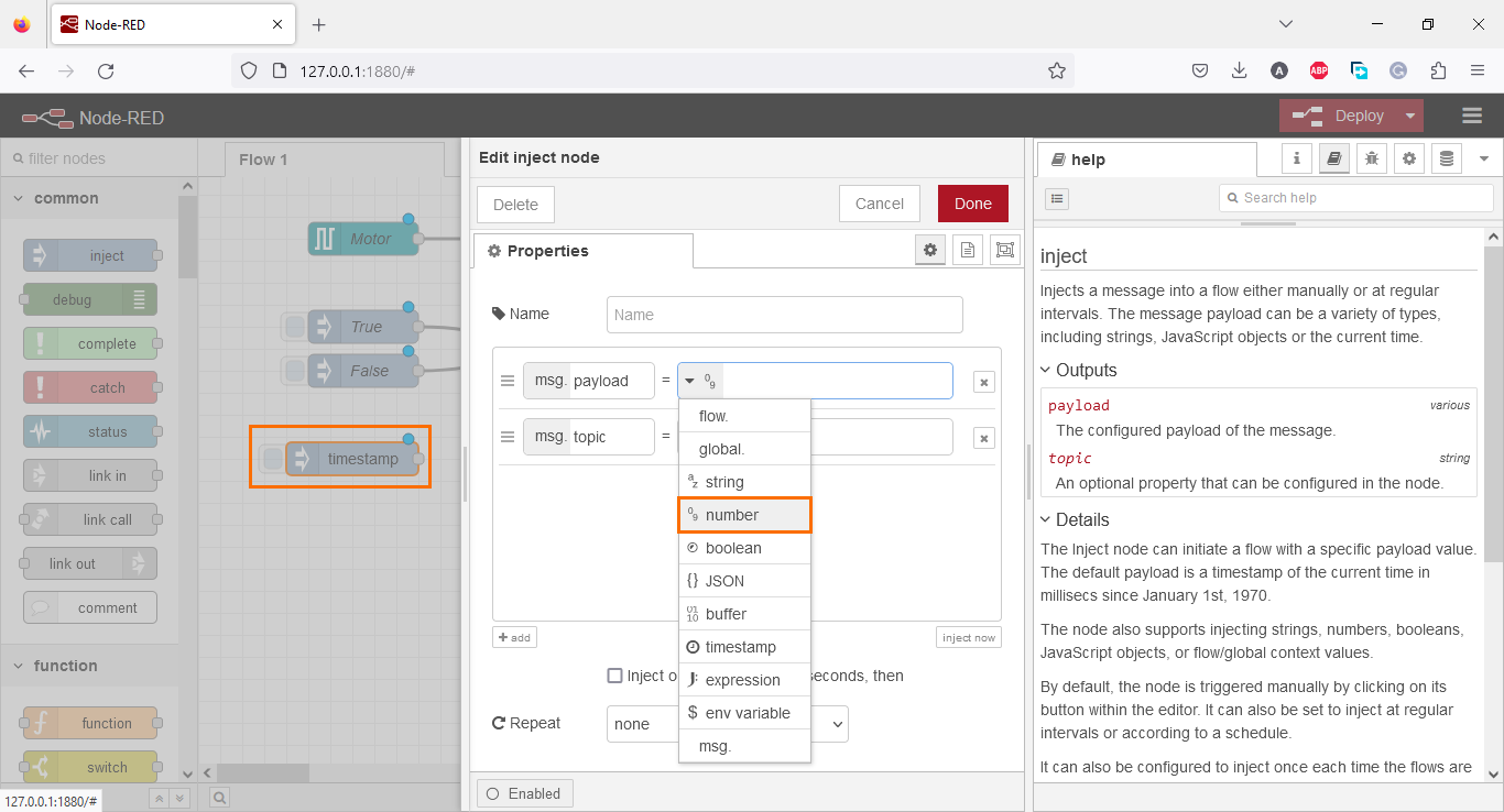
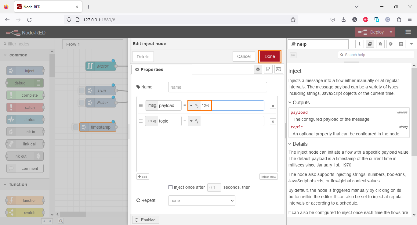
Then, add an integer value to the payload (136 for example).
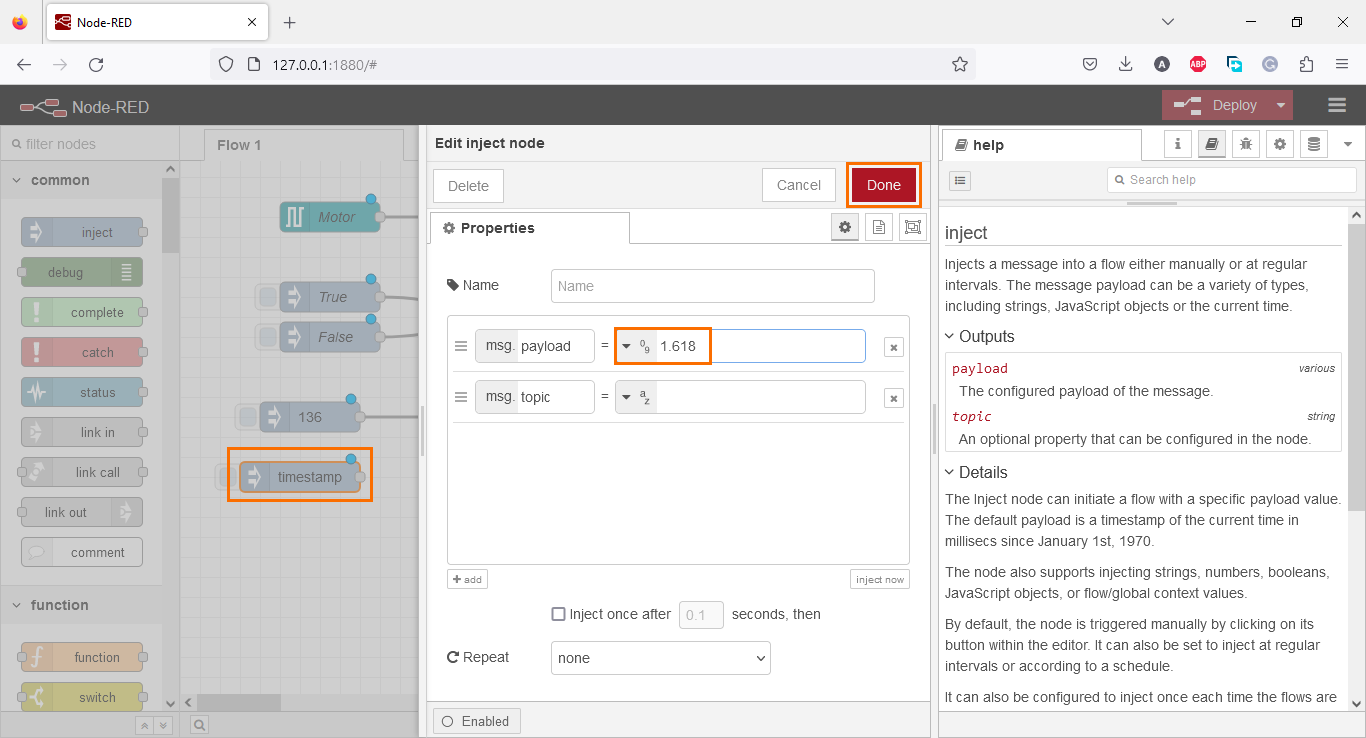
For the third node, “DB_Real,” repeat the same step as for the integer but here, type a real value (1.618, for example).
For the fourth node, “DB_String,” repeat the same procedure again but select “String” as the payload type.
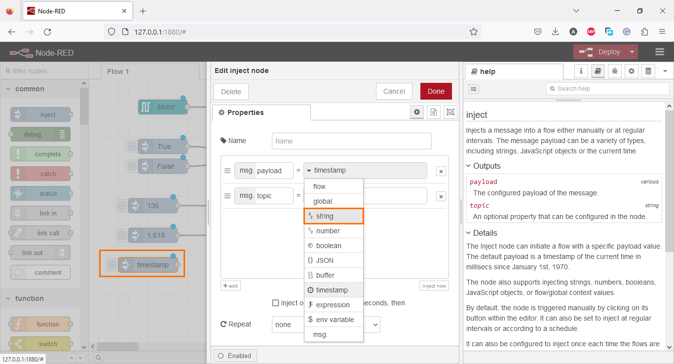
And type the character string of your choice (“Hello world!” for example).

Then, link each node to its associated s7 out node.
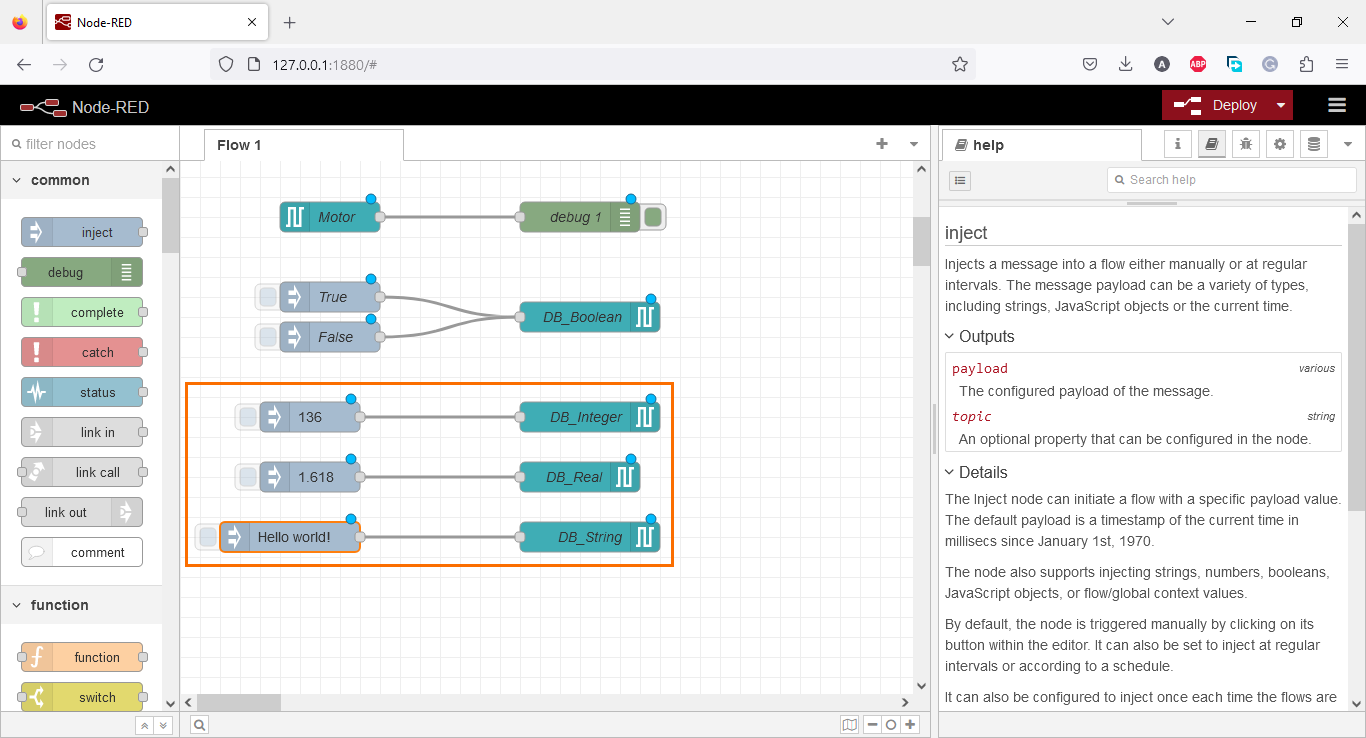
We added nodes to write over the DB elements; since the integer element is transferred to the setpoint tag, we can read the setpoint node to display the setpoint value. Create an s7 in node and wire it to a debug node.

The Node-RED program is done. It should look like the figure below. To execute it, click on “Deploy.”

Node-RED and TIA Portal - Execution
For this section, we will test both configurations and programs on Node-RED and TIA Portal. The expected behavior is that upon clicking on inject nodes, it will send their value to their associated s7 out nodes; Values are read from s7 in nodes and displayed in the debugging window.
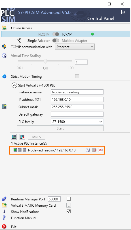
To simulate the PLC side, we will use a PLCSim Advanced instance configured to match the PLC_1 configuration as shown below and load the TIA Portal program into it.
The Node-RED program is deployed, and the PLC program is being executed, so the communication and data exchange must be established. Try to inject values to the PLC, as shown in the following figure.
On the motor control side, upon clicking on the inject nodes, the value of the PLC tags is correctly updated. The state of the motor is continuously displayed in the debugging window. everything works fine.
Now to the DB section.
Once again, clicking on inject instructions does update their values on the PLC side, and the value of the setpoint is correctly displayed in the debugging window and it follows the value of the integer value.
Conclusion
In this tutorial, you learned how to access PLC tags in the TIA Portal using Node-RED. We started by creating a TIA Portal project and configuring a CPU. Then, we installed the S7 palette in Node-RED and configured the S7 nodes to establish communication with the PLC. We created nodes to control the motor start/stop section and motor speed setpoint section and access and manipulate data in a global Data Block. Finally, we executed the Node-RED program and tested the communication and data exchange between Node-RED and the TIA Portal.
The seamless integration of Node-RED with the TIA Portal offers engineers a straightforward and efficient way to connect industrial systems. This integration is remarkably user-friendly, thanks to the S7 palette and its dedicated nodes for S7 communication. Engineers can easily design complex automation workflows without extensive coding using Node-RED's visual programming capabilities. The intuitive graphical interface empowers engineers to connect nodes, control PLC tags, acquire and manipulate data, and interface with other devices and services. With a vibrant community and a vast library of nodes, engineers can quickly access a wide range of functionalities, expanding the possibilities for industrial applications.
