An Introduction to Siemens SIMATIC Manager (STEP 7)

Introduction
Before the advent of TIA Portal, Siemens' SIMATIC Manager played a pivotal role in programming S7-300 and S7-400 PLCs, particularly for older CPU models still active in industrial sites. While TIA Portal has become the go-to platform for newer projects, many sites still rely on SIMATIC Manager to maintain and program their legacy systems.
SIMATIC Manager (Also known as STEP 7) is a powerful software tool developed by Siemens for programming and configuring Siemens S7-300 and S7-400 PLCs. It is the primary platform for designing, configuring, and maintaining automation projects. SIMATIC Manager provides a comprehensive environment for creating PLC programs, configuring hardware components, managing network communication protocols like PROFIBUS, and organizing program blocks. It remains indispensable for older PLC models and offers a structured approach to industrial automation engineering.
In this tutorial, you will learn how to navigate SIMATIC Manager and perform essential tasks for PLC programming. We will start by guiding you through project creation and providing an overview of the main interface. Next, we will delve into hardware configuration, explaining how to add and configure PLC stations and modules. Then, we will cover network communication using PROFIBUS, detailing how to set up connections between the PLC and other devices. Finally, we will introduce you to program block management, highlighting the four main types of program blocks and showing you how to create them. Additionally, we will discuss downloading programs to the PLC and uploading them for further maintenance and troubleshooting.
Prerequisites
To follow this tutorial, you will need an installation of SIMATIC Manager (STEP 7). Here, we will be using the version 5.6. No additional hardware or software is required.
Project creation and main interface overview
Let’s start by looking at how to create projects in Simatic Manager. First, start the Simatic Manager software. To do this, open your Start menu, browse the “Siemens Automation” folder, and click “SIMATIC manager.”

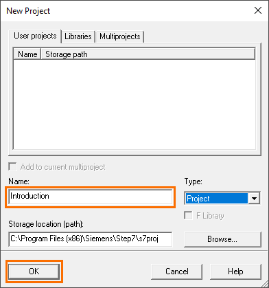
When the software opens, we must create a new project. Click on the “New project” button symbolized by a white page icon.

A small “New Project” window will appear where you can define the project’s name, the project’s type, and the storage location of the project.

Give the project a name, keep the type at “Project,” and click on “OK.”
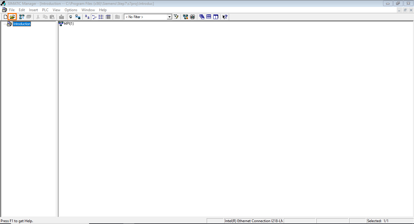
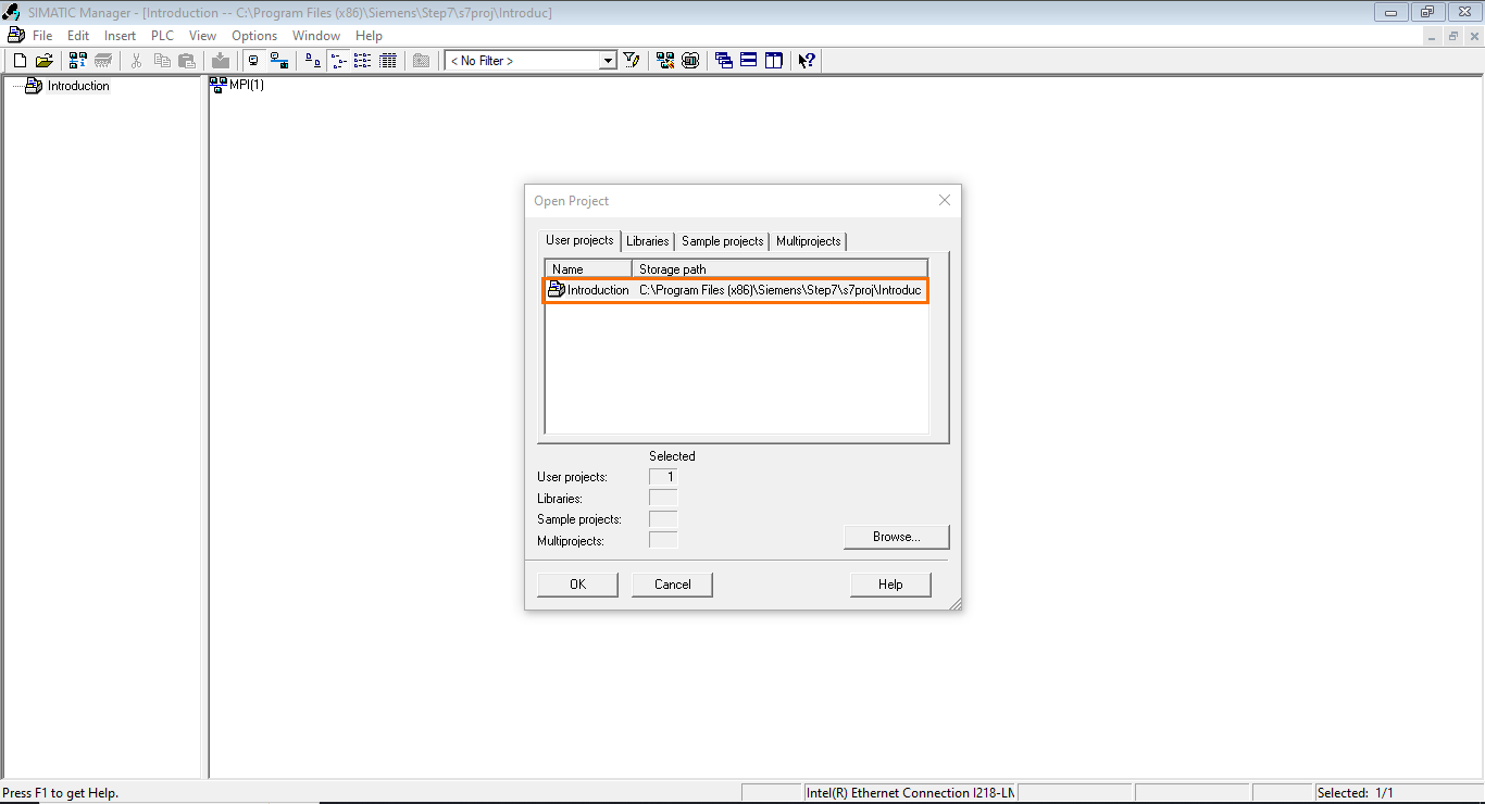
Wait for the project creation to finish. Once done, the project interface appears. Before covering the interface, let’s quickly look at how to open projects. To do this, click on the “Open Project” button symbolized with a yellow folder icon.
This will open a small “Open Project” window where you can find a list of all your projects. You should find the newly created project in this list.
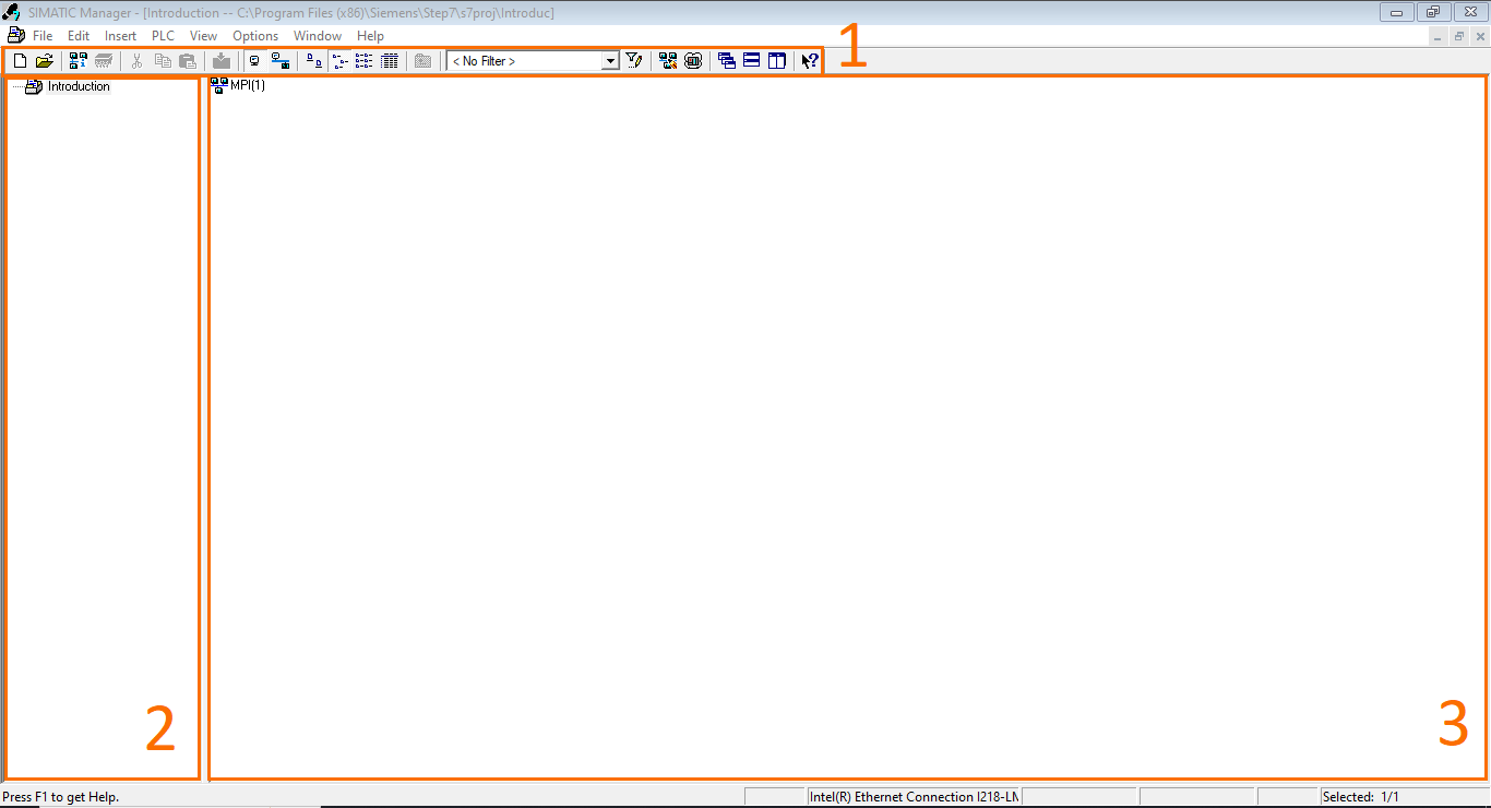
Now, you can close the “Open Project” window to come back to the main project interface, which is divided into three sections:
- Toolbox: Here, you can find various tools such as creating/opening a project, loading the project in a PLC, opening the network management, enabling the simulator, viewing options….etc
- Project tree: Here, you can find an exploded view of each component, offering quick access to any part of the project.
- Workspace: Here, you can find a more detailed view of the selected section of the project where you can find all the components included inside and interact with them.
Hardware configuration
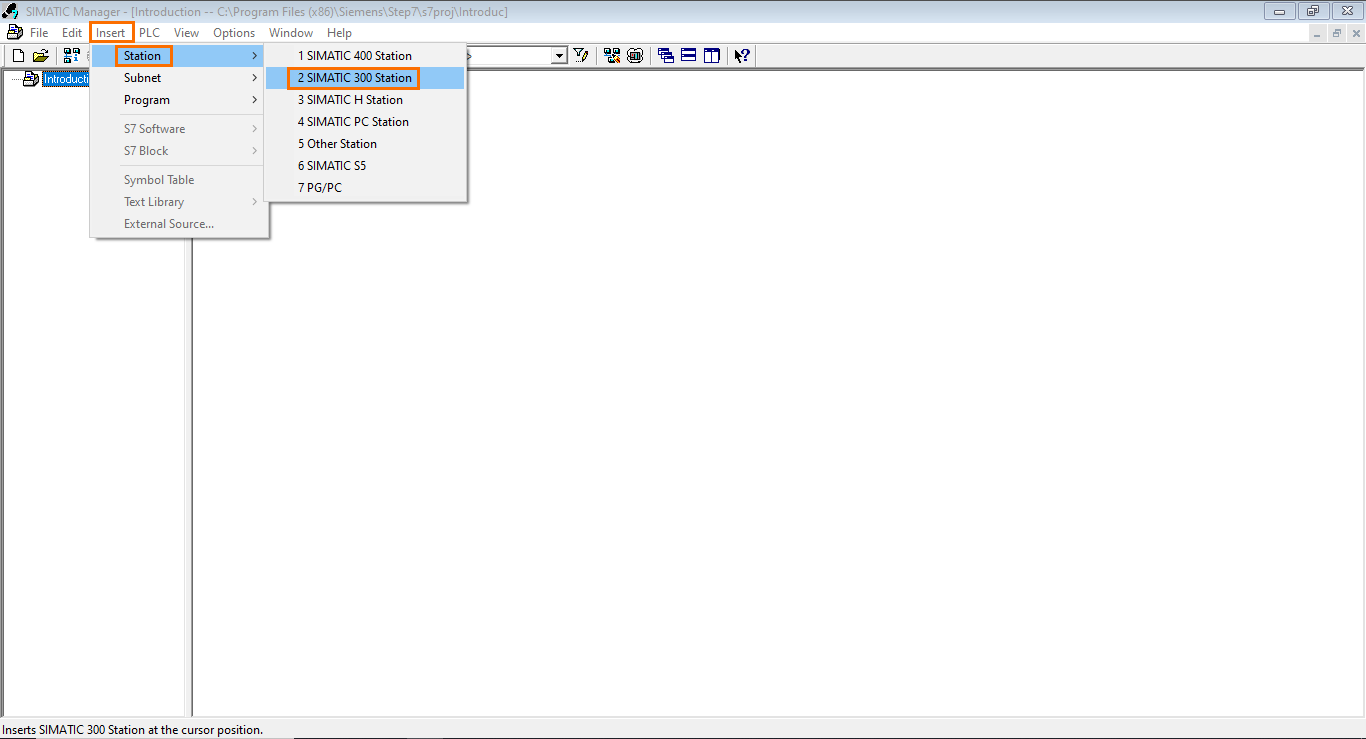
For now, the project we created is empty. Beforehand, we need to create a PLC station in the project. We will add an S7-300 PLC station to the project. To do this, open the “Insert” menu, select “Station,” and click on “SIMATIC 300 Station.”
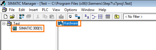
This will add a S7-300 station to your project. However, this station still needs to be configured. Select The SIMATIIC 300 station in your project tree and open the hardware section of the station to access the hardware configuration.
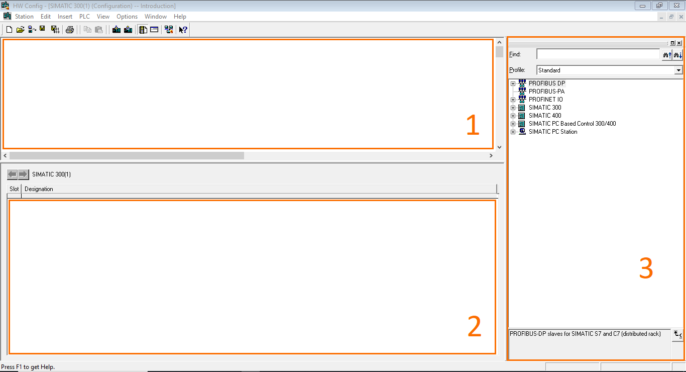
The hardware configuration opens in a new window. Here, you can configure the actual hardware used in your station using a catalog that contains all the various Siemens PLC components (CPUs, modules… etc.) for the 300s and 400s series. The components are added to replicate their physical layout (Modules positions in the rack).
The hardware configuration interface splits into three parts:
- Workspace: In this section, you can define a rack and add modules to it.
- Detail view: Here, you can find a detailed view of all the components in the rack.
- Hardware catalog: Here, you can find a list of all the different CPUs, modules, and devices that you can add to your rack. Contains only devices compatible with the S7-300 and S7-400 series.
The first thing to do is to add a rack. Open the ”SIMATIC 300” folder in the catalog. Here, you will find all the components available for the S7-300 PLCs. After that, open the “RACK 300” folder, where you will find the Rail component.

Drag and drop the rail to the workspace. This will add a rack list where you can add the PLC modules from the catalog.

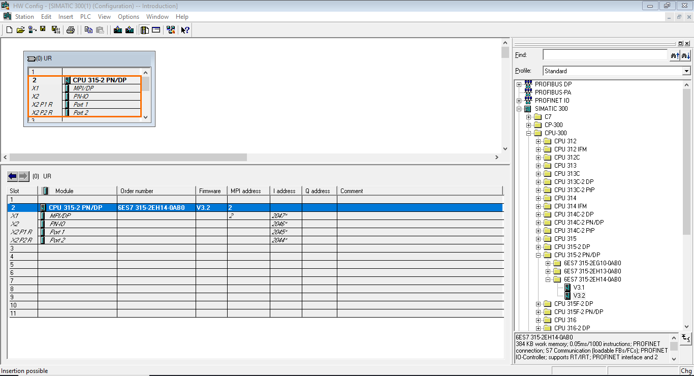
Now that we have added a rail, we can start adding modules. For this example, we will add an S7 315-2 PN/DP CPU, one of the most popular CPUs in the S7-300 series. To do this, open the CPU 300 folder. Here, you will find all the available S7 300 CPU models. Next, open the “CPU 315-2 PN/DP” folder. Three versions are available for this module, displayed with their order number. Select the last one and open it. You will find two available firmware versions for this CPU; select the highest and drag it to the rail. You will notice that only slot two highlights in green indicate that it’s the only slot. The first three rail slots are reserved as follows: 1- Power supply. 2- CPU. 3- Interface module (For multi-rack systems). Add the CPU to the second slot of the rail.

Adding the CPU will automatically open its properties. We don’t need to modify anything for now; you can close this window by clicking “OK.”
The added CPU will be displayed in slot 2 of the rail; you can also find more details about the CPU in the detail view.
After adding the CPU, we can add a signal module (Digital Input and Output). Instead of adding both a DI module and a DO module, we will add a DI/DO module. Open the “SM-300” folder, then the “DI/DO-300” folder, and select the first module available (SM 323 DI/16/DO16x24V/0.5A). Then, drag it to the rail. You will notice that all slots starting from slot four are authorized. Put it in slot 3.
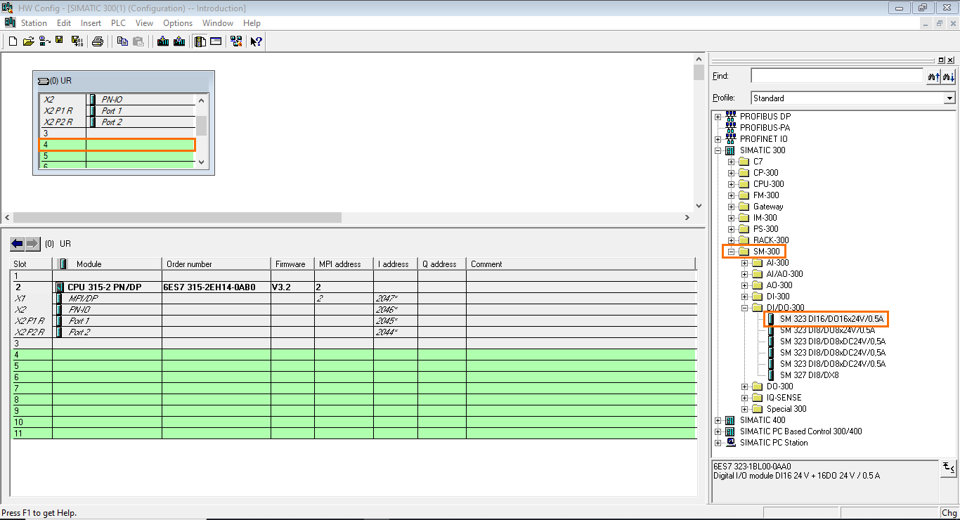
This will add a DI/DO module to the station. You can find more details about the module’s addressing in the details view.

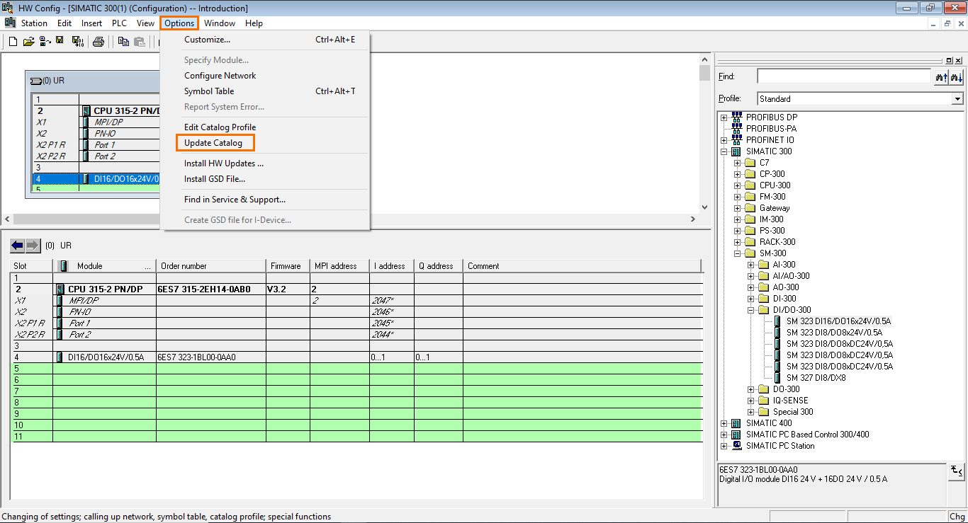
If you can’t find the module you’re looking for in the catalog, you can update the catalog from the internet to add all the missing components to your software. To do this, open the “Options” menu and click “Update Catalog.”
Network communication (PROFIBUS)
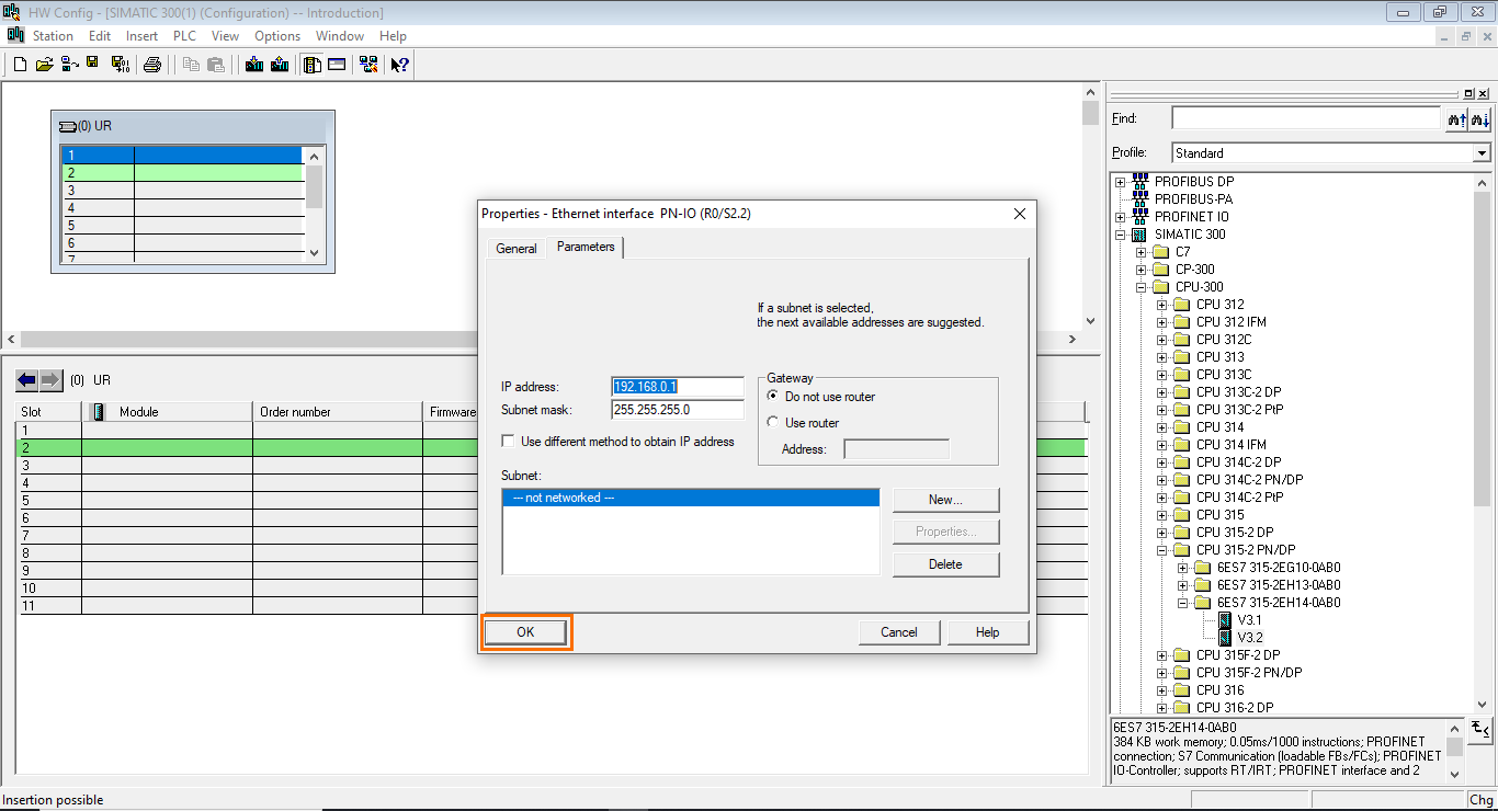
In cases where your CPU is connected to other devices through a fieldbus, such as PROFIBUS and PROFINET, we need to configure the network. Let’s configure a slave device connected to the CPU through PROFIBUS. To do this, double-click on the “MPI/DP” interface of the CPU in the hardware configuration.
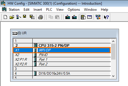
This will open the properties of the DP (Decentralized Periphery) interface of the CPU. Here, you can define the type of protocol used, the address, and the network properties of the interface.

First, open the types list and select “PROFIBUS.”

After this, open the network properties. Here, you can define the device’s address and the subnet. Keep the address at the default value and click on “New” in the subnet section.
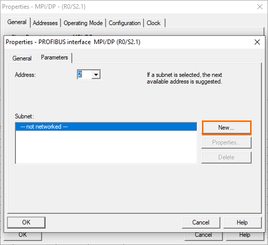
This will add a new subnet to your PROFIBUS network.
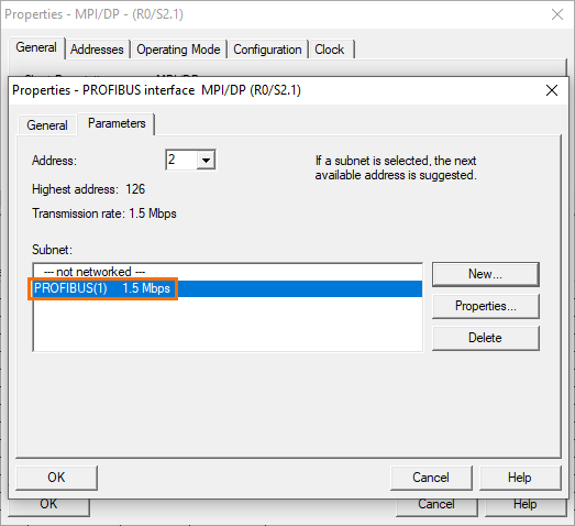
Now, go back to the hardware configuration. You will find a branch connected to the “MPI/DP” interface of the CPU. This branch is your PROFIBUS subnet.
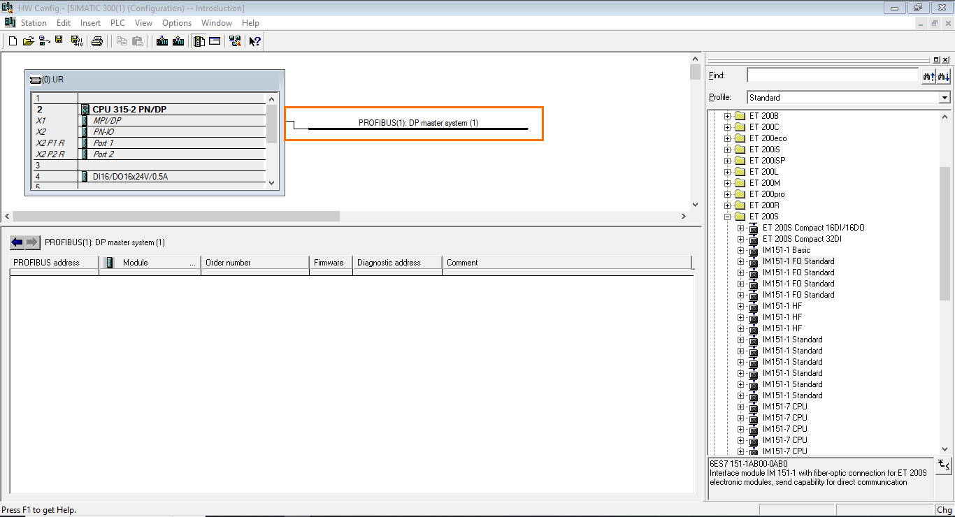
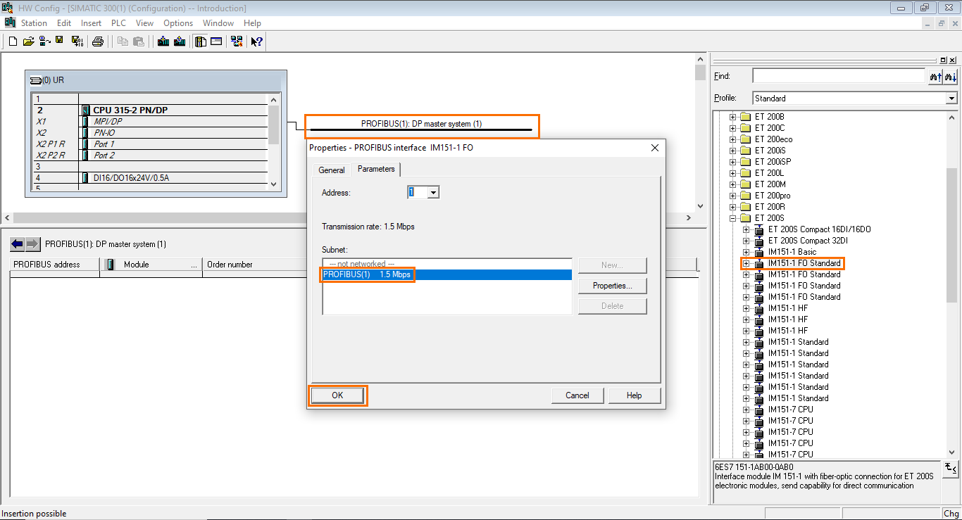
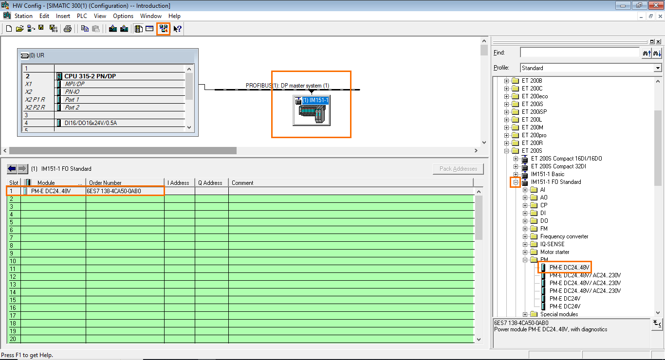
To this subnet, we can add slave devices such as ET 200 remote modules and other types of peripheral devices. To add a device to the network, drag the device to the network branch. This will open the device’s PROFIBUS properties. Select the subnet we created previously and click on “OK.”
Once the device is added, we can add modules to it to complete it. Adding a Power Module is mandatory. Add a “PM-E DC24..48V” module to the ET 200 device.
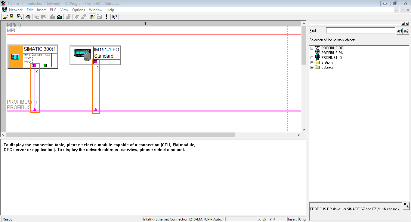
Once done, we can open the network manager to check the PROFIBUS configuration. Click on the “Open network manager” button.
Check that your devices (CPU and ET200) are connected to the PROFIBUS network in the network manager. If not, you can connect them using the graphic interface by selecting the device’s interface (pink square) and dragging it to the PROFIBUS network (Pink line).
Creating program blocks:
We are now done configuring the station. We can head to the program blocks management. As a reminder, PLC programs are split into different segments called “blocks.” You can program these blocks and link them together to build automation applications.
There are four types of program blocks:
- Organization blocks (OB): These blocks are the most essential blocks of a PLC program. They define the sequence and timing of program execution. OBs determine when and how often certain sections of the program are executed. They typically handle tasks like program startup, cyclic program execution, and fault handling.
- Functions (FC): These blocks are predefined or user-defined routines that perform specific tasks or calculations. Functions encapsulate and modularize certain operations, making the code readable and reusable. They can perform mathematical calculations, data manipulation, and other tasks.
- Data Blocks (DB): These blocks store and manage data such as variables, arrays, and structured data types. It allows you to organize and store data in a structured manner, making it easier to manage and access data throughout the program. They are commonly used to store process data, configuration settings, and input/output (I/O) data.
- Function Blocks (FB): These blocks are reusable program modules that encapsulate a specific control or automation function. They consist of a Function (FC) associated with a Data Block (DB). They can represent complex control algorithms like PID controllers, motor control, or communication protocols.
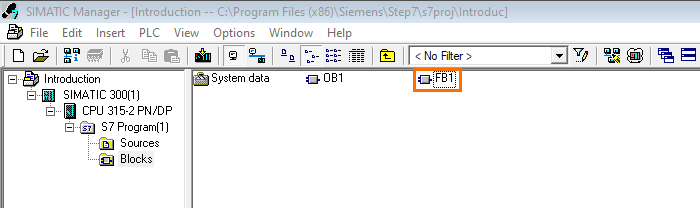
You can create, edit, and manage these blocks in the “Blocks” section in the “S7 Program” folder of your CPU.
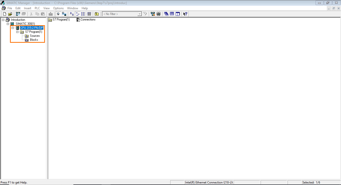
Open the “Blocks” section. Here, you will find two default elements: System data, where essential data for the system’s operation are stored. And OB1 (Organization Block 1), which is the main cyclic execution loop (Where your main program will be actually executed).

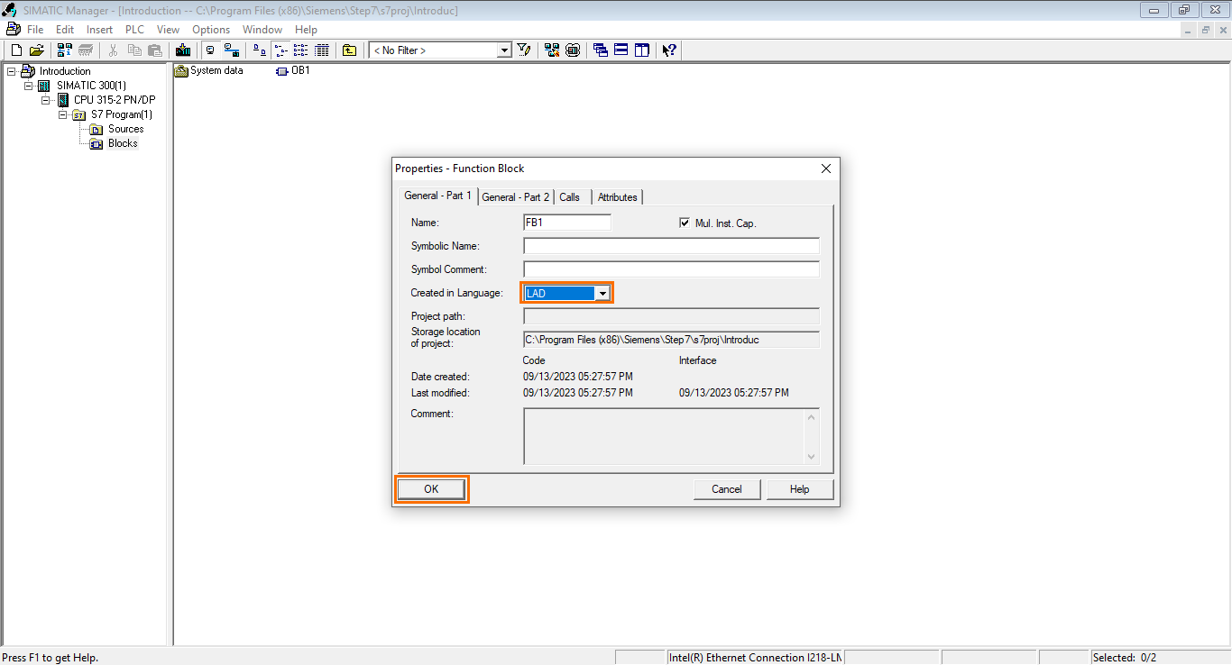
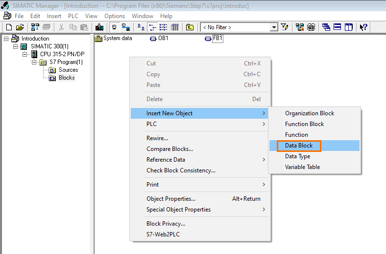
We will create A Function Block and a Data Block for this example. However, we won’t cover the actual programming, which will be covered in the SIMATIC Manager programming tutorial. To create a new block, right-click somewhere in the workspace, then go to “Insert New Object.” Here, you will find all the blocks available to create. Select “Function Block.”

A properties window of the FB will open. Be sure to select “LAD” as the language and click on “OK.”
Once done, a new Function Block (FB1) will be created.
After that, repeat the previous operation to add a Data Block.
Once again, a properties window will open. Ensure the DB type is set at “Shared DB” (Global DB).
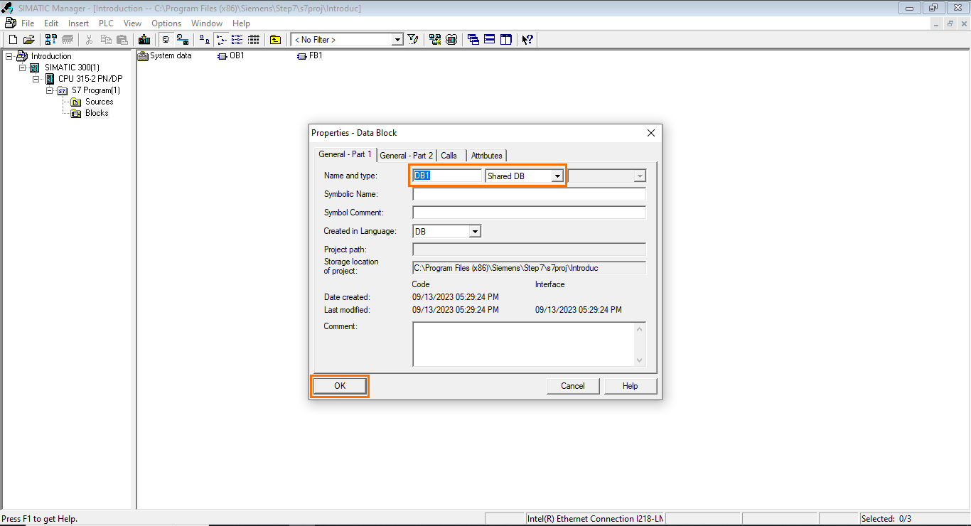
Once done, a new Data Block (DB1) is created.

Downloading and uploading the program
We have so far covered the primary steps when creating an automation project. After that, the last step would be to transfer the project containing the programs to the PLC. We need to have a physical or virtual PLC connected to this. I am using a virtual PLC (PLCSim) in the background to enable the downloading. The SIMATIC Manager simulation tutorial provides more information about the virtual PLC. Select the station in the project tree and click the “Download” button.
Wait for the download to be complete.
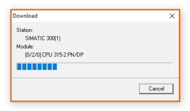
And we are done; the program has been downloaded to the PLC.
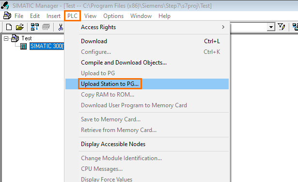
It is also possible to retrieve the program from a PLC. To do this, create a new project, open the PLC menu, and click “Upload Station to PG…”
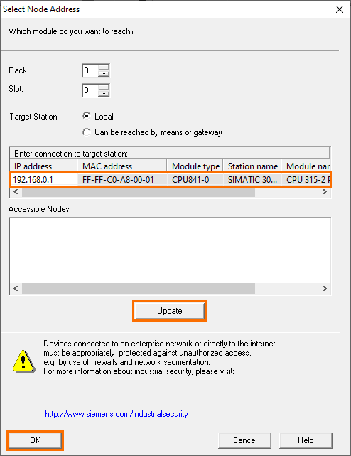
A “Select Node Address” window will open, where you can search and select the PLC to upload from. You can update the accessible devices list by clicking on “Update.” Once the desired PLC is found, select it and click on “OK.”
The loaded station will appear in your new project containing all the configurations and programs inside the PLC.
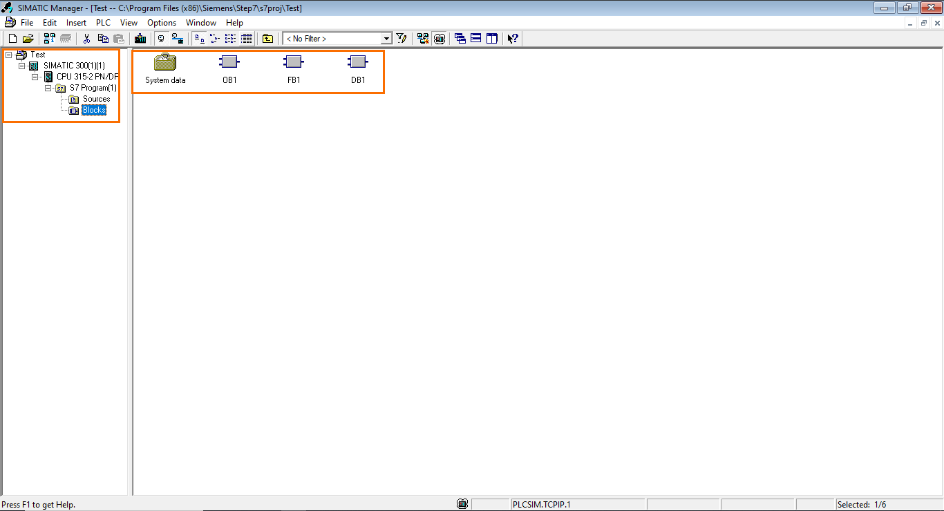
Figure 5.5: .
Conclusion
This tutorial taught you how to navigate and utilize Siemens' SIMATIC Manager effectively for programming S7-300 and S7-400 PLCs. We began by covering the essential steps of project creation, providing an in-depth look at the software's main interface. We then dived into hardware configuration, demonstrating how to add and set up PLC stations and modules. Following that, we explored network communication through PROFIBUS, illustrating how to configure connections between the PLC and other devices. Additionally, we introduced program block management, highlighting the four primary types of program blocks and explaining how to create them. Finally, we discussed the crucial processes of downloading and uploading programs to and from the PLC, completing your comprehensive understanding of SIMATIC Manager's functionality.
SIMATIC Manager has proven to be a simple, intuitive, and user-friendly tool throughout this tutorial. Its interface is designed to streamline the configuration and programming of PLCs, making it accessible even for those new to automation engineering. With its straightforward approach to hardware setup, network communication, and program block management, SIMATIC Manager empowers engineers to efficiently and confidently work on Siemens S7-300 and S7-400 PLCs.
