An Introduction to Siemens TIA Portal’s Software Units

Introduction
Managing large and complex systems with multiple interconnected components in modern automation projects can be challenging. Engineers often face the dilemma of efficiently programming and accessing different parts of the same machine, especially when collaborating simultaneously. This is where TIA Portal's Software Units come into play, offering a powerful solution to tackle this problem.
Software Units in TIA Portal enable engineers to create multiple independent software sections within a single PLC. Each Software Unit acts as a self-contained program, similar to having multiple PLCs within a single controller. Engineers can now create individual Software Units for different parts of the automation process, providing a modular and organized approach to programming. By segregating the functionalities into Software Units, engineers can work on specific sections simultaneously without interfering with others, improving collaboration and maintenance.
In this tutorial, you will learn how to utilize Software Units effectively in TIA Portal for complex automation projects. We'll start by creating a new project and adding a compatible CPU. Once the station is set up, we'll access the Software Units section in the project tree. Then, we'll create two Software Units for a water treatment station, representing the Coagulation and Flocculation parts, respectively. We'll explore how to add and configure program blocks within each unit and establish communication using relations.
Prerequisites
To follow this tutorial, you will need an installation of TIA Portal v17 or higher. We will be using the latest versions to date, but you can use any other version. No additional hardware or software is required.
TIA Portal’s Software Units
Let’s start by creating a new project in TIA Portal. After that, we need to add a device. Click on “Add new device” in the Project tree.

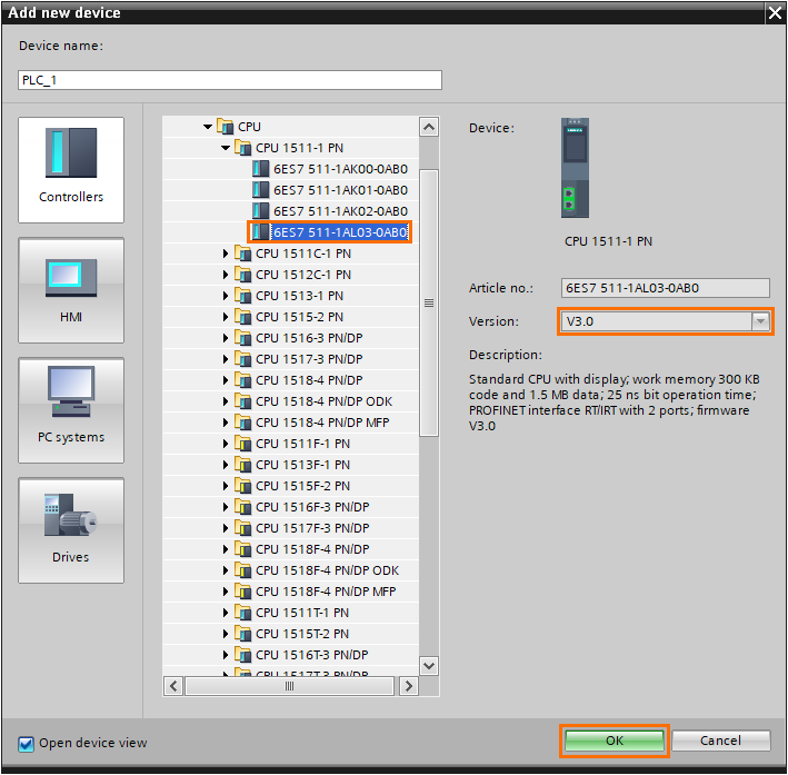
Select a CPU with a firmware version 2.6 or higher to access Software Units. Here we’ll be using a 1511-1 CPU with version 3.0. Once done, click on “OK.”
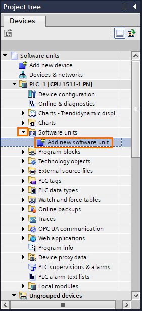
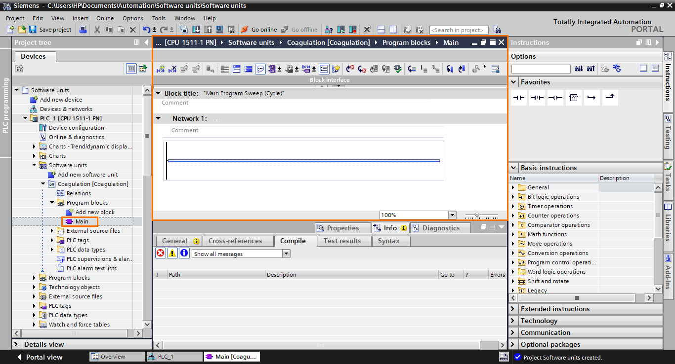
The station is added to the project. Inside the CPU folders, you can find a Software Units section in the project tree.

Open the Software Units section by clicking on the small black arrow on its left.
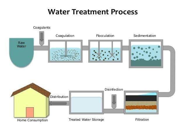
Software units allow you to create multiple software sections that are executed and accessed independently. "For example, you may encounter a scenario in which the PLC controls a machine that is composed of multiple components such as a water treatment station. It is composed of multiple tanks where water receives different treatments (Coagulation, flocculation, sedimentation, filtering, disinfection) sequentially.
Let’s say we have only one PLC controlling this whole water treatment section. Instead of merging all the programs of all the different parts in one program, you can create a Software Unit for every part of the process. Each part will be executed independently in its own OBs and engineers can access each Software Unit and do modification or maintenance simultaneously as if it was different PLCs. In a sense, it is as if Software Units allow you to have multiple projects in the same PLC.
We will take the water treatment station as an example and create two Software Units: One for the Coagulation part and the other for the Flocculation. Let’s create the first Software Unit. Click on “Add new software unit.”
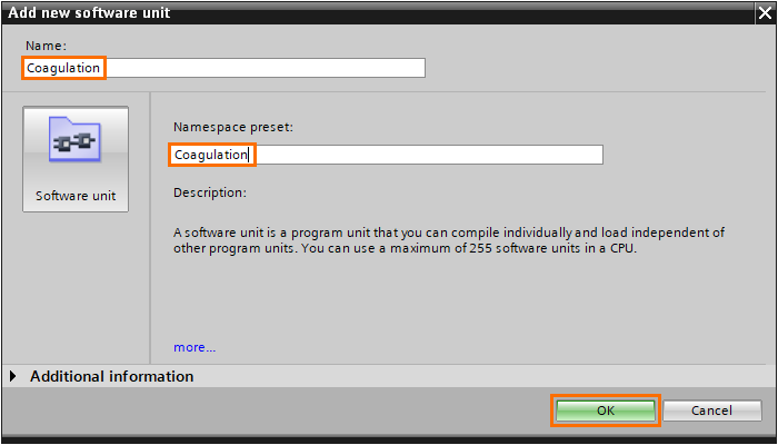
A small window will open where you can define a name for the Software Unit and a namespace preset.
A namespace preset allows you to have blocks with the same in different software units. All blocks with the same namespace belong to the same independent environment.
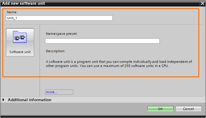
Give a name to the Software Unit. For clarity, give the same name to the namespace.
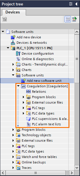
Once the unit is created, it will appear in the Project tree. Open it by clicking on the small black arrow. You should find all program components (Program blocks, External source files, PLC tags, PLC data types, PLC supervision, and PLC alarms).
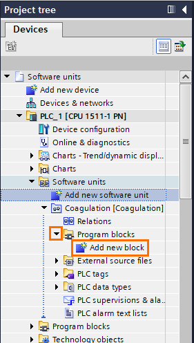
Let’s add a small program. Open the “Program blocks” folder and click on “Add new block.”
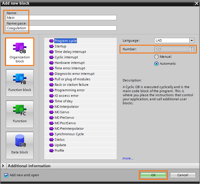
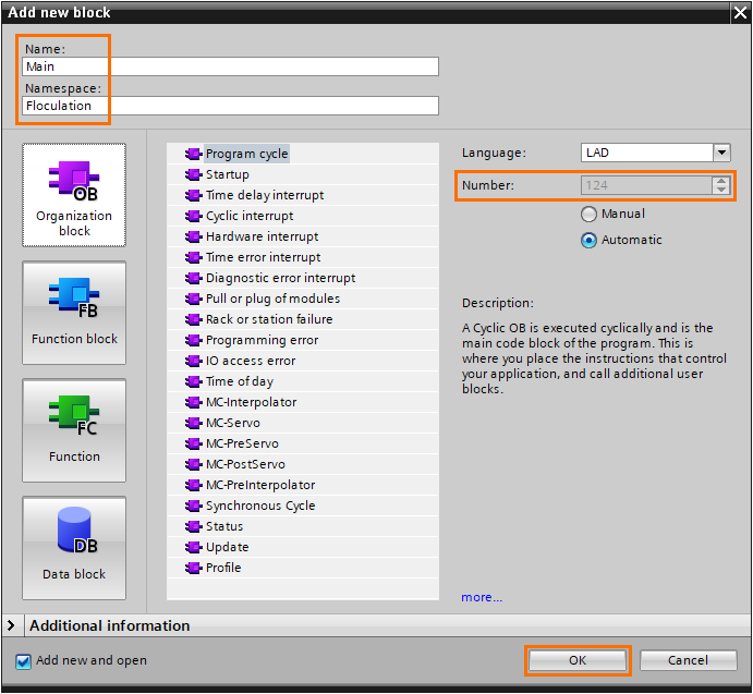
The first block we have to add is a main program (Organization block). In the regular program, the main program would be the OB1, for example. Here, Software Units OBs start at OB123. OB1 is still reserved for the regular program. Give a name to the block (it should have the namespace as the unit). Select “Organization block” and click on “OK.”
The main program is created. By opening it, you should find a regular programming interface. The unit’s program will be executed here.
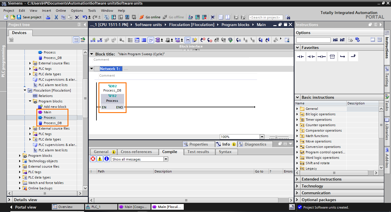
After that, create a Function Block (FB), name it “Process”, and call it in the main program (Create the instance DB too).

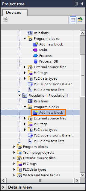
Let’s add a second Software Unit. Click on “Add new software unit.”

The second unit will be for the flocculation. Give the unit its name and namespace preset.

Add a new main block in the flocculation unit like we did previously for the coagulation unit. Open the “Program blocks” folder in the Flocculation unit and click “Add new block.”
As we did before, the first block we’ll add is the main block. Since it’s in a different namespace, we can give it the “Main” name without conflict with the coagulation unit’s main program.
Add “Process” FB and call it in the main program. Then, call it the main program (and create its instance DB).
We now have two software units with independent programs. Normally programs in different units can't interact. They are totally separated and independent environments. We may need to communicate some data from one unit to another. For this, we use Relations. Let’s create a boolean that will serve as a flag to indicate the process is done in the coagulation unit to the flocculation unit.
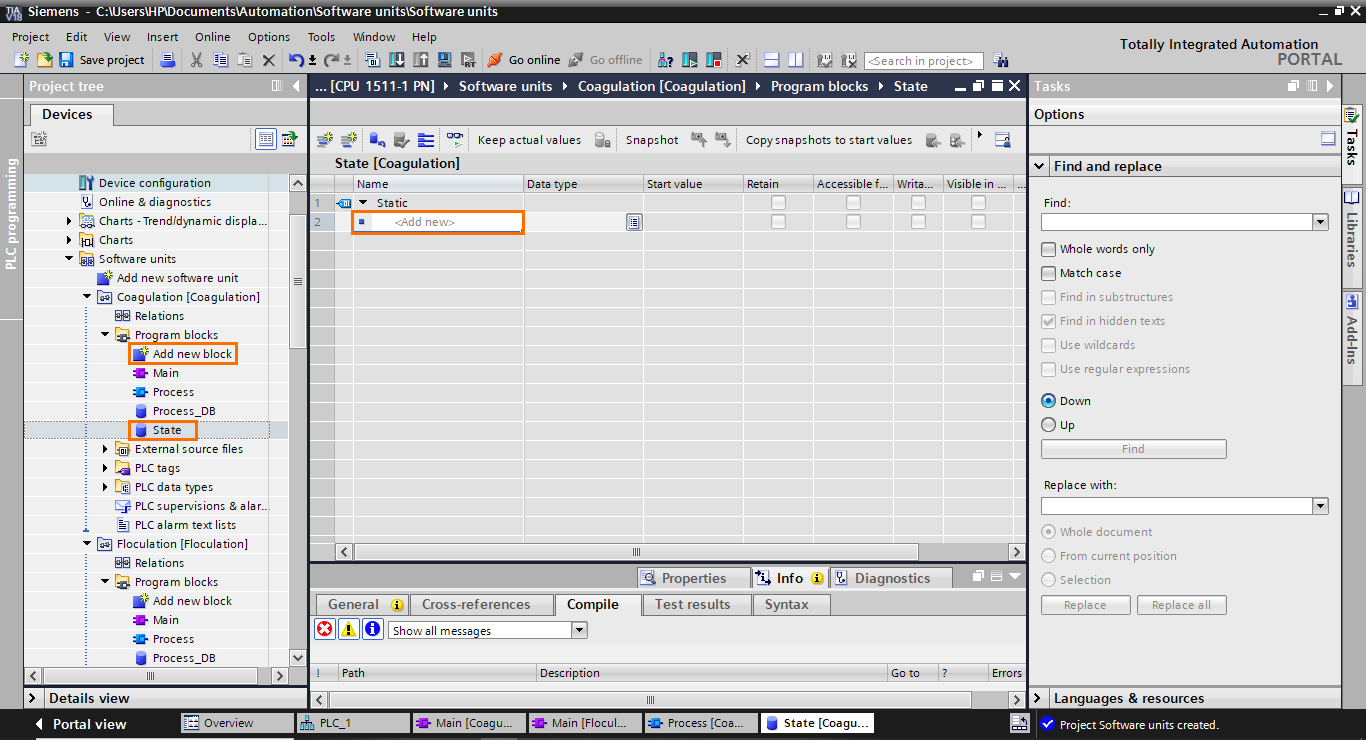
Create a Data block in the coagulation unit, name it, open it, and click on “Add new”.
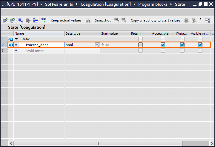
Create a boolean element and name it “Process_done”
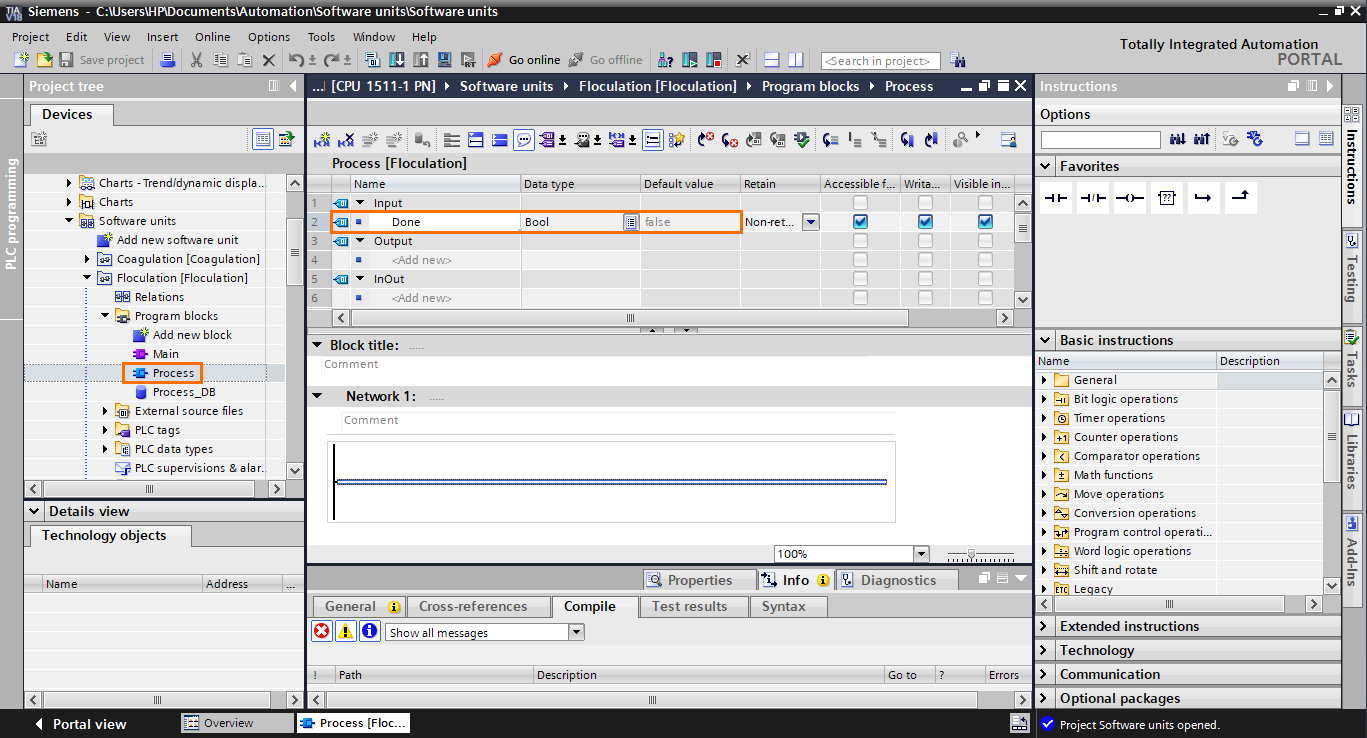
Now let’s go back to the Process FB in the flocculation unit and add an input to the FB’s interface. Name it “Done”
Always in the flocculation unit, update the FB call in the main program. Then, select the DB we created before and drag and drop the “Process_done” element (from the details view) to the FB’s input.
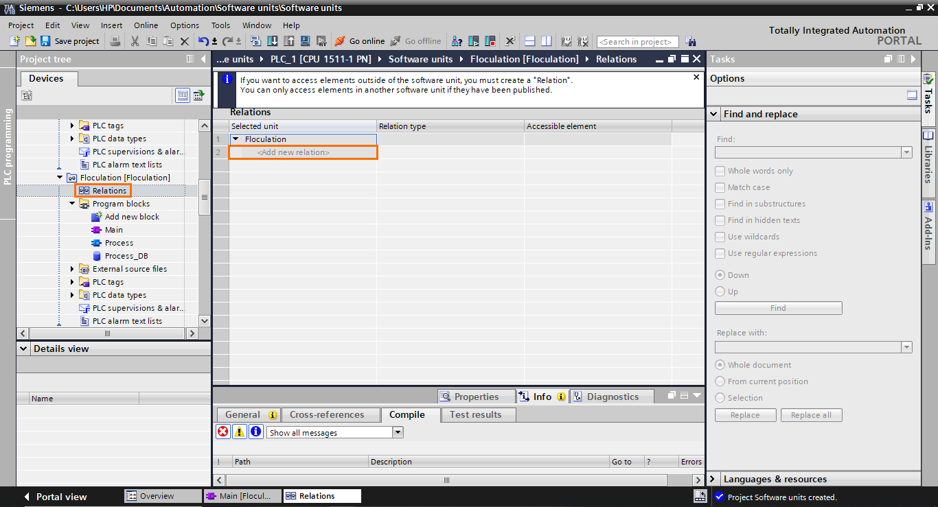
As you can see, we can’t use an element from one unit to another (red color). To remedy this, we have to create a relation between the two units. Open the “Relations” section of the flocculation unit.
Relations work like imports. If you create a relation in Unit A and link it to Unit B, You will be able to use Unit B’s elements in Unit A but not the other way around. Also, you cannot create a relation in Unit B if there’s one in Unit A (no circular relations). So here, by creating a relation in the flocculation unit, we will be able to use elements from the coagulation unit.
Click on “Add new relation”. By default, the relation type is set to “Software Unit” which is what we want.

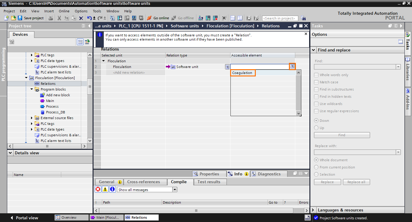
By clicking on the button in the “Accessible element”, you can select the unit you want to be linked to.
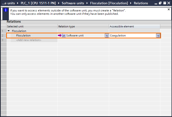
Now we have created a relation in the flocculation unit, and we linked it to the coagulation unit.
Software Units are the only type of object you can access with relations. You can also access global DBs in the regular program and technology objects. Click on the button in the relation type section to have a look at the other accessible types.

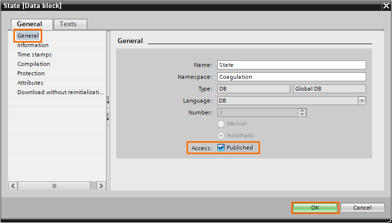
Now that we created a relation, there’s one last step we need to perform to allow the program to access the DB element. Creating a relation is not sufficient. We need to publish the desired block so it can be accessed through the relation. For this, right-click on the element we want to publish (Here the “State” DB) and go to its properties.

In the general section of the properties, check the “Published” checkbox.
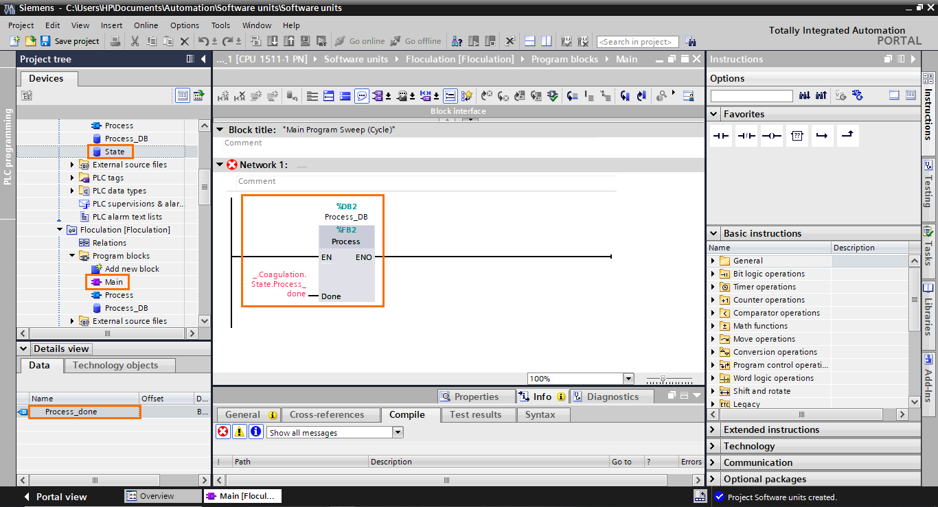
If we go back to the main program of the flocculation unit, we will find that the element from the DB in the coagulation unit is now accepted as input in the FB block.
Conclusion
In this tutorial, you learned how to effectively use Software Units in TIA Portal to manage complex automation projects with multiple engineers. We started by creating a new project and adding a compatible CPU with firmware version 2.6 or higher. Next, we explored the Software Units section in the project tree and created two Software Units for a water treatment station, representing the Coagulation and Flocculation parts. Through step-by-step guidance, we discovered how to add program blocks, such as main programs and Function Blocks, to each unit and establish communication between them using relations. This modularity and independence of Software Units provided a streamlined approach to programming, allowing engineers to work simultaneously on different parts of the process without conflicts.
Using Software Units in TIA Portal offers many advantages for automation engineers. It enables efficient organization and management of complex projects, allowing the creation of independent software sections that can be modified and maintained individually. This modularity promotes collaboration among engineers, as they can work simultaneously on different aspects of the process, leading to faster development and reduced project lead times. Moreover, Software Units facilitate code reuse, as well-tested and verified functionalities can be easily replicated across multiple projects. With Software Units, engineers can efficiently handle large-scale automation systems, leading to enhanced productivity, reliability, and maintainability in industrial automation projects.
