An Introduction to CFC [Control Flow Chart] PLC Programming in TIA Portal

Introduction
In modern industrial automation, the need for efficient and intuitive control logic programming has become increasingly crucial. Traditional text-based programming languages, while powerful, can be complex and challenging to visualize, especially for complex control strategies. This creates a significant problem for automation engineers, leading to longer development times, increased debugging efforts, and reduced overall productivity. To address these challenges, Siemens has introduced the Continuous Function Chart (CFC) language in their TIA Portal software, providing a graphical programming approach that allows engineers to design control logic visually using interconnected function blocks.
CFC, standing for Control Flow Chart, is a powerful graphical programming language that simplifies control logic design within Siemens' TIA Portal environment. It employs interconnected function blocks to visually represent the control flow, reminiscent of electronic or logic-based diagrams. By utilizing this visual approach, automation engineers can intuitively design intricate control strategies by arranging and linking these function blocks. Additionally, the CFC language enables the creation of multiple charts or sub-charts that can be interconnected, providing a modular and scalable approach to programming complex control systems. Together, these features make CFC a valuable tool for developing sophisticated control logic efficiently and with greater clarity.
In this tutorial, you will learn how to use the CFC language in Siemens' TIA Portal to program a simple motor control function. The tutorial will start by guiding you through creating a new project. Then you will then learn how to access and utilize the CFC charts section in the project tree to develop and manage CFC charts. Afterward, you will be shown how to integrate function blocks into the CFC chart, linking the inputs and outputs to the relevant tags. Finally, you will compile the chart's organization blocks and use a simulation instance to test the motor control program's execution, verifying that the motors respond correctly to the input signals.
Prerequisites
To follow this tutorial, you will need an installation of TIA Portal and CFC. PLCSim Advanced is optional and can be replaced with the regular TIA Portal’s PLCSim. We will be using the latest versions to date, but you can use any other version. No additional hardware or software is required.
The CFC language in TIA Portal
Let’s start by creating a new project. After that, add a CPU of your choice. Here we will be using a 1511 CPU. If you installed CFC (with its licenses), you will find a “Charts” section in your project tree where you can create and manage CFC charts. Double-click on “Add new chart.”
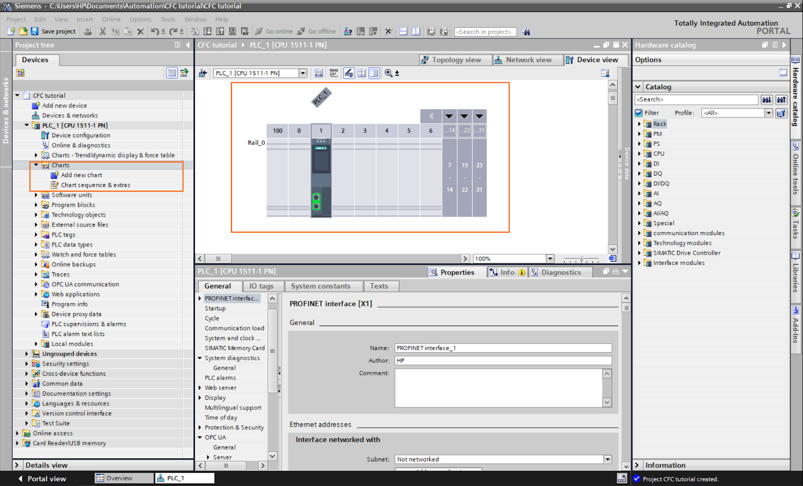
Figure 1.1: Creating a new project and accessing the CFC charts.
CFC is a graphical programming language. It uses interconnected function blocks to represent control logic visually. The charts' visual style is similar to electronic or logic-based diagrams. You can design complex control strategies intuitively by arranging and linking these blocks. Also, you can create multiple charts or sub-charts and connect them.
The CFC interface consists of five parts:
- Inputs zone: All inputs of your program will be placed in this zone. You can link them from here to other blocks.
- Workspace: Space where you put and link blocks.
- Output zone: All program outputs will be placed in this zone. You can link them from here to other blocks.
- Chart interface: Here you can define the chart’s interface (inputs, outputs…etc).
- Instructions: List of the instructions you can use with the CFC language.
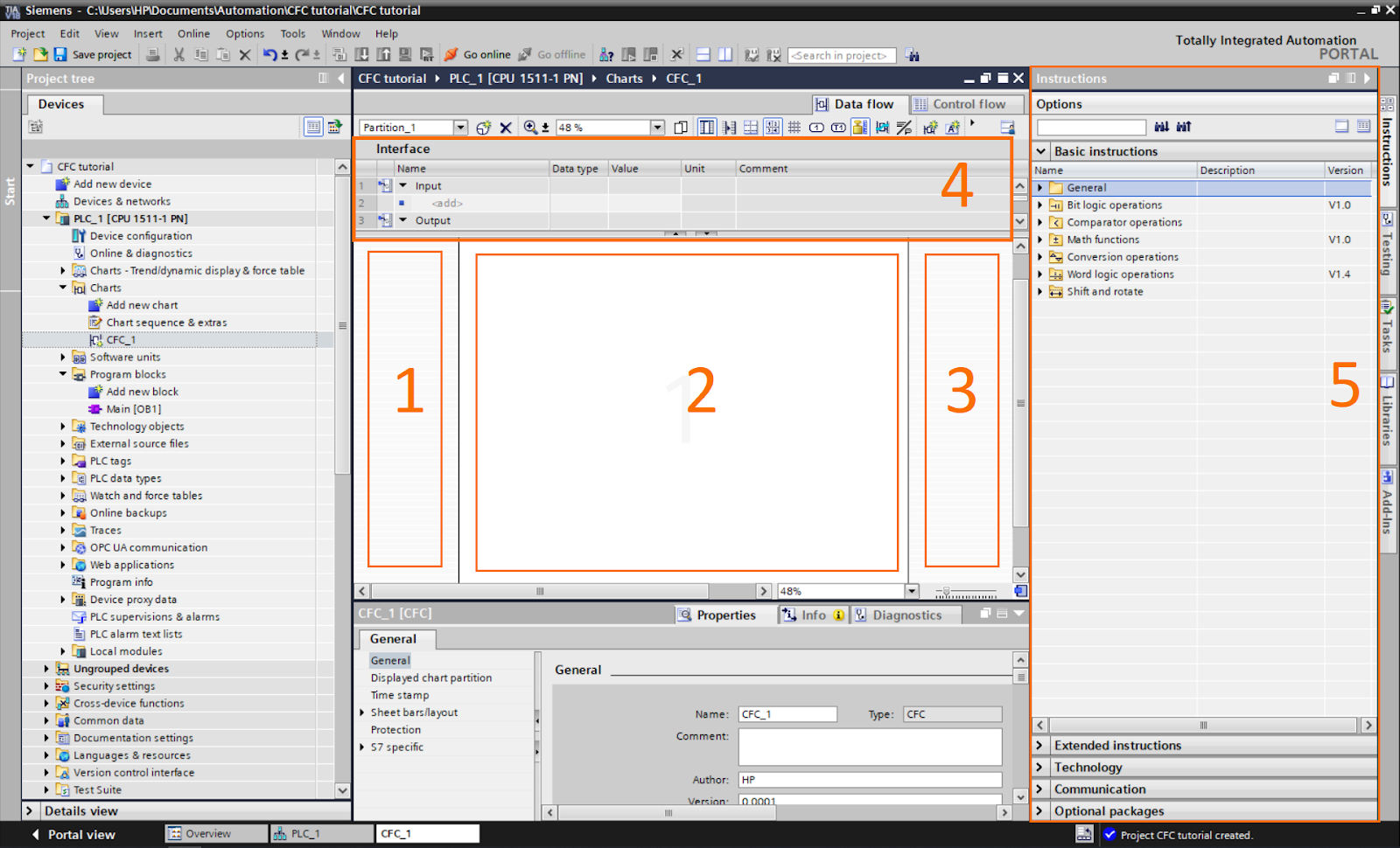
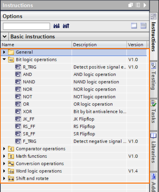
The instruction list contains all the tools you need for programming like any other language. The instruction set available in CFC is similar to the FBD set.
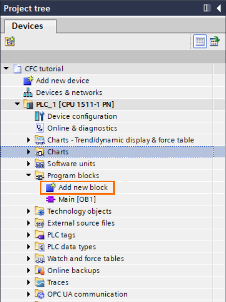
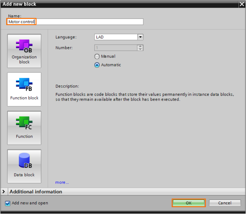
Before programming the CFC chart, let’s create an FB we will use inside it. Go to the “Program blocks” of the project tree and click on “Add new block”.
Select “Function block” and give a name to the block.
We will build a simple motor control function. This function will be used multiple times to control four motors. Create the following program.
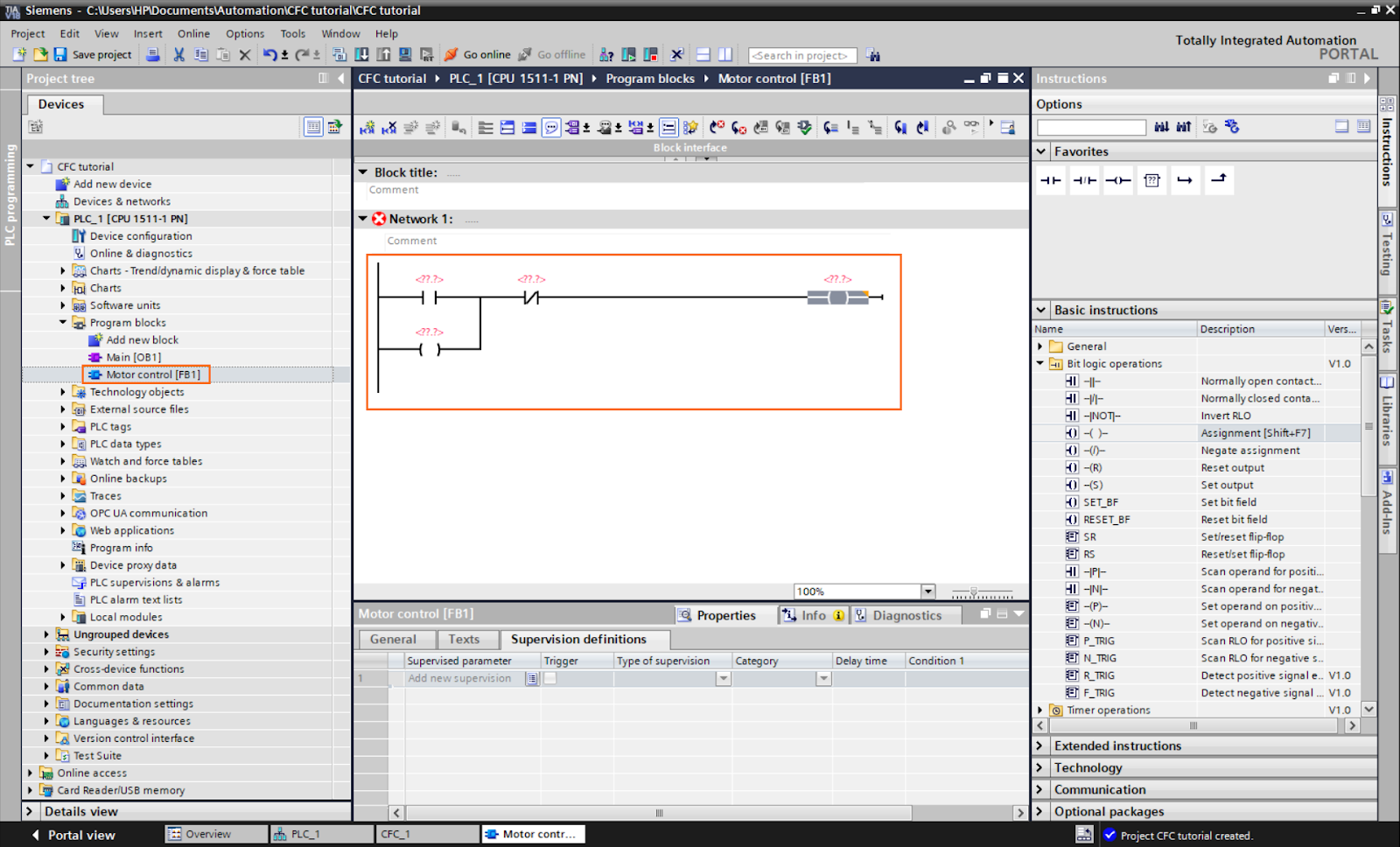
Then, add the following inputs/outputs in the FB interface and add them to the program as follows.
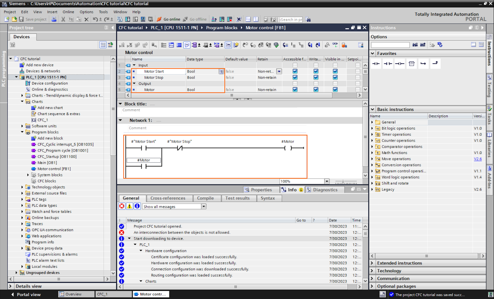
After that, we need to define the tags for the four motors. Open the default tag table in the project tree.

And create the following tags.
We create the first’s motor tags, we can duplicate them to create the three others automatically. Select the tags, then, click on the bottom left corner of the selection and drag down nine lines.
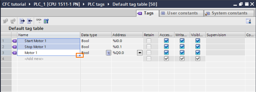
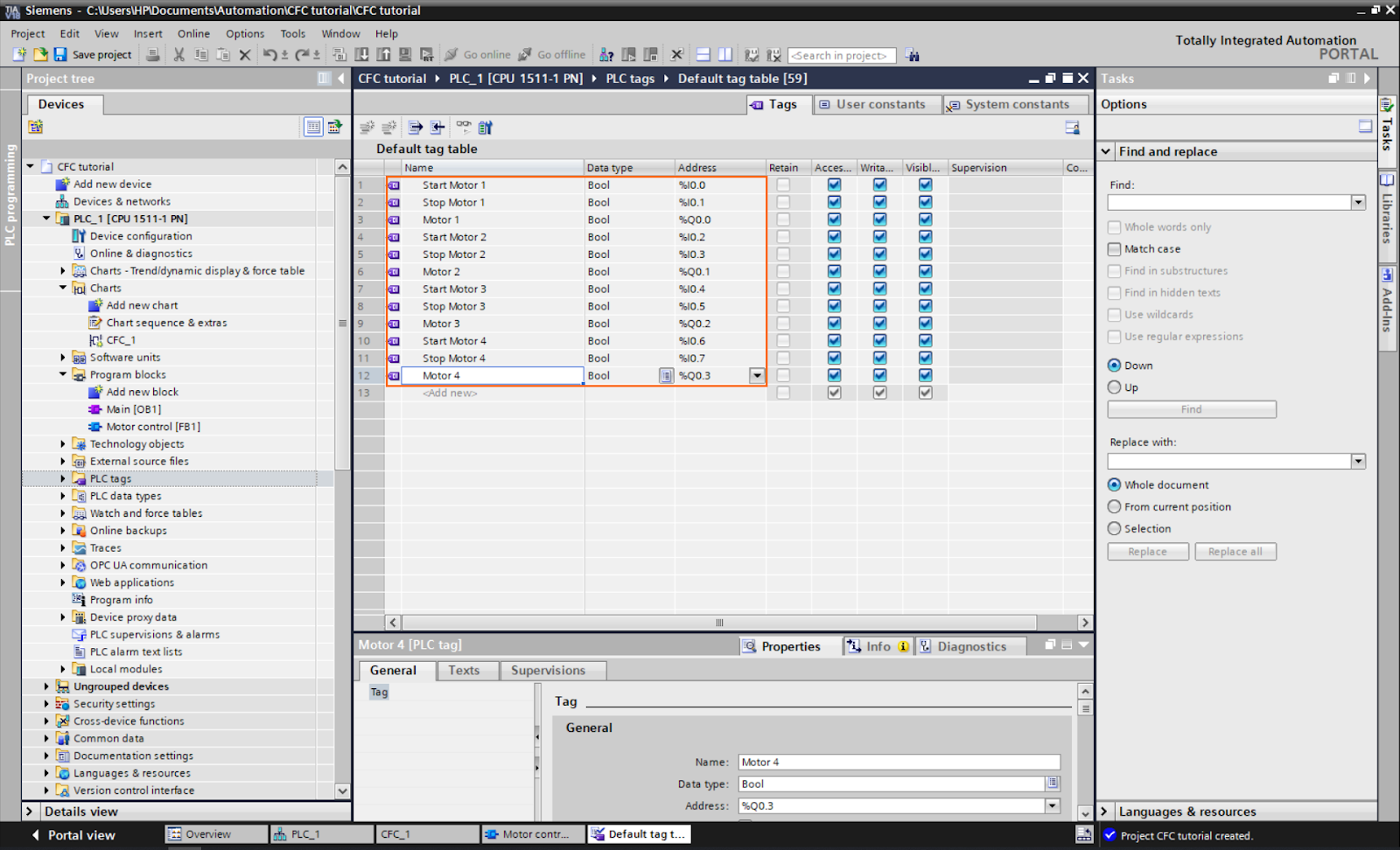
You should obtain a tag list complete with the right numbers as shown below.
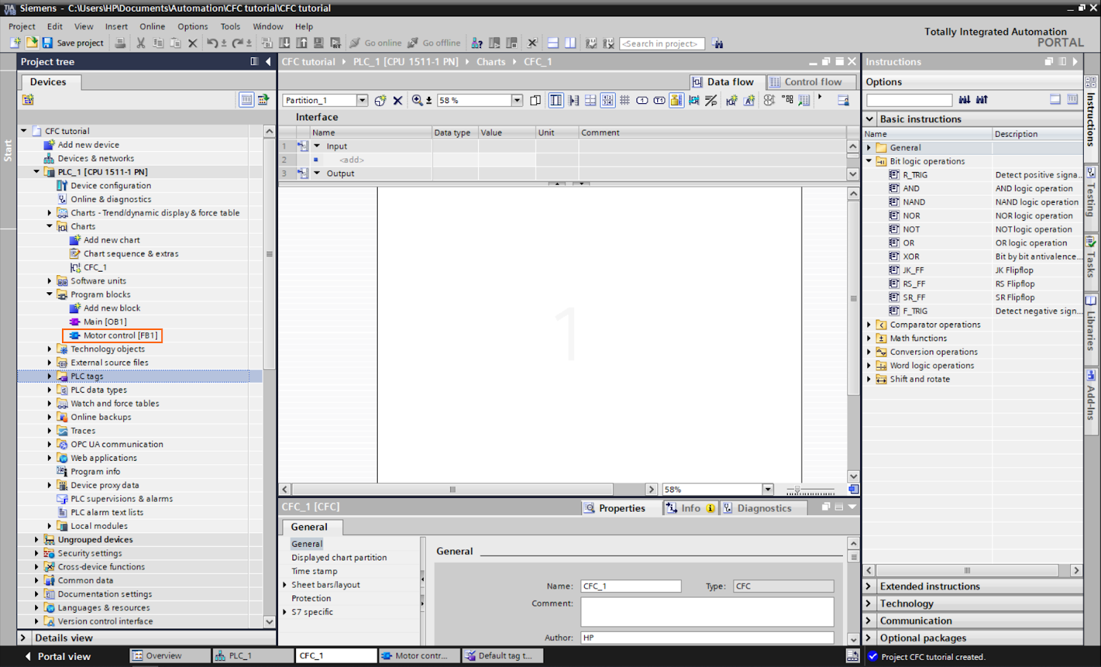
We have now the tags we need for the four motors. Go back now to the CFC chart and select the “Motor control” FB in the project tree and drag it to the workspace.
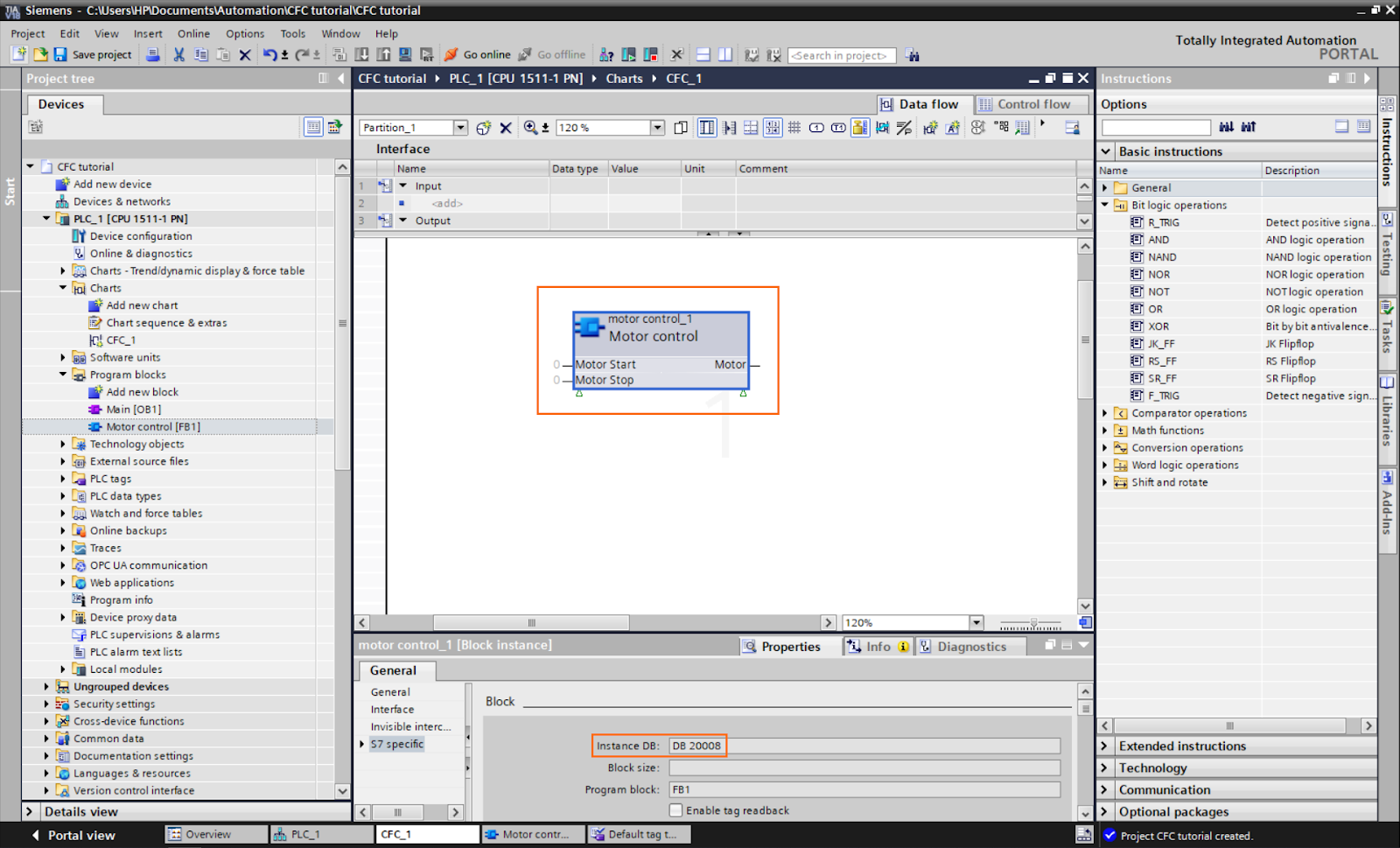
The block should appear inside the chart. As you can notice, the block has the two inputs and the output we created in its interface (Motor start, Motor stop, and Motor). It also has an instance DB created automatically.
To add tags to the I/Os, drag and drop them from another section or right-click on it and select “Interconnection to operand.”

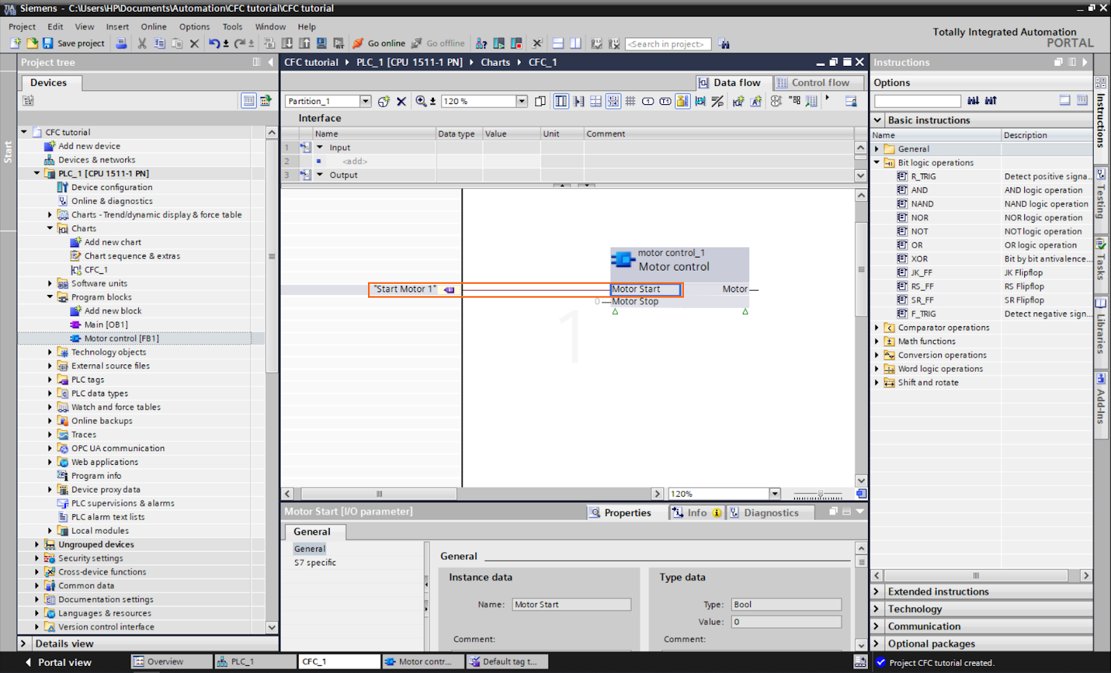
A field appears where you can type the tag you want to add. By typing the beginning of the tag, it should appear in the list. Select “Start motor 1”.

The “Start motor 1” appears in the inputs zone, and it becomes linked to the FB’s input.
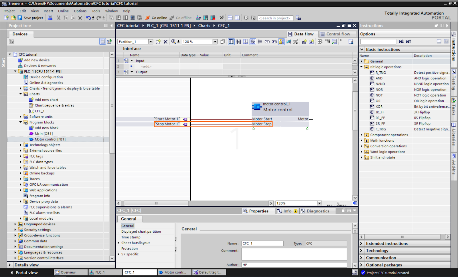
Repeat the same step to add the “Stop motor 1” tag to the Motor stop input of the FB.
And repeat them for the “Motor 1” output. This time, the tag will appear in the outputs zone.
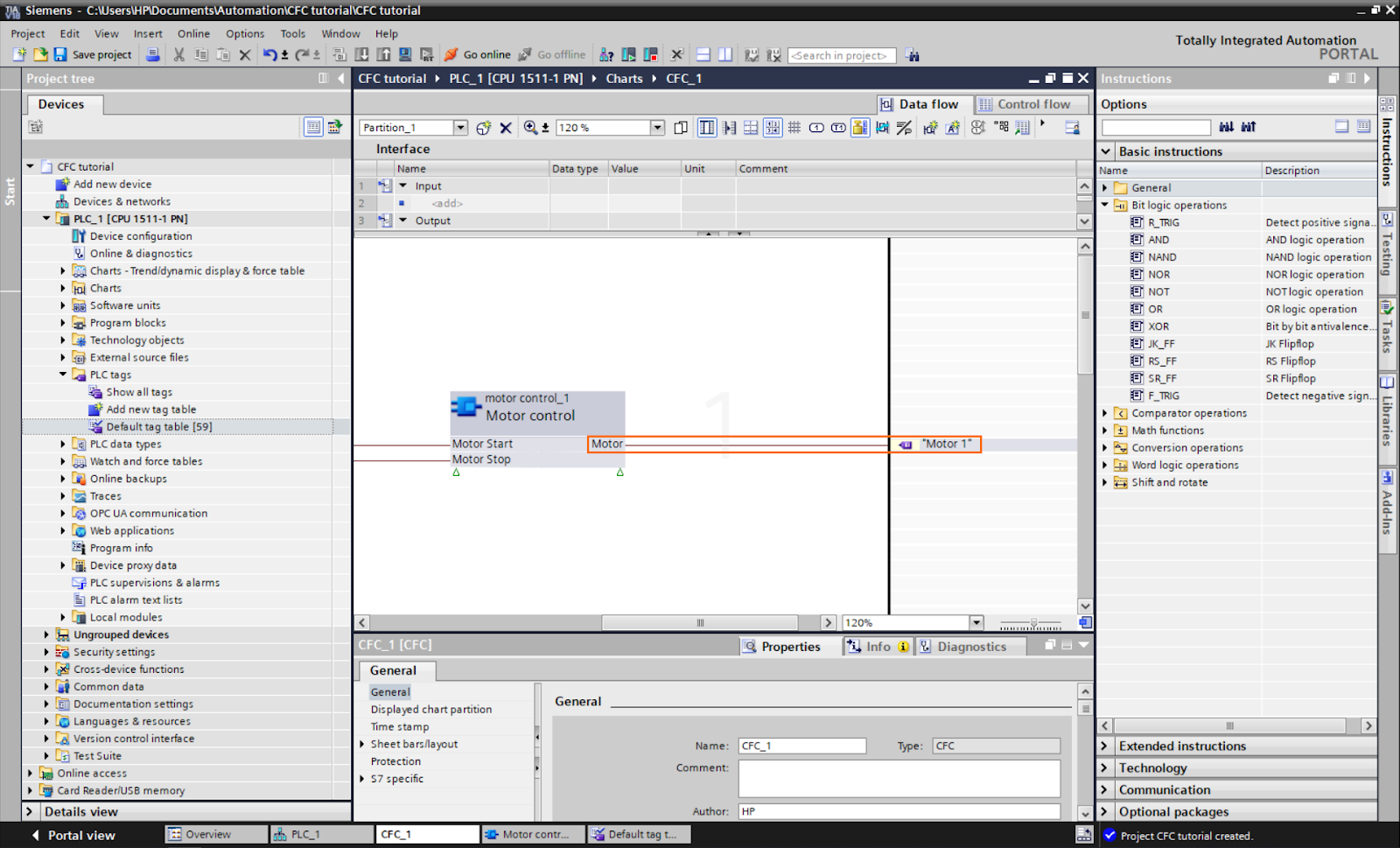
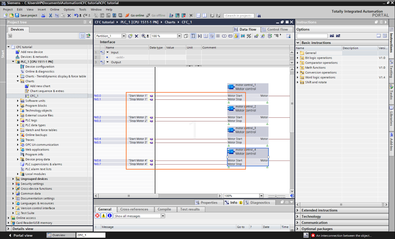
You should obtain a block linked as follows. To create the other three blocks, we can copy this one and paste it three times. Select the FB and copy it.

And paste it three times to obtain three FBs, as shown below.
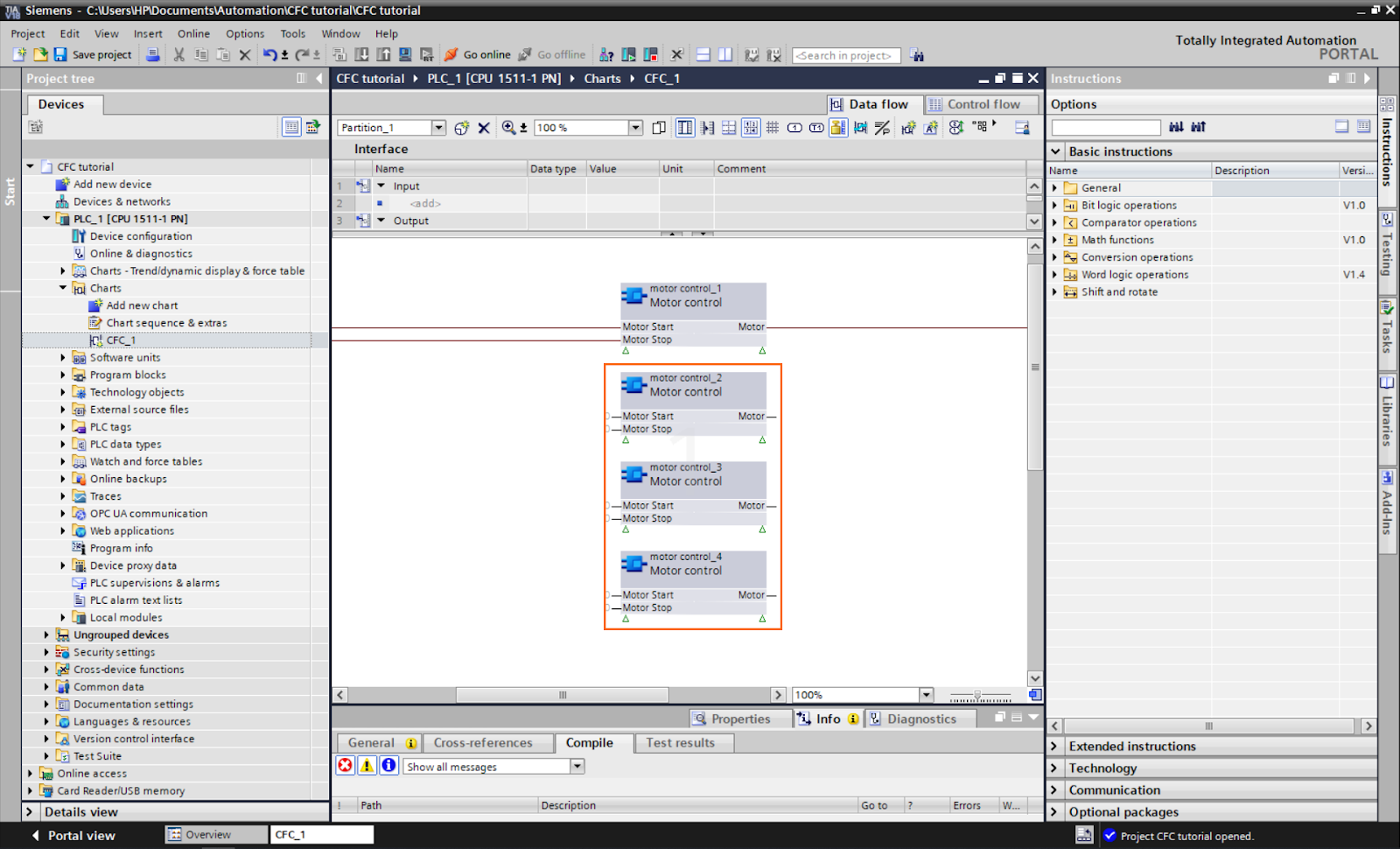
Then, add all the inputs as we did before to all FB blocks.
And do the same for the outputs.
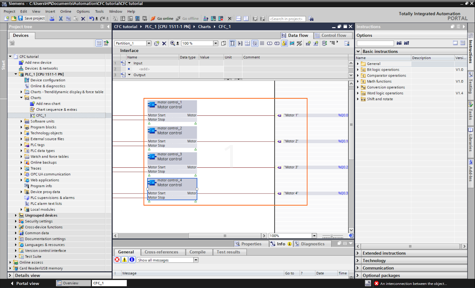
The program is now done. Click the “Compile” button to generate the chart’s Organization blocks. These blocks will contain the program in the CFC charts and will be executed here.

You can create a simulation instance to test the program’s execution. Here we’ll be using a PLCSim Advanced instance, but you can use a regular PLCSim instance instead. Create the instance and load the program into it.

We will use a watch table containing all the tags we used for the testing. Create the following watch table.

Run the watch table in visualization mode and change the tags’ values as shown below.
As you can see, all motors work as intended. Changing the value of the “Start motor” tags to 1 does turn on its associated motor. Doing the same for the “Stop motor” tags but to 0 does turn off the motor.
Conclusion
In this tutorial, you learned how to utilize the Continuous Function Chart (CFC) language in Siemens' TIA Portal to create a simple yet effective motor control function—starting with the creation of a new project and accessing the CFC charts section to design control logic visually using interconnected function blocks. You learned how to define a custom function block for motor control, create tags for the motors, and integrate the function block into the CFC chart by linking inputs and outputs to relevant tags. We also covered the compilation of organization blocks and using a simulation instance to test the motor control program's execution.
Adopting the Continuous Function Chart (CFC) language in Siemens' TIA Portal offers numerous benefits that significantly improve the efficiency and intuitiveness of programming for industrial automation. CFC simplifies complex strategies by providing a graphical representation of control logic, allowing engineers to design and understand control programs more easily. The interconnected function blocks in CFC enable modular and organized programming, enhancing code reusability and maintainability. With the straightforward interface and extensive instruction set, CFC empowers automation engineers to design sophisticated control strategies more intuitively, reducing development time and debugging efforts. Overall, CFC proves to be a powerful tool that not only accelerates the programming process but also enhances the overall productivity and quality of industrial automation projects.
