An Introduction to the Function Block Diagram (FBD) Language in TIA Portal

Introduction
Industrial automation relies on various programming languages to implement control logic effectively. Among the five languages IEC 61131-3 standardized, the Function Block Diagram (FBD) is a prominent choice. This graphical programming language offers engineers a powerful tool for designing complex control sequences within the TIA Portal environment. FBD is renowned for its ability to harness predefined function blocks, encompassing mathematical operations, timers, counters, and logical functions. Operating within a visual canvas, these blocks interconnect via lines representing data flow, facilitating intricate automation systems' design, debugging, and maintenance.
The Function Block Diagram (FBD) language, part of Siemens' TIA Portal ecosystem, facilitates the creation of sophisticated control algorithms through graphical programming. With the FBD language, engineers can build control logic by selecting and connecting function blocks, creating a cohesive and efficient control sequence.
In this tutorial, you will learn how to harness the power of FBD language in TIA Portal for creating diverse control logic scenarios. You will be guided through adding new blocks, connecting function blocks, and utilizing instructions from the FBD language library. The tutorial covers three practical programs: implementing Boolean algebra, modeling linear equations, and programming a motor control application.
Prerequisites
To follow this tutorial, you will need an installation of TIA Portal. We will use the latest versions to date (v18), but you can use any other version. No additional hardware or software is required.
Programming in FBD language in TIA Portal
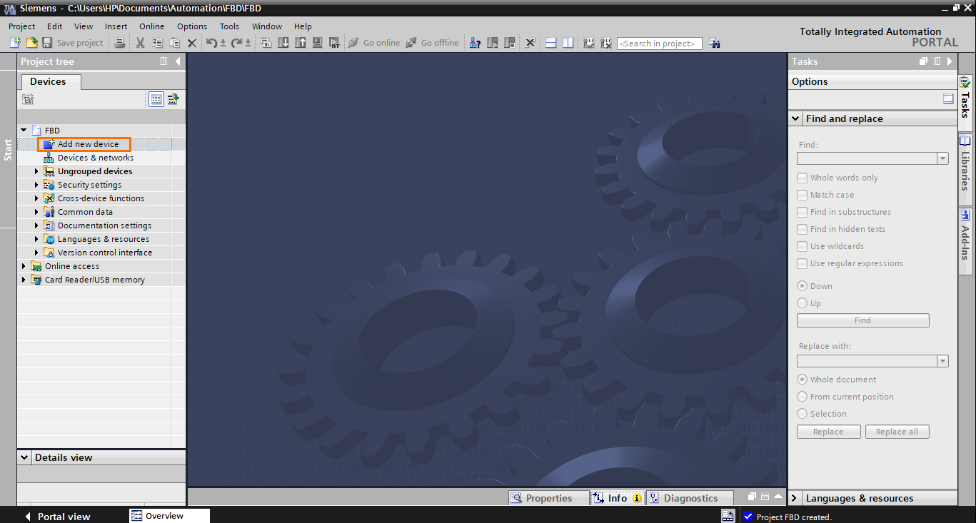
Let’s start by creating a new TIA Portal project. Once done, click “Add new device” in the project tree.
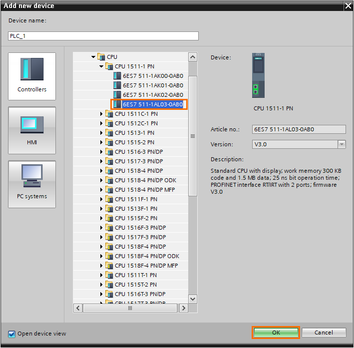
After that, you can select any CPU of your choice; FBD is supported by all Siemens PLC models. Here, we will use a 1511-1 PN CPU. Then click on “OK.”
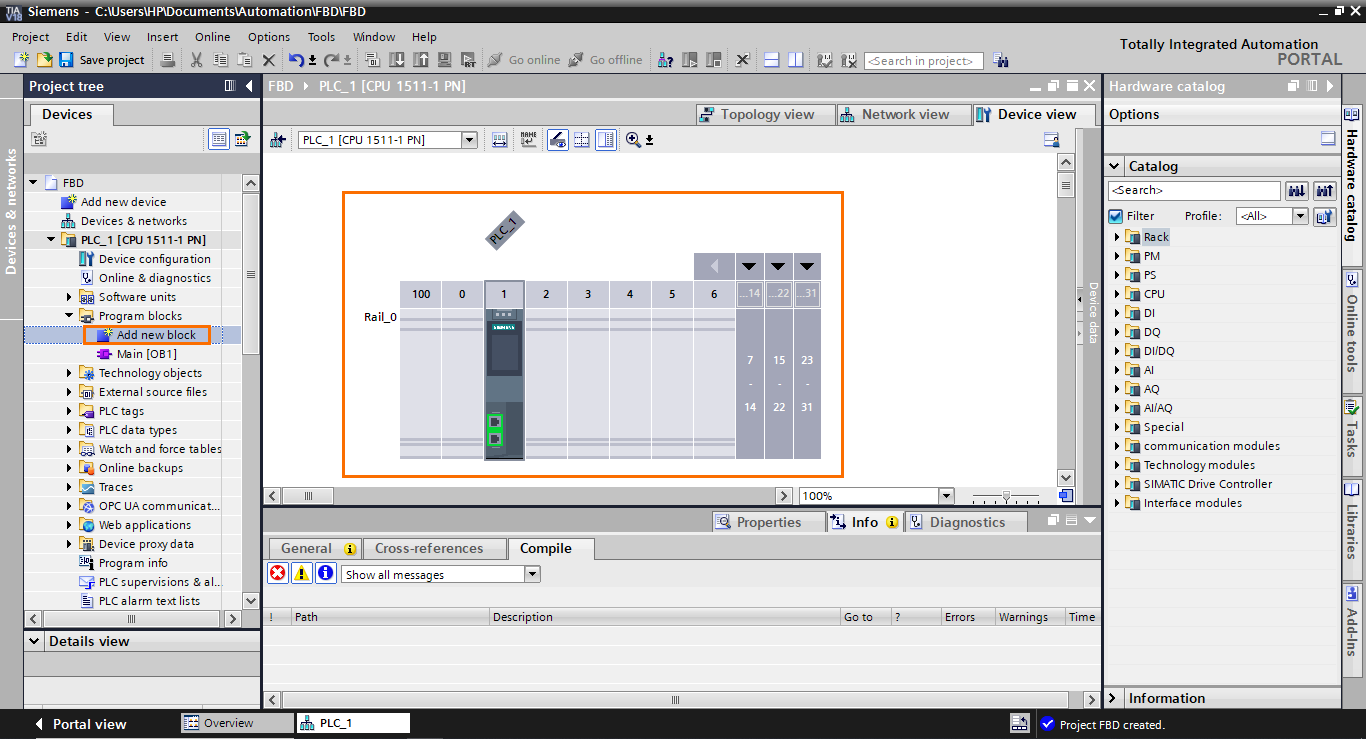
Once the station is created, we can add a new FBD program block. Click “Add new block” in the program blocks section of the project tree.
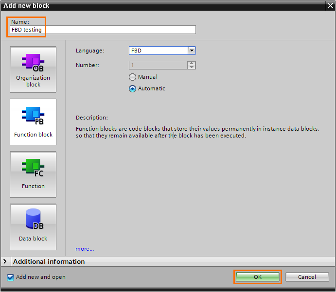
The FBD language can be used in OBs, FBs, and FCs. Here, we create an FB. In the “Add new block” window, select “Function block.” Then, open the languages list and select “FBD.”
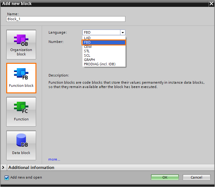
After that, give the block a name and click “OK.”
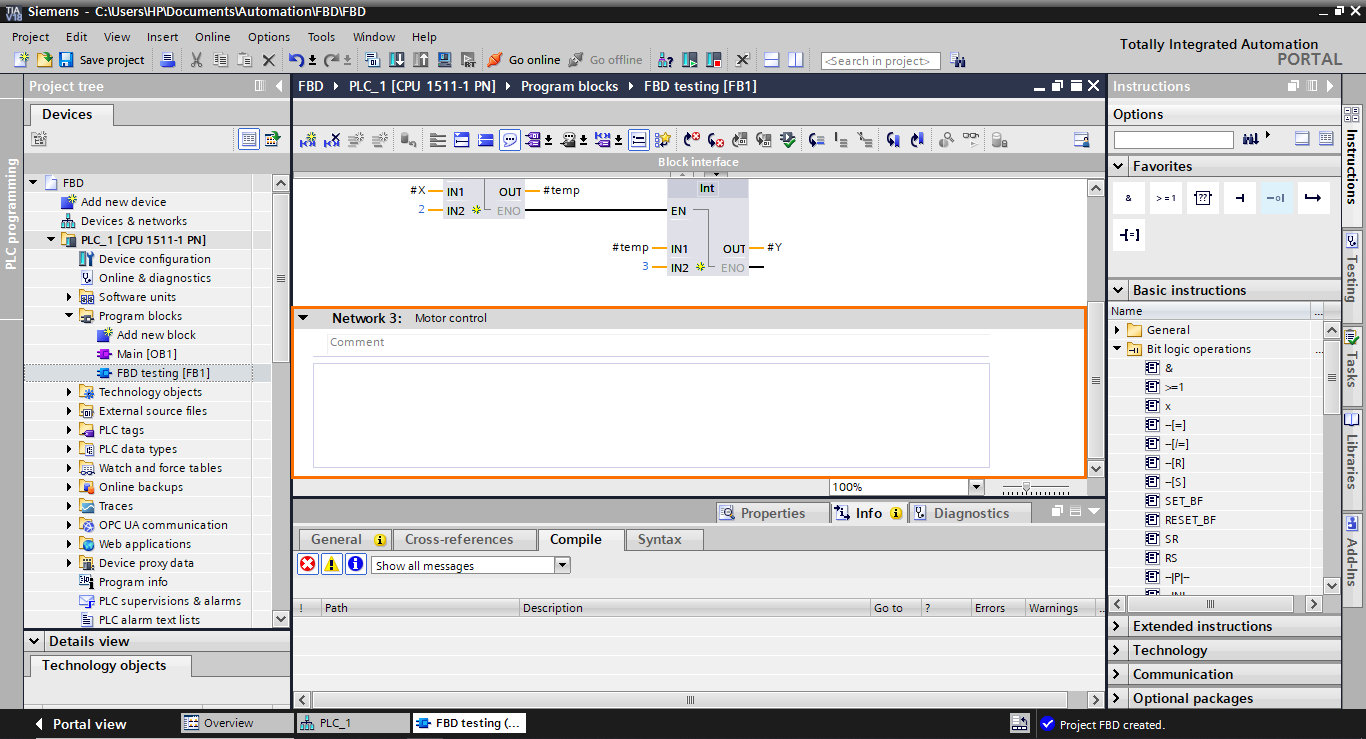
After the block is created, we arrive at the FBD programming interface.
The FBD language is a graphical language that allows you to create complex control sequences by utilizing predefined function blocks, such as mathematical operations, timers, counters, logical operations…etc. FBD operates on a visual canvas where these function blocks are interconnected through lines representing data flow. Users can design their logic by arranging and connecting these blocks to create the desired control behavior.
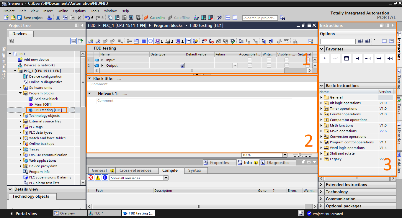
- Block interface: As with any other FB block, FBD blocks have an interface where you can define the block’s inputs, outputs, constants, temps…etc.
- Workspace: This is where you assemble and connect function blocks.
- Instructions: Contains all the function blocks available in the FBD language, such as bit logic operations, timers, math functions…etc.
To illustrate how the FBD language works, we will create 3 small programs for 3 applications. The first program will contain a boolean algebra equation. The second program will contain a simple linear math equation. The third program will contain a simple motor control application.
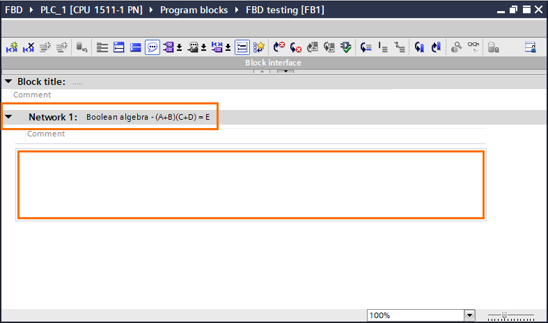
Boolean algebra
Let’s start with the Boolean algebra equation. We will model this simple equation (A+B)(C+D) = D, which can be translated to ( A OR B ) AND ( C OR D ) equals E. To do so, we will use Network 1 of the FB.
To model this equation, we will use bit logic operations only. Open the “Bit logic operations” folder in the basic instructions section. Here, you will find all the usual boolean instructions such as AND/OR operators, affectation, set, reset…etc.
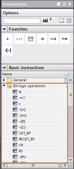
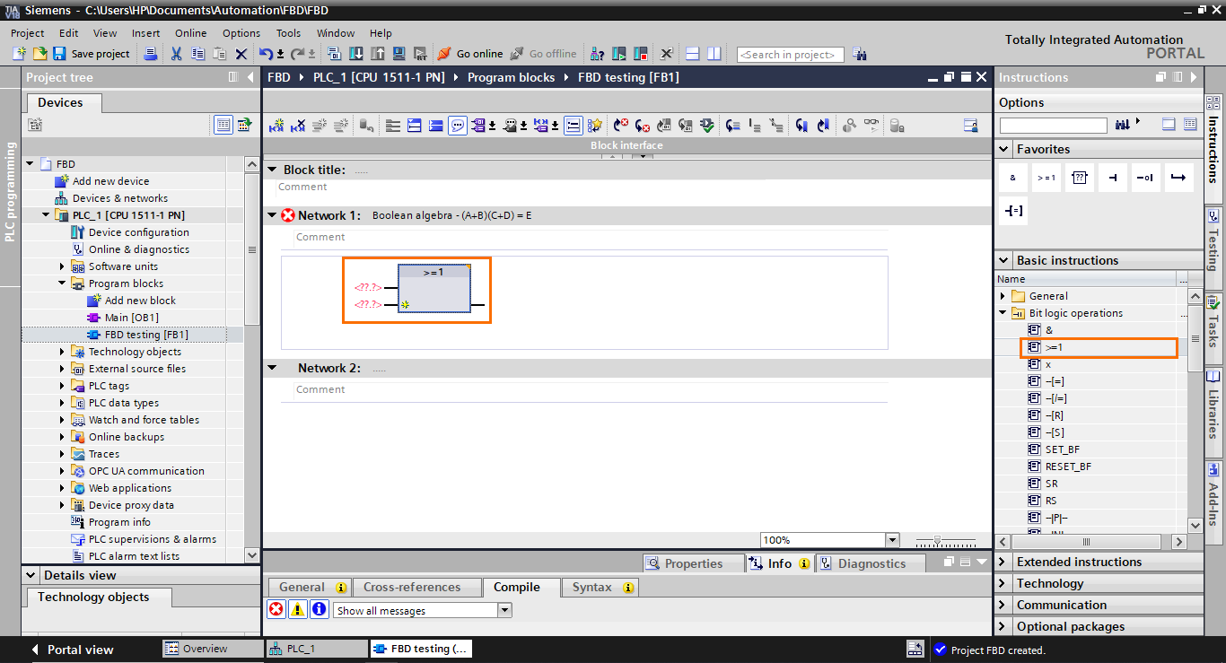
Let’s start by adding an OR operator. Select the OR operator ( >=1 ) in the instruction list and drag it to the workspace.
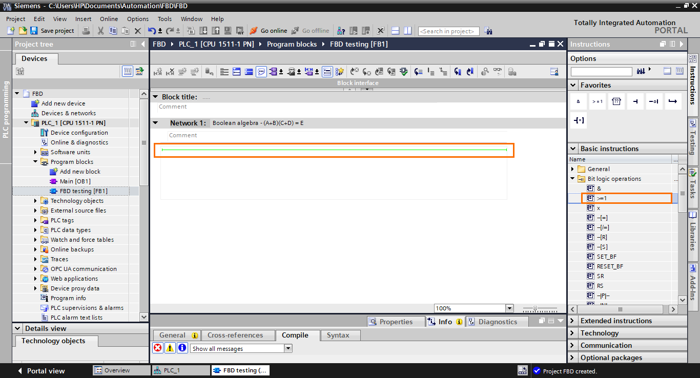
The OR function block appears in the workspace. It contains two inputs on the left, where you specify boolean tags/elements, and an output containing the logic result of the operation.
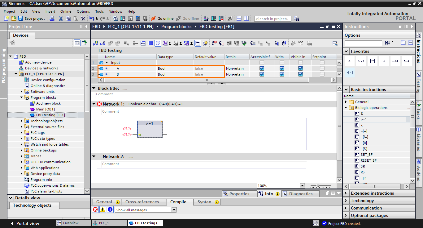
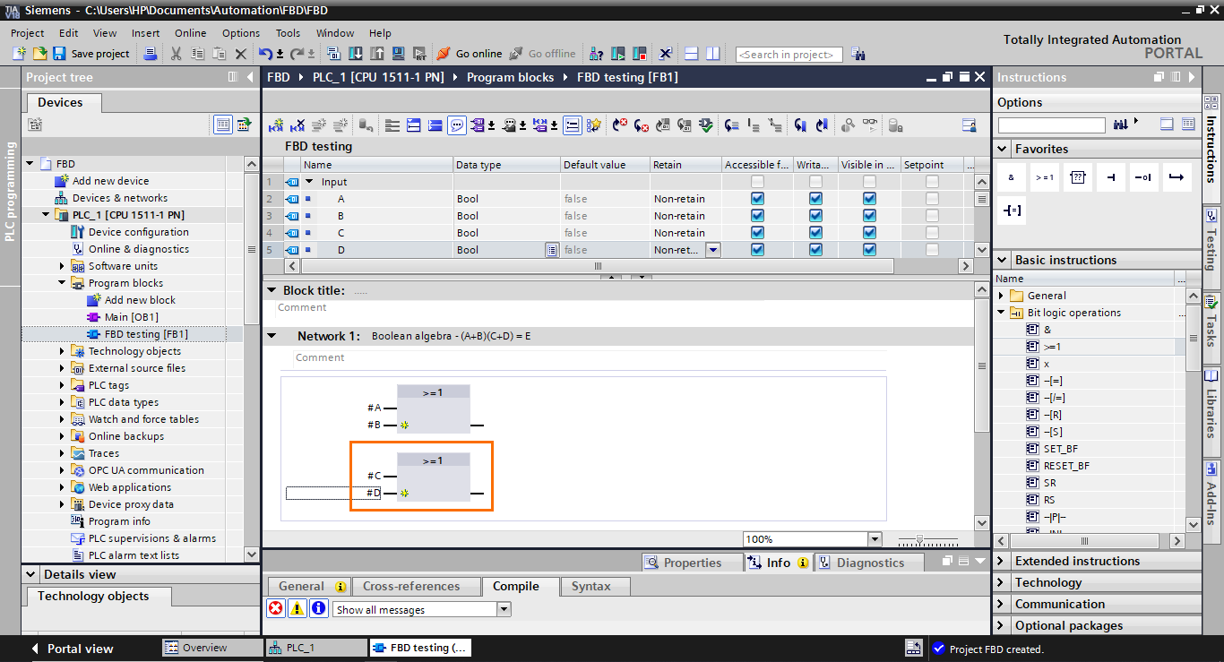
After that, create two boolean inputs in the interface (A and B) that we will use in the block to model the A + B part of the equation.
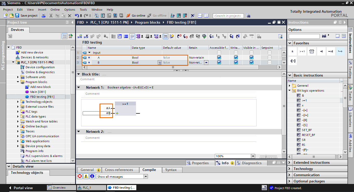
Once done, add these inputs to the block, as shown in the following figure.
Now, repeat this operation to create the C +D part. To do this, create two more Boolean inputs in the interface (C and D) and add them to a second OR function block.
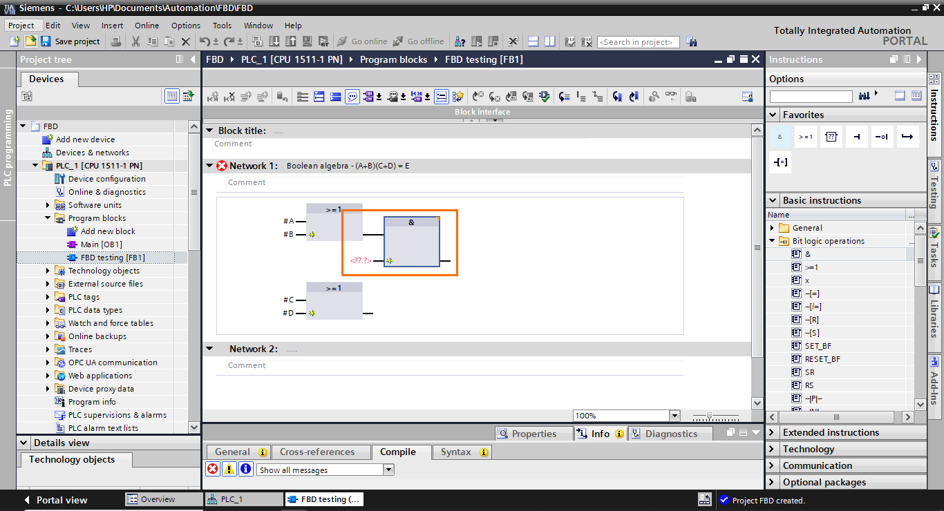
We now have the two OR parts. The next part is to connect both result outputs of these blocks to an AND function block. Select an AND operation (&) in the instructions section and drag it to the output of the first OR block.
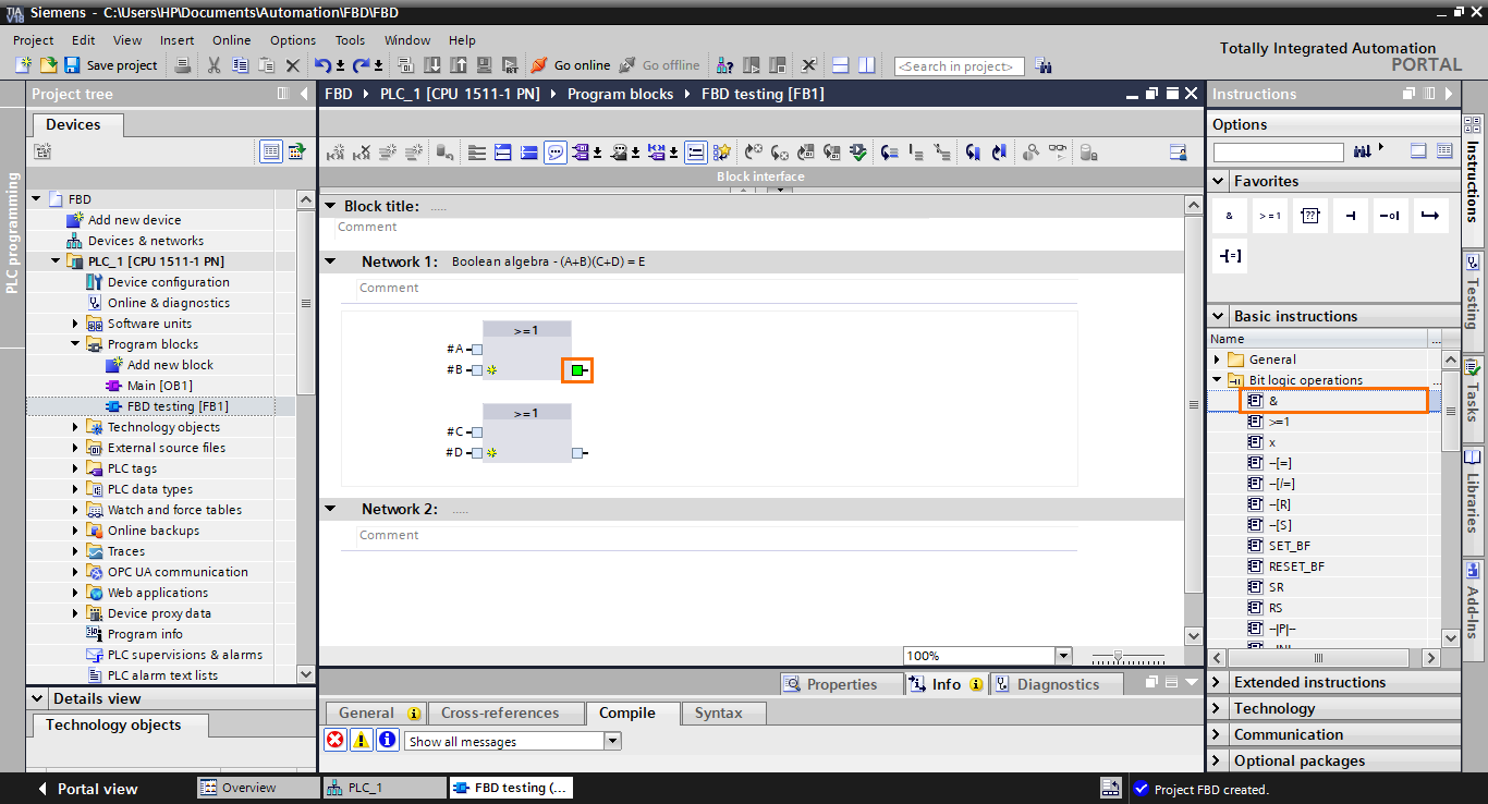
The AND block is added to the workspace with its first input connected to the output of the first OR block. However, as you can notice, it is not connected to the second OR block.
To connect the second OR block to the AND block, select its output and drag it to the second input of the AND block.
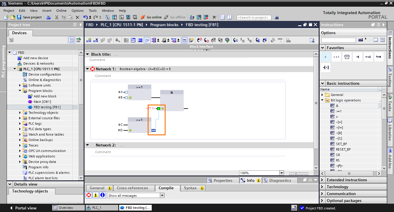
The second OR block becomes connected to the AND block.
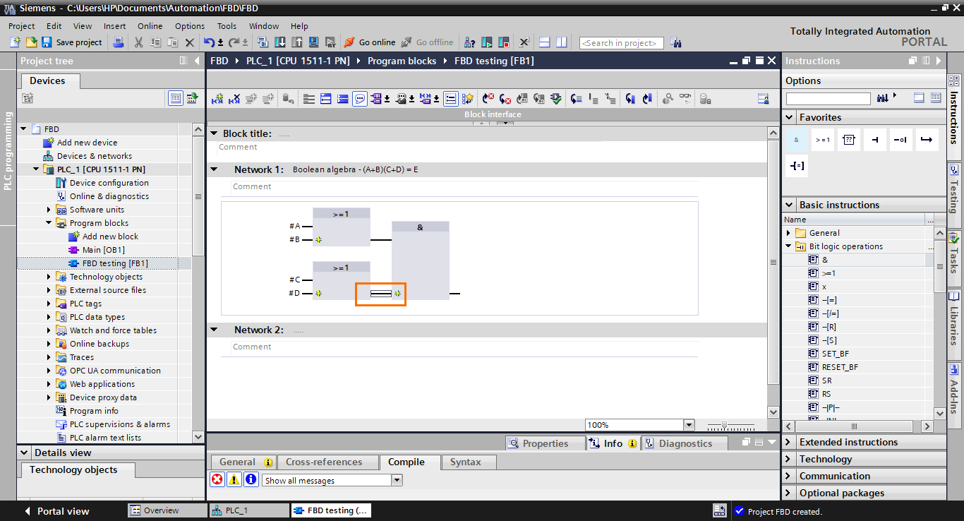
We have almost completed the construction of the equation; the last step is to retrieve the result at the output of the AND block. To do this, we have to add an affectation function block at the output of the AND block. Select the affectation function block (=) in the instructions and drag it to the AND block output.
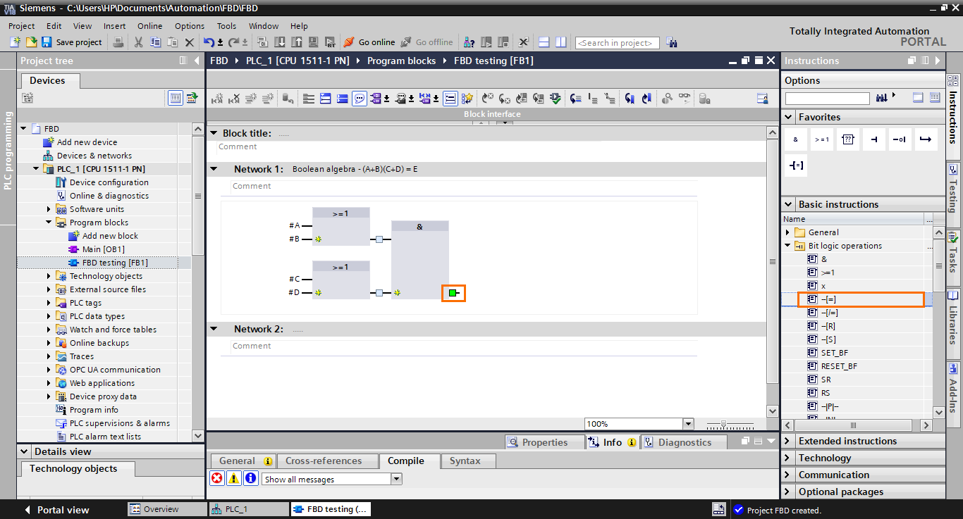
The affectation function block appears in the workspace with its input directly connected to the AND block output. It lets us retrieve a logic result and put it in a tag or interface element.
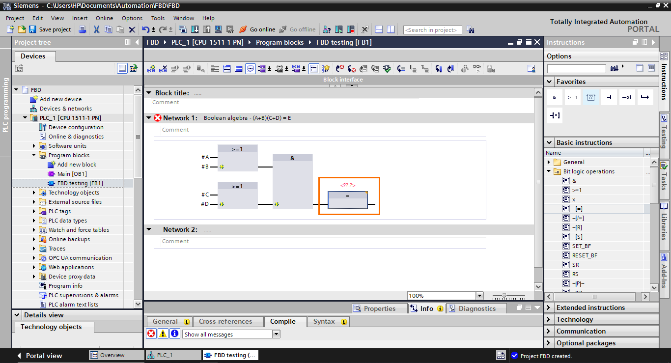
After that, create a Boolean output (E) in the blocks interface and add it to the affectation block.
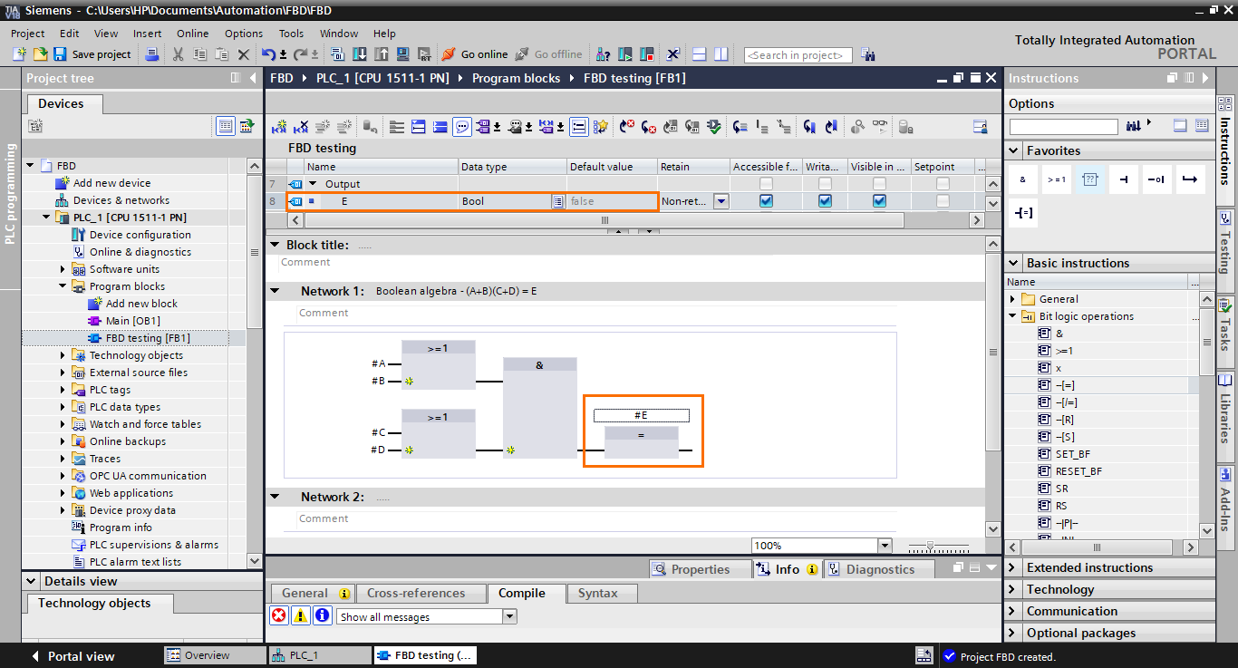
We have finished modeling the equation in FBD language.
The last thing we will cover here is how to add inputs to blocks. In cases where you need more than two inputs in a block, each block has a small yellow star icon that allows you to add multiple inputs to the block.
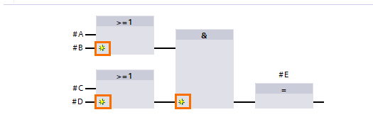
If you click on one of these icons, this will add an input to the block. Click on the yellow star icons on both OR blocks.
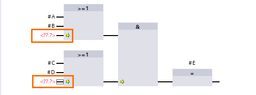
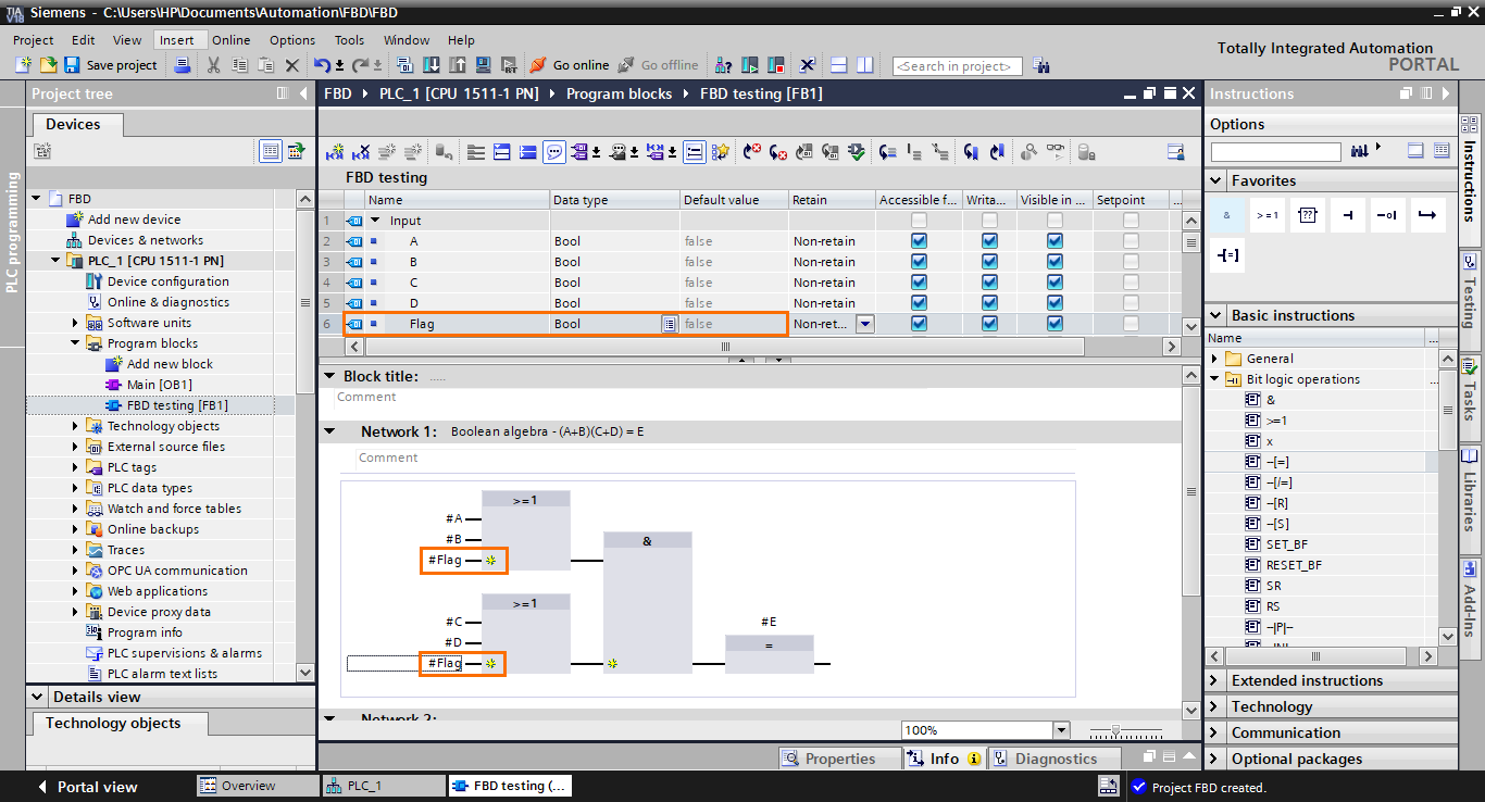
Once done, create a new Boolean input (Flag) and add it to the newly created inputs.
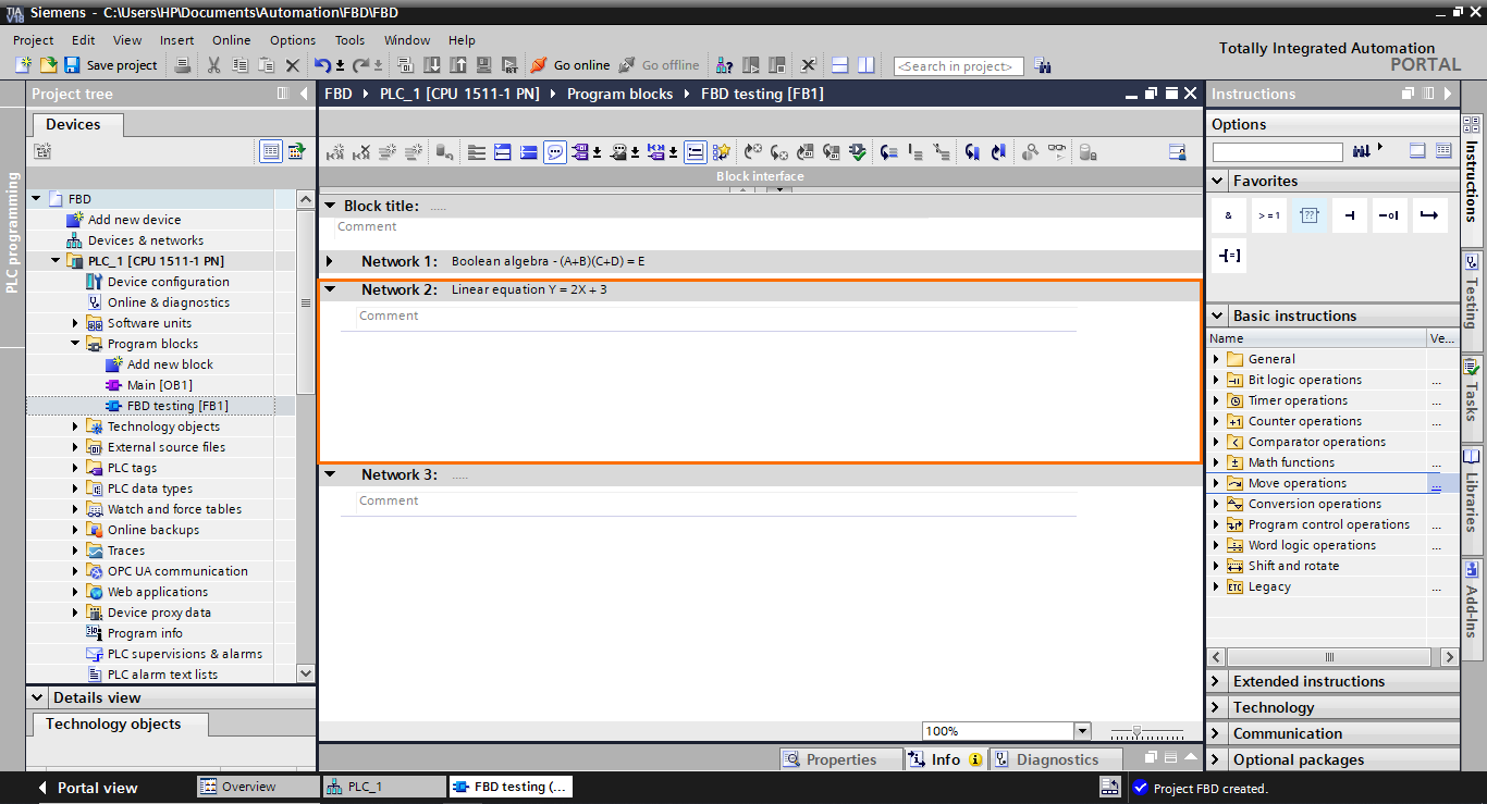
Linear equation
Let’s move on now to the linear equation. Here, we will model a simple mathematical linear equation (Y = AX + B), which consists of a multiplication followed by an addition. For this, we will use Network 2.
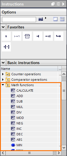
For this application, we will use Math functions. You can find them in the “Math functions” folder in the basic instructions section.
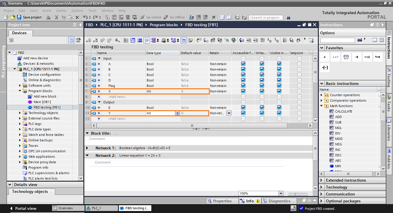
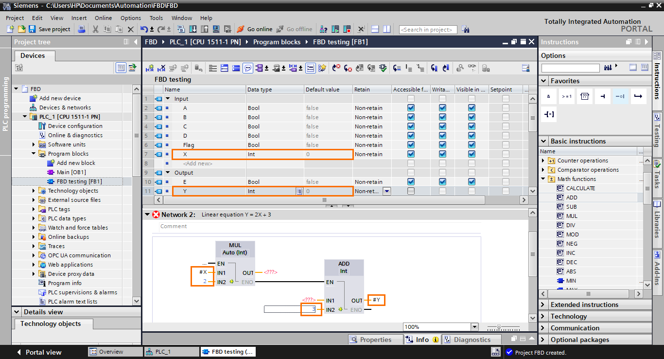
We will first start by creating two integer elements in the interface: X as an input and Y as an output.
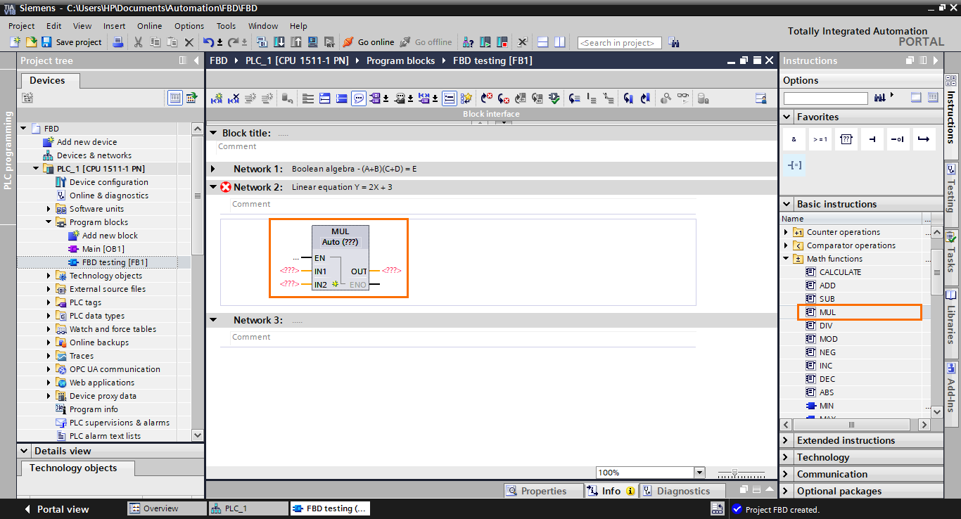
After that, add a multiplication (MUL) function block in the workspace by selecting it and dragging it.
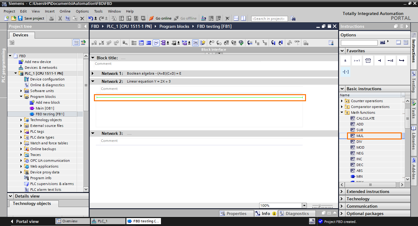
This will add a multiplication block. It has two inputs (that can be extended) for the elements to multiply and an output for the result. It also has an EN and ENO I/Os used for the block execution sequencing.
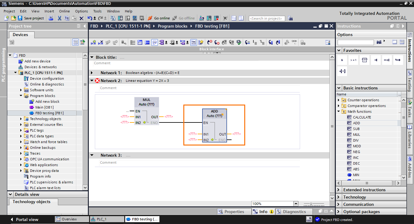
Next, we need to add a function block. Select it in the instruction list and drag it to the ENO output of the multiplication block.
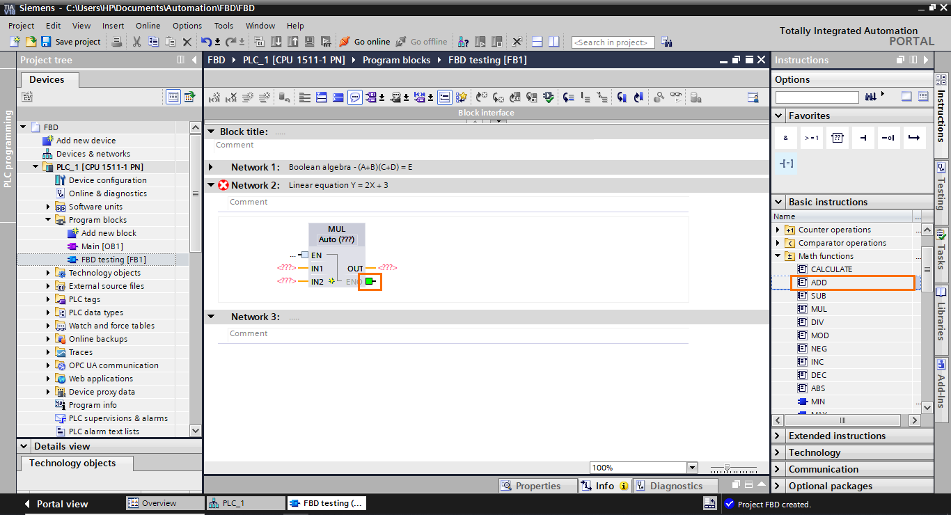
This will create an addition function block connected to the multiplication block through its EN input. As you can see, it is impossible to connect the result of the multiplication block directly to one of the inputs of the addition block. This is possible only with Boolean results.
After that, we need to add I/Os to the blocks. Fill in the blocks’ I/Os as shown in the following figure.
The last thing we need to do is to communicate the multiplication result to the input of the addition block. To do this, we will use a temporary interface element that will serve as a bridge between the blocks. Create a temp element and add it to the output of the multiplication block and the input of the addition block.
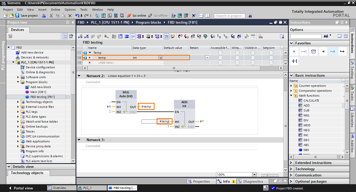
And with this, the model of the equation is done.
Motor control
For this last section, we will program a small motor control application in Network 3.
We will base ourselves on the following program in LADDER to build its equivalent in FBD.
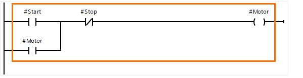
The two parallel branches (containing #Start and #Motor) translate to an OR operation. Next, the #Stop element is in series with the previous elements, translating to an AND operation. Then, the final result is affected by the #Motor element. So, to reproduce this program, we will need an OR operator, an AND operator, and an affectation.
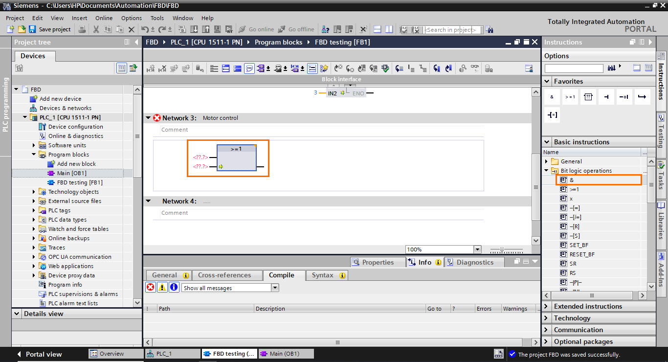
Let’s start by adding an OR block. Select it (>=1) and drag it to the workspace.
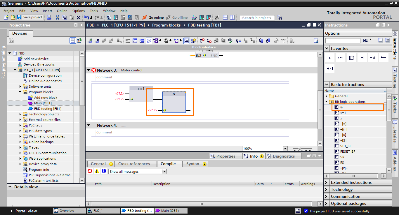
After that, repeat the same step but, this time, add an AND operator and connect it to the output of the OR block.
Since the #Stop contact is normally closed, we need to invert the second input of the AND block. Select an “invert” instruction and drag it to the second input of the AND block.
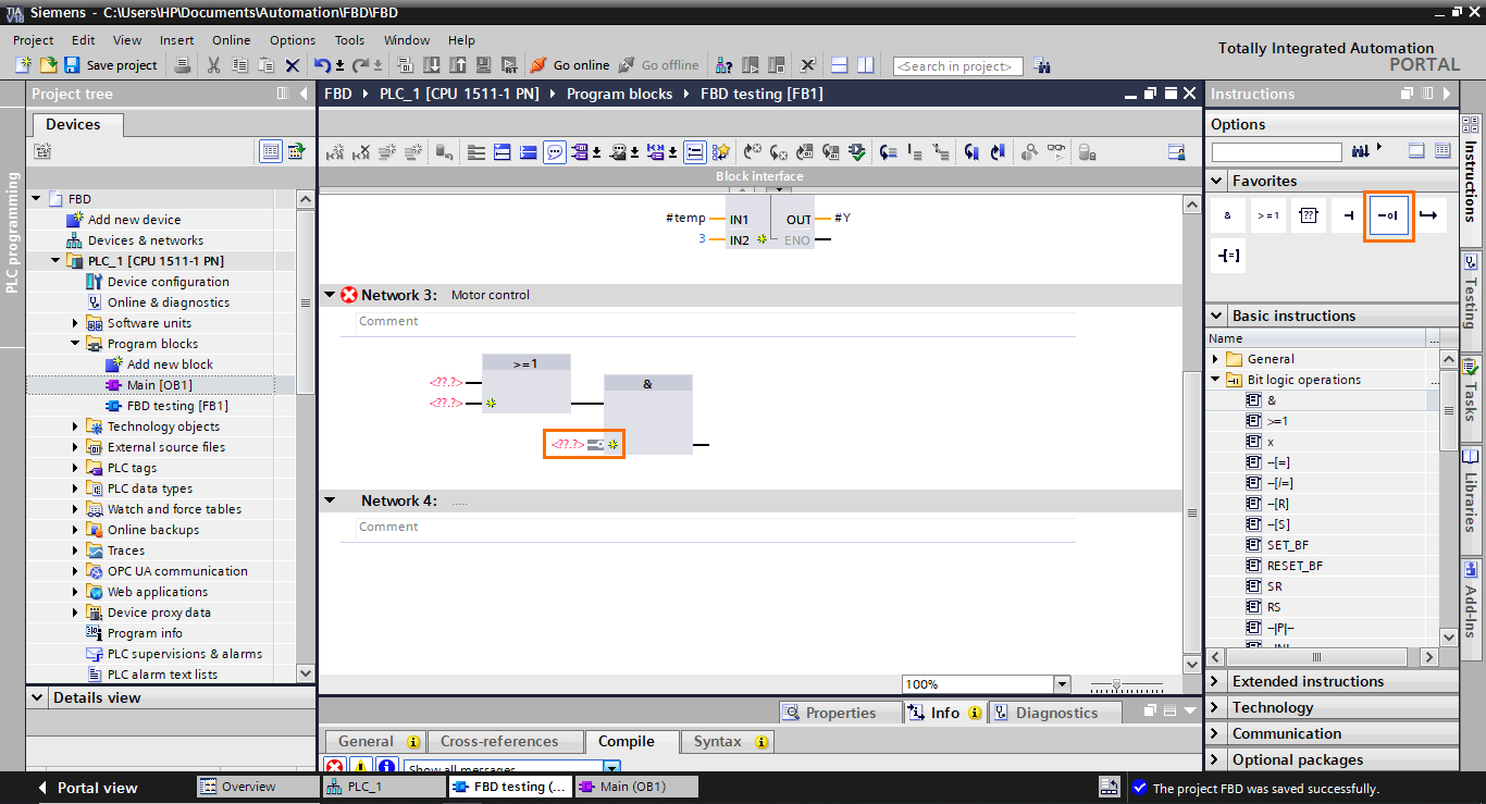
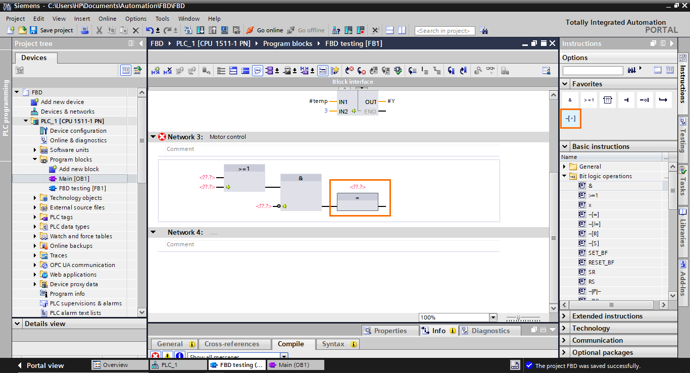
The last block we need to add is an affectation block in the output of the AND block. select it and drag it to the output of the AND block.
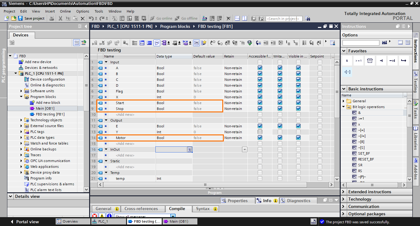
Now, you can create the I/Os we need (#Start, #Stop, and #Motor) in the interface as Booleans.
Once done, add them to the function blocks, as shown in the following figure.
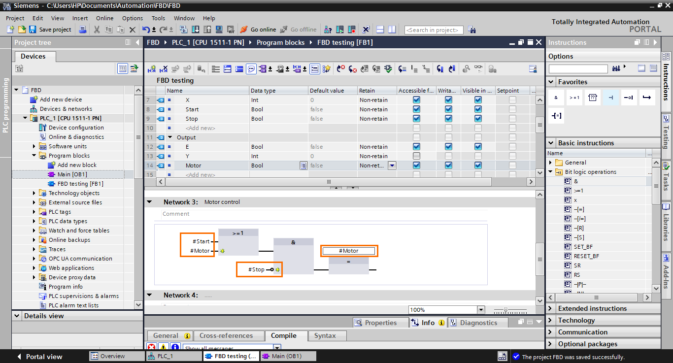
And with this, we are done with the motor control program in FBD.
Conclusion
In this tutorial, you learned how to harness the power of Siemens' Function Block Diagram (FBD) language within the TIA Portal environment. You crafted three programs with step-by-step instructions: a boolean algebra equation, a linear mathematical equation, and a motor control application. These applications cover the most common operations performed using the FBD language. Following these hands-on exercises, you gained practical experience utilizing FBD's graphical approach to design and implement control logic.
The Function Block Diagram (FBD) language is a powerful tool for creating control logic in industrial automation. FBD empowers engineers to design, debug, and maintain control systems with enhanced clarity by offering a visual means of expressing complex algorithms. Function blocks representing various operations are interconnected to model intricate control behavior, enabling seamless implementation of mathematical calculations, timing operations, and logic control. With FBD, automation engineers can bridge the gap between complex algorithms and practical implementation, fostering efficiency and accuracy in industrial automation.
