Configuring an S7-1200 PLC as DP Slave in a Fault Tolerant S7-400H System

Introduction
The establishment of communication over different CPUs is often convenient in industrial fields. However, many machines and processes must exchange operations, interlocks, and monitoring data from one controller to another. This necessity comes from determining logic decisions based on sensors, actuators, and logic states located in different process sectors and areas.
There are some ways to implement data exchange between PLCs. However, to determine the best-suited communication structure for your automation project, you should be aware of the physical environment, communication protocol, and hardware aspects.
Physical Environment
To choose the physical environment, it’s crucial to determine the type of communication. Typically, it’s established as a wired interface. Depending on the protocol utilized, a wired interface could be hard-wired(commonly dry contact over 24 V) or a more complex signal tied to specific communication cables. The cables are specified according to physical needs to offer proper maintenance survivability.
Communication Protocol
Industrial communication protocols come with many data insurance and equipment compatibility. Therefore, choosing industrial protocols that fit your project's needs regarding communication speed, system recovery, data insurance, and compatibility with all equipment is very important. These are all standard industrial communication protocols for Profibus, Profinet, DeviceNet, Ethernet/IP, ControlNet, EtherCat, and AS-I.
Hardware
Not only do the cable and processors need to be compatible with the communication interface, but the way controllers recognize these data varies from protocol to protocol. This way, it’s often necessary to acquire communication adapters (and/or modules) to make your CPU recognize the other CPU’s messages. Between Siemens’ CPUs, for instance, you should be able to communicate via Profibus/DP with no additional costs if both pieces of equipment have Profibus/DP ports available. In newer Siemens’ CPUs, however, Profibus/DP ports are not as popular as they used to be, meaning a Profibus/DP Communication Module (CM) should be installed. Alternatively, a Profinet CP could be added to the older CPU to settle communication over Profinet Interface.
Case Study
In this tutorial, we’ll cover the steps to configure a Master-Slave communication over Profibus/DP protocol, composed of an S7-400H Fault Tolerant CPUs (master) and an S7-1200 1214c (Slave). The Slave CPU acts as a network I/O device in this project to provide the master CPU with cyclical process data. This scenario is commonly used when treating the slave CPU merely as a Remote I/O component, where all the dynamics tied to communication establishment parameters and continuity are tied to the Profibus/DP protocol and the remote I/O OB image structure processing from Siemens. An alternative to this approach would be to implement this message exchange with MPI's XGET/XPUT to mirror whole DBs between the CPUs or even programming a Modbus/OPC communication routine.
In this tutorial, we'll utilize the following hardware & software:
- Siemens TIA Portal v16 + CPU S7-1200 1214c + CM1242-5 DP Slave CM
- Simatic manager v5.6 + S7-400H rack + IM 153 Y-Coupler
Configuration in Siemens TIA Portal
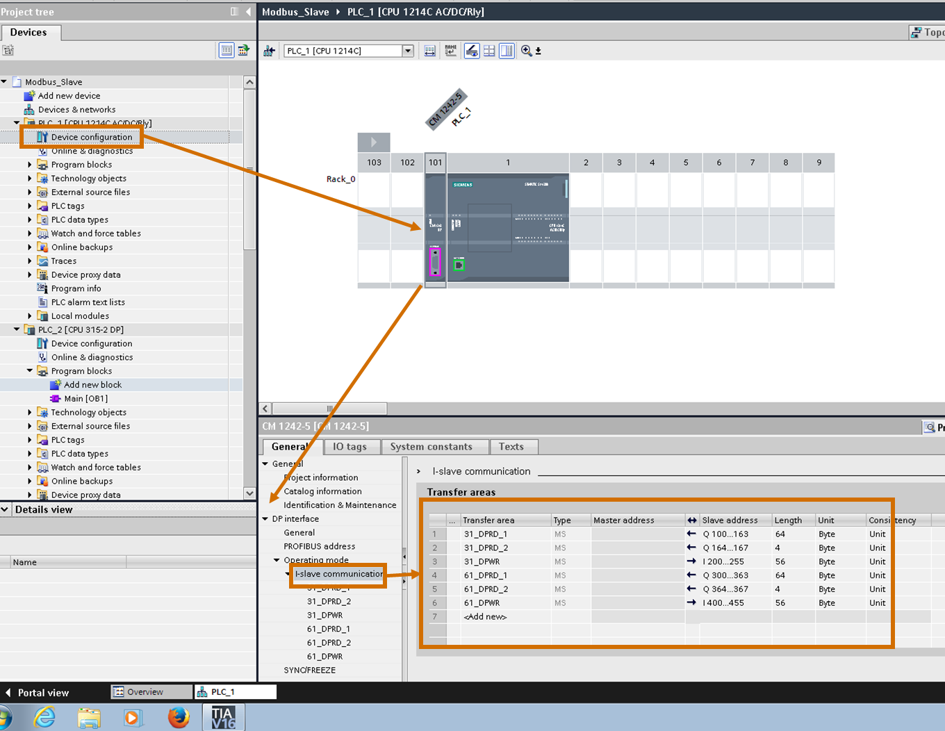
First, add the correct CPU and CM to the TIA Portal device configuration. Then, under the communication module's properties, find the I/O mapping area. In this field, it's possible to add Input and Output areas of memory to be exchanged with the Master CPU. Remember that the arrow pointing right means an Input to the slave CPU (Output from S7-400), and an arrow pointing left indicates an output to the Master CPU (Input for S7-400).
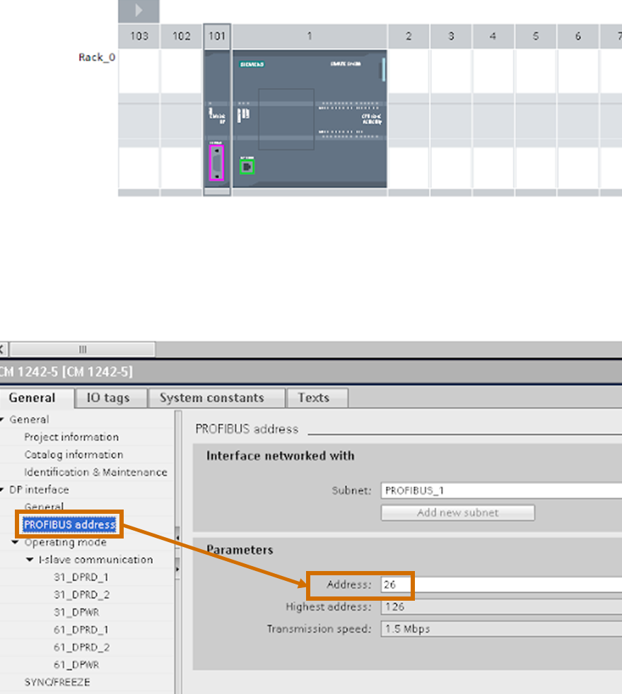
It's necessary to assign a Profibus Address to the communication module. This Address is an integer number ranging from 1 to 127(depending on the network structure) and is an identifier for all devices in the Profibus network. This same Address should be configured in the Simatic Manager hardware configuration when adding the remote I/O device.
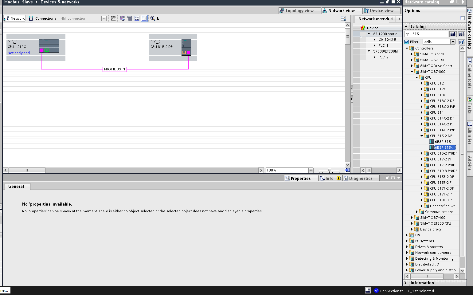
To ease the network operation monitoring and project structure (when the Master device is also programmed in the same TIA Project), it's also feasible to add the Master CPU in the project and configure the communication topology in the network & devices screen. This step is not mandatory.
Cyclic I/O Data Exchange in TIA Portal
There are two ways to read and write the memory areas from the Profibus/DP interface. The quicker one consists of the direct assignment of tags within the I/O configured in the CM. We're automatically reading and writing to those data in every routine Cycle by utilizing these tags in the code. A move instruction, for instance, in Ladder Logic, can be used to read or write to ID200 / QD200 ( Input / Output DWord 200). The syntax is as follows:
- Digital input - I100.0 (First bit of the byte 100)
- Digital Output - Q201.2 (Third bit of the byte 201)
- Byte Input - IB152 (Byte 152)
- Word Output - QW364 (Word starting at 364.0 to 365.7)
- Double Word Input - QD300 (Double Word starting at 300.0 to 303.7)
Be aware that the memory type index merely refers to how many bits are being used and they all share the same memory area. I100.2 is a bit inside of the word IW100, and trying to configure both tags might result in conflicts.
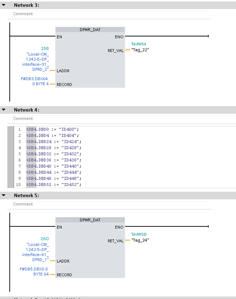
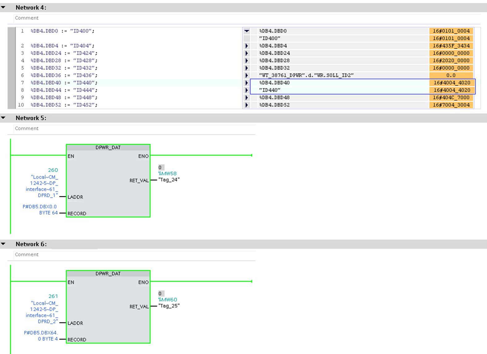
In this example below, we're reading Double Words and mapping to a mirroring DB on the first network utilizing SCL. Compared to ladder logic, this approach is an easy way to perform multiple move operations.
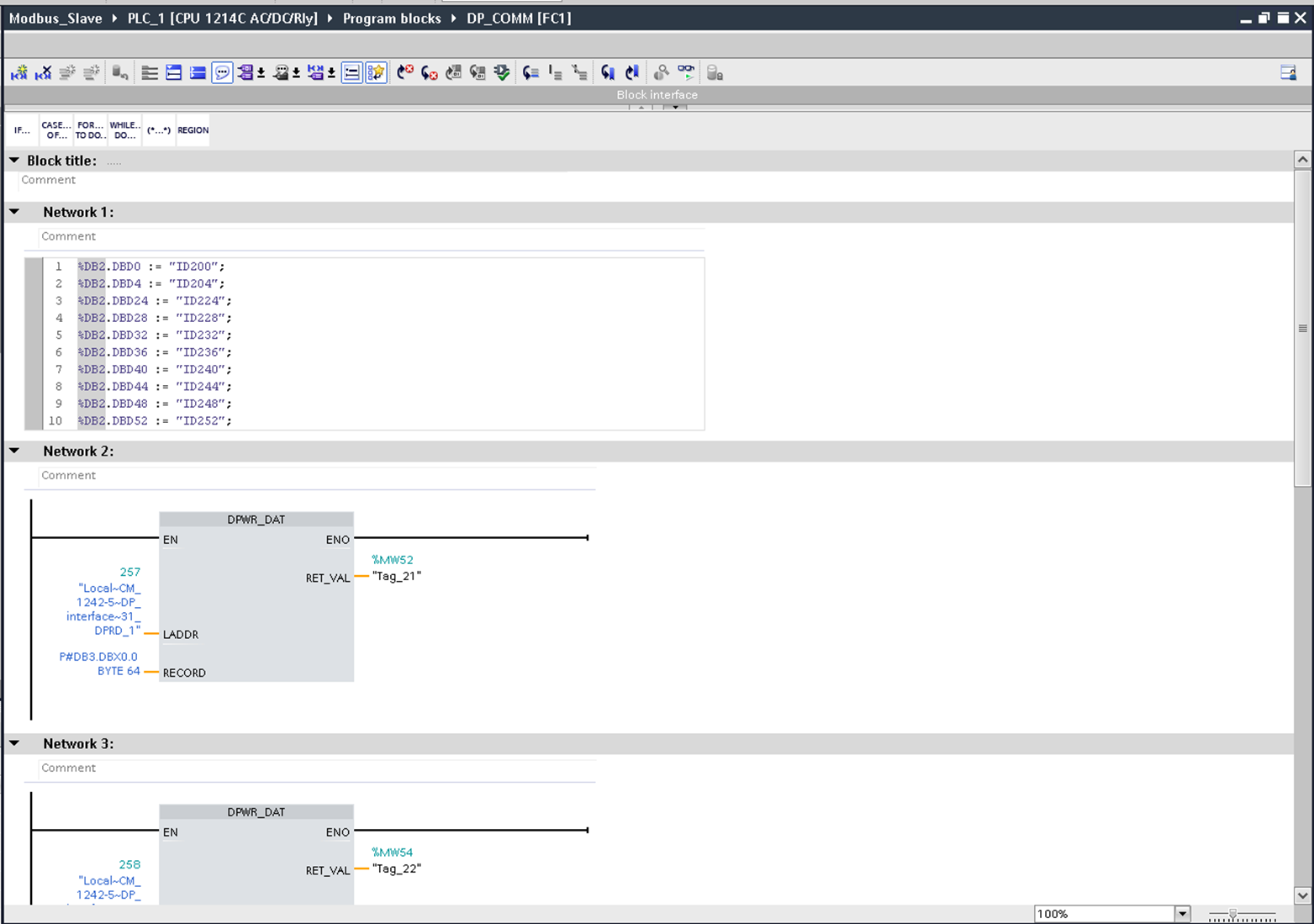
Another way to perform the cyclic read and write task for higher amounts of data is to utilize the DPWR_DAT and DPRD_DAT blocks. These blocks are present in Siemens’ open library to facilitate the DP data transmission. The following block inputs and Output are configurable:
LADDR - this is the memory area address to be read/write in hexadecimal. I100 would be a DPRead from LADDR 16#64, for example.
RECORD - data location to map the input information(DPRead) or to pass the values to be written in outputs(DPWrite). This parameter accepts absolute, symbolic tags (DBX.DBWY / "DB name"."Tagname") or even as many bytes as you want from the starting address defined with (DBX.DBY.0 BYTE N, where N is the number of Bytes).
Retval - a word that indicates the block status, helpful in monitoring error codes when the communication is malfunctioning.
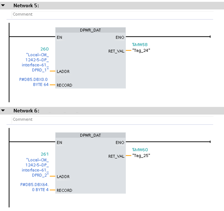
In this project, the following data exchange was also configured:
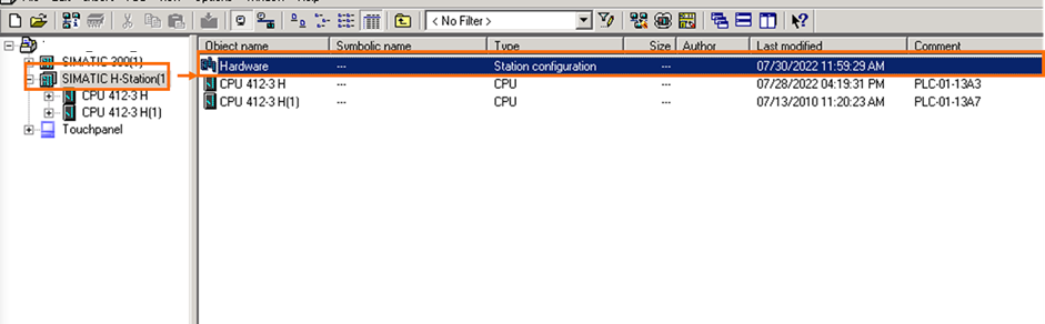
Configuring Siemens Simatic Manager
In the existing S7-400H program, we need to add the Remote Profibus DP I/O device. To do so, let’s step into our Station’s Hardware Configuration.
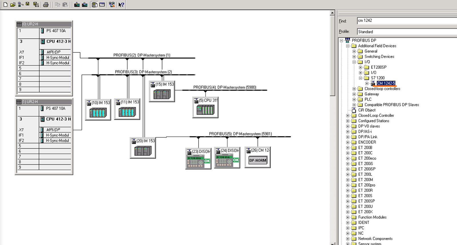
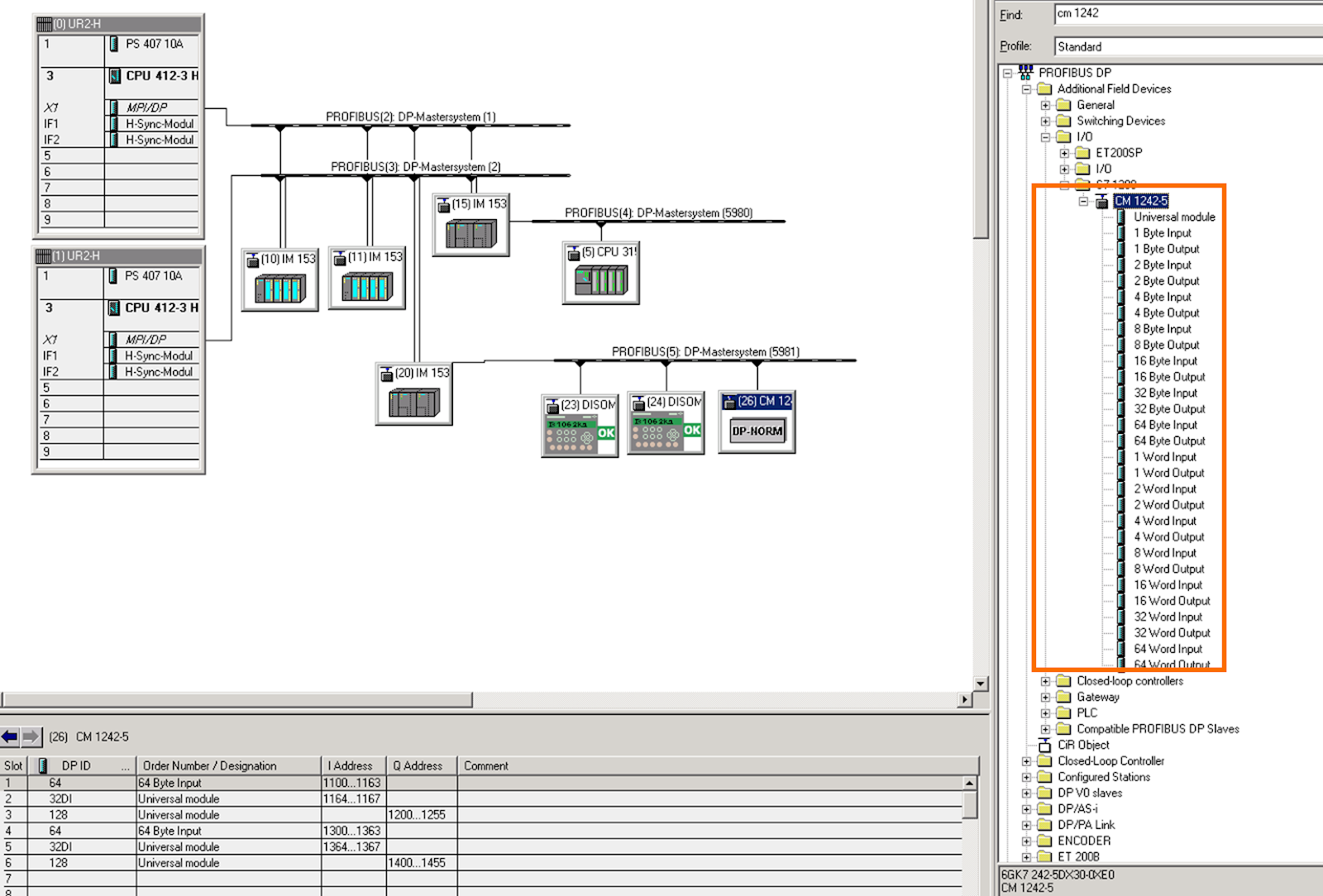
In the hardware catalog list, on the right panel of the HW Config tool, find the Profibus GSD File corresponding to the Profibus Slave (in this case, our Profibus Slave Module CM 1242-5).
OBS: If you don’t have the hardware configuration file (GSD), download it from the vendor’s website (in this case, Siemens) and proceed to install it when in HW Config tool, at “Options” and “Install GSD File”. This procedure is quite simple, you just need to follow the wizard. Every Profibus I/O device needs its GSD file to discriminate its data structure to the siemens PLC.
Select the Profibus Interface you wish to add to the Profibus Slave and double-click the module in the catalog list to add it to the network. In our case, we’re adding the module at the Profibus branch after the IM 153(Y coupler), since we want the device to communicate to whatever PLC is currently running the user program in the redundant system. As its name may suggest, the Y Coupler module offers an option to compose two redundant Profibus networks into a single Profibus output branch.
Expand the hardware catalog's CM 1242-5 GSD to find its I/O modules. These I/O modules are configurable Input and Output memory areas, similar to what we have already configured in TIA Portal for the CM 1242-5 Slave. You can add either the predefined I/O modules (e.g. 1 Byte Input) or choose universal modules to fit any Input/Output range to a max of 64 bytes.
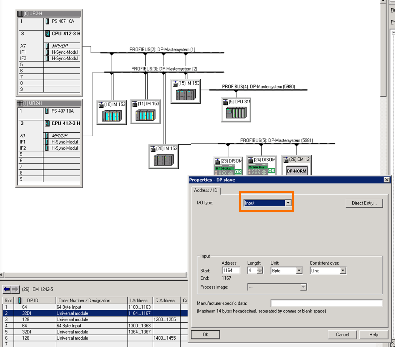
Configure the I/O type according to Input/Output data when adding the universal modules. Be aware that the whole I/O mapping should be equivalent to what's mapped in the TIA Portal program, considering that Inputs in the Master side (Simatic Manager) are outputs in the Slave side (TIA Portal) and vice versa.
Next, we need to configure the device's Profibus address. Right-click the CM 1242-5 module to open the "Object Properties" window.
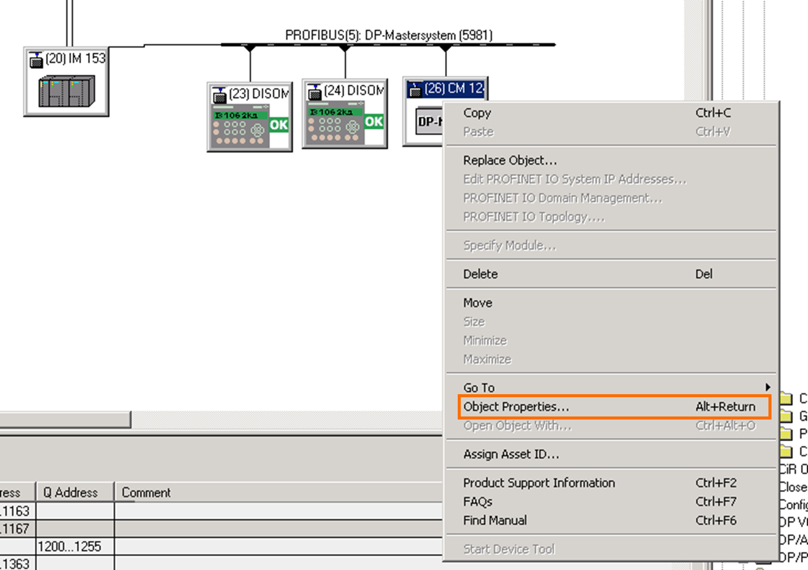
Click on the configured Profibus network to open the PROFIBUS interface configuration utility and change the device's Profibus Address according to the address set in TIA Portal.
OBS: since this configuration carries hardware settings in TIA Portal and Simatic Manager, hardware downloads are mandatory. Be aware that a hardware download always takes the CPU to a STOP state during the download.

Cyclic I/O Data Exchange in Simatic Manager
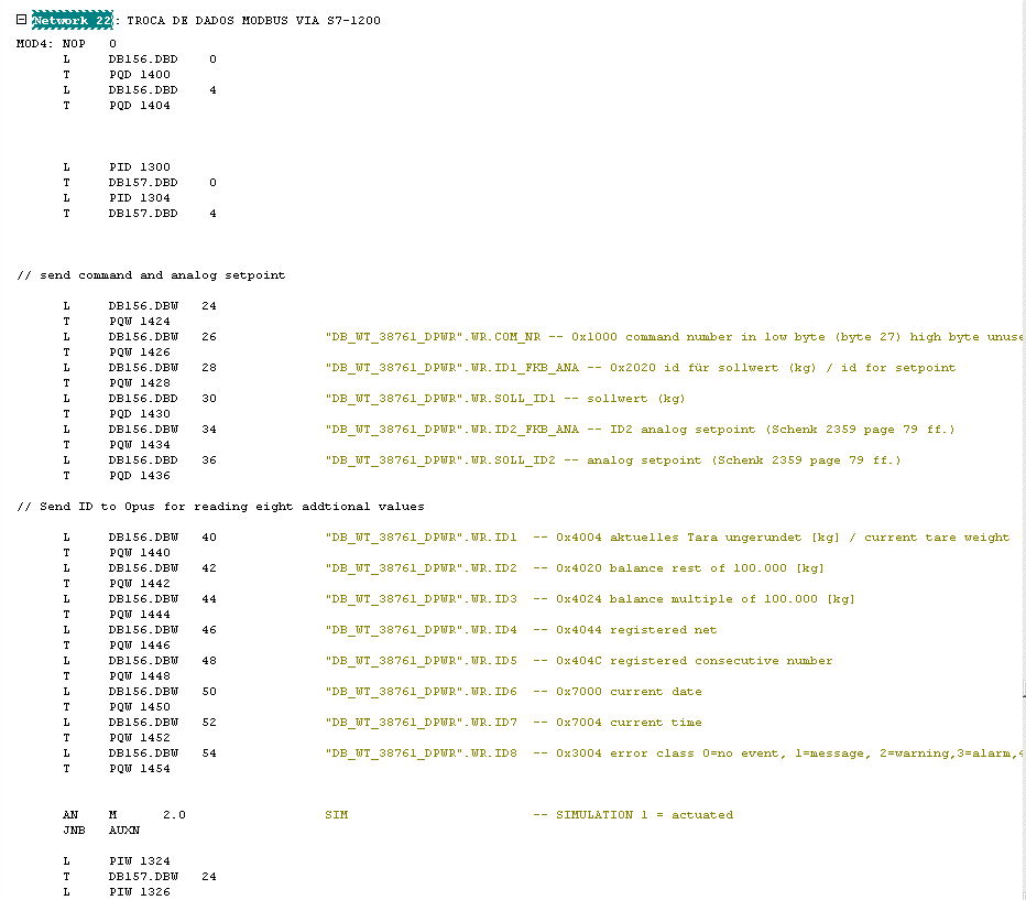
The image below shows a traditional way of reading and writing data from peripheral inputs in Simatic Manager's STL language. The equivalent methods described before (SCL and Ladder Logic covered in TIA Portal) are also available.
Testing the Communication
After downloading the user programs to both CPUs, observe, at the SCL network, the mapping of each value in real time for the individual tags. The DPWR blocks are also functioning correctly as we're receiving "0", meaning no errors, at the RETVAL.
Conclusion
Setting up communication interfaces between different CPUs might be a challenging task. However, we've confirmed the usefulness of utilizing the Profibus/DP protocol to ensure cyclical data exchange; by choosing this method, it's possible to take advantage of the protocol's structure (which makes us benefit from its communication speed, data insurance, and system recovery algorithms).
These communication methods are fundamental in plants where control elements are distributed across multiple PLCs. Setting up data exchange between specific machines to a central Supervisory/Scada concentrator PLC is common. Besides sharing diagnostics and monitoring information, exchanging process conditions and interlocks is feasible when establishing industrial data communication.
A downside to this approach is that it requires hardware download to both CPUs, meaning both controllers needs to go to the STOP state for the procedure; this can lead to undesirable productivity downtime.
