Getting Started with Simulating Circuit Programs in Siemens LOGO! Soft Comfort

Introduction
Mastering the simulation process in Siemens LOGO! PLC can provide several benefits.
First, it allows for error detection in the control circuit program before it is implemented in real-life situations. Second, you can identify design flaws and adjust parameters to improve the circuit's performance and safety.
Third, it allows for the testing of the circuit program without the need for actual hardware, which can save time and resources. Fourth, you gain an understanding of how the program works, how it interacts with various inputs, and how it produces outputs.
Fifth, it provides a more accurate representation of the circuit's behavior than physical testing. Why? Because physical testing can be affected by external factors. Sixth, it allows for testing different scenarios without physical changes to the control circuit. Thus, it provides greater flexibility in experimentation.
And seventh, it helps to identify potential risks and hazards associated with the circuit program. It allows us to make changes before the circuit is implemented, reducing the risk of errors and accidents.
Prerequisites
What you will need to follow along with this tutorial:
- Ensure the LOGO! Soft Comfort software is installed and running correctly on your computer. Although the tutorial mentions version 8.3, you can use other software versions too.
- You must be familiar with project creation tools and functions in LOGO! Soft Comfort.
Initiating the Simulation Process
There are two ways to place your circuit program in simulation mode. First, you can use the simulation icon available in the programming toolbar. Second, navigate to the "Tools" menu in the top toolbar and select "Simulation."
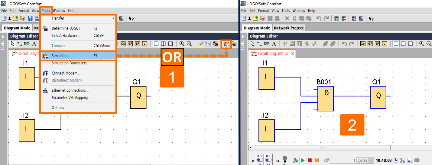
When you begin the simulation, LOGO! Soft Comfort conducts a circuit program check to detect and report errors, shown in the "Info Window." You can access the "Info Window" by selecting "View → Info Window" from the menu bar or hitting the function key [F4].

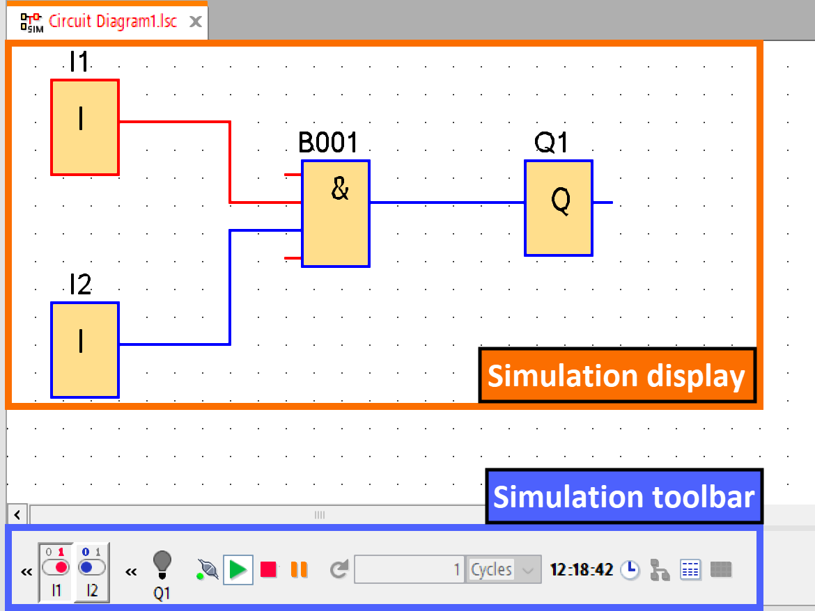
When your circuit program is in simulation mode, you are provided with the simulation toolbar and the status window. These tools will enable you to simulate your program and monitor and control its behavior.
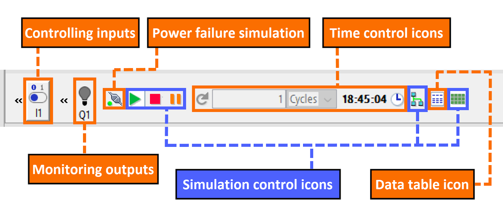
Within the simulation toolbar, you can access an array of icons, each with unique functions, which include the following:
- Icons, like switches, are provided for users to control the inputs.
- The power failure simulation icon. It allows testing the switching response concerning retentivity characteristics following a power failure.
- Icons, like bulbs, are provided for users to monitor the outputs.
- Control icons for regulating the simulation process.
- Control icons for time management.
- Data table management icon.
By clicking on the << button, you can make a particular part of the toolbar disappear. If you want to bring it back, you need to click on the >> button.

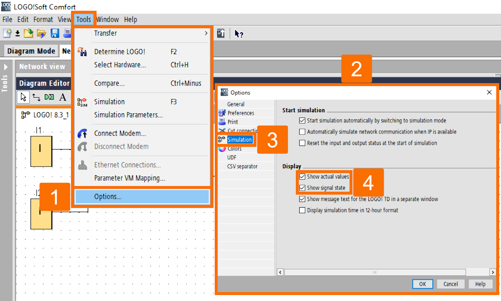
If you want to view the status of signals and process variables, you can activate them using the Tools → Options: Simulation command.
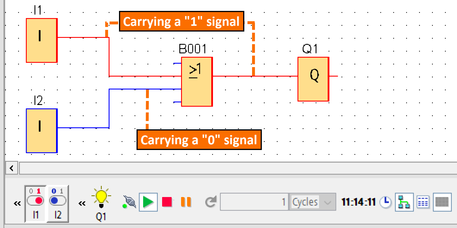
By default, the connecting lines in the display are indicated in either red or blue to indicate whether they are carrying a "1" or a "0" signal. This colored sign helps to distinguish between the two statuses ("1" or "0") of connecting lines.
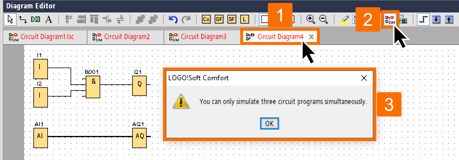
The software allows for the simultaneous simulation of up to three circuit programs. A warning dialog will appear if a user tries to simulate a fourth.
Inputs Layout
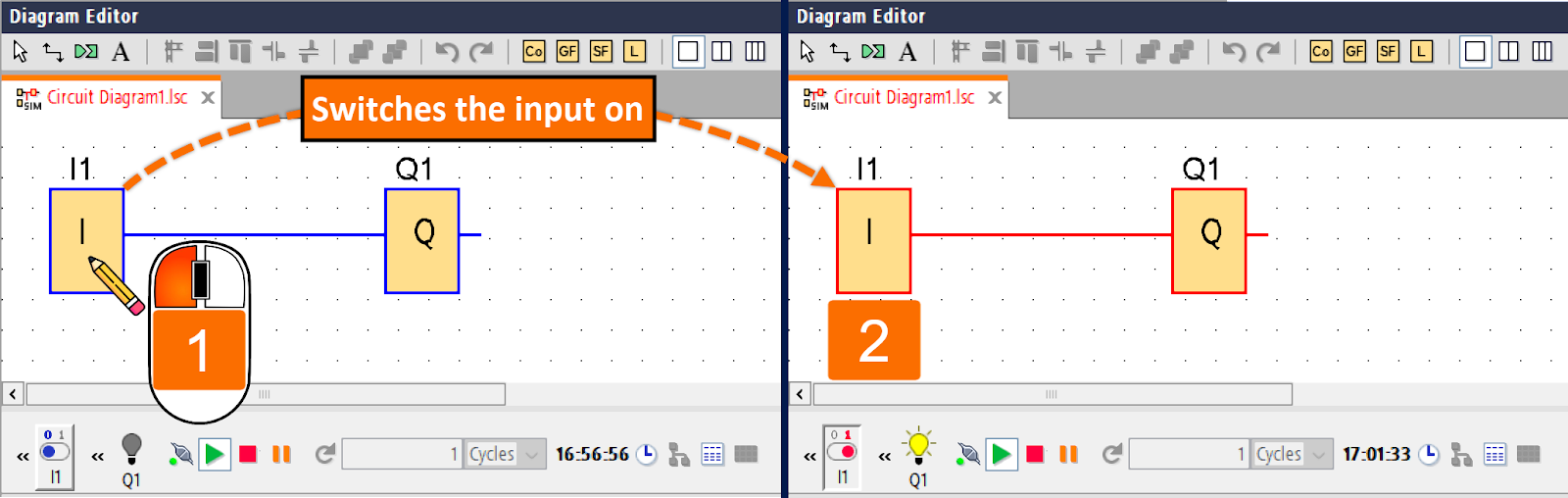
Inputs within LOGO Soft Comfort are represented by icons resembling keys or switches. Also, their corresponding names will be displayed below the icons. When an input is open in LOGO Soft Comfort, it is represented as a deactivated switch with a blue color. Upon clicking the icon, the switch turns on and is indicated by a red color.

If you need to set the values for analog and frequency inputs, one option is to use a sliding resistor to adjust the analog voltage or frequency. To do so, click on the corresponding block in the diagram to access the sliding resistor and operate it directly.
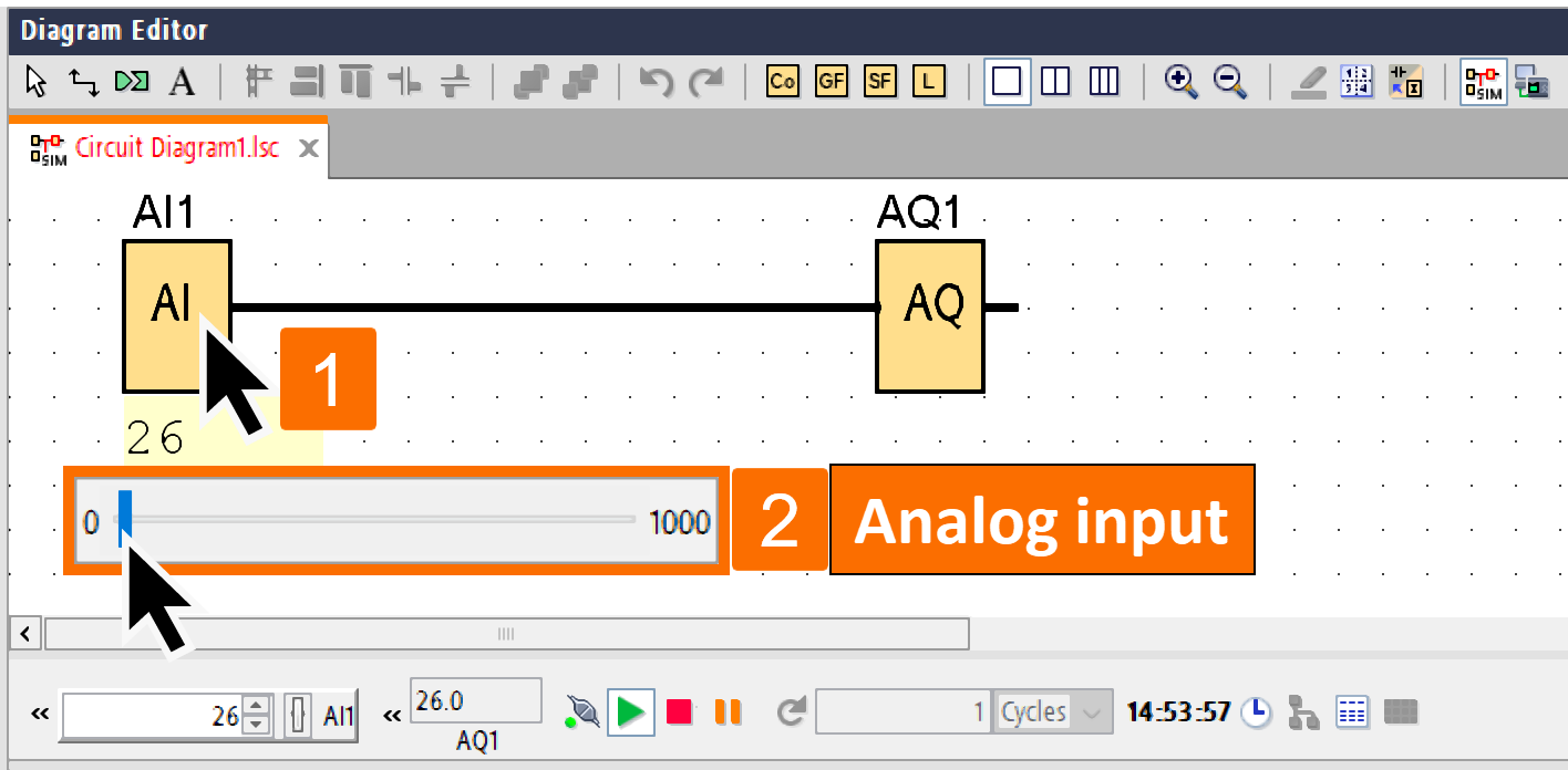
To input a more accurate value, you can either directly enter it or use the up/down keys located next to the input window to set it.
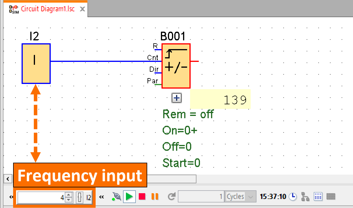
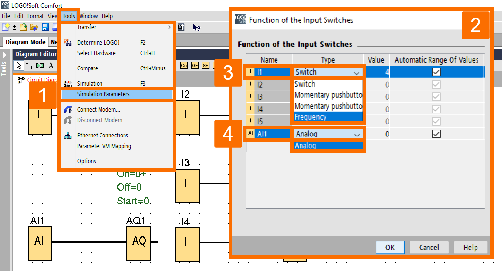
You can specify your input response for simulation purposes. To achieve this, navigate to the top toolbar to click "Tools," then select "Simulation Parameters." The dialog box displays only the inputs utilized currently within the circuit program. Your digital inputs can be configured in one of four ways. These options are "Switch," "Momentary pushbutton (make)," "Momentary pushbutton (break)," or "Frequency." Your choices are limited when analog inputs come into play, as you have only one option: "Analog."
Outputs Layout
Once you are in simulation mode, Logo Soft Comfort will display the flags M and outputs Q as the designated output options. The output's or flag's status can be discerned with ease in LOGO Soft Comfort. It is achieved through light and dark bulb icons. An off bulb indicates the switched-off output or flag, and a bright bulb represents the switched-on output or flag. The output name within the circuit program will be displayed beneath the bulb icon in Logo Soft Comfort. It aids users in rapid identification. The bulb icon in the software serves only as a visual representation of the output's status and is not a clickable switch for turning the output on or off.

Set Output
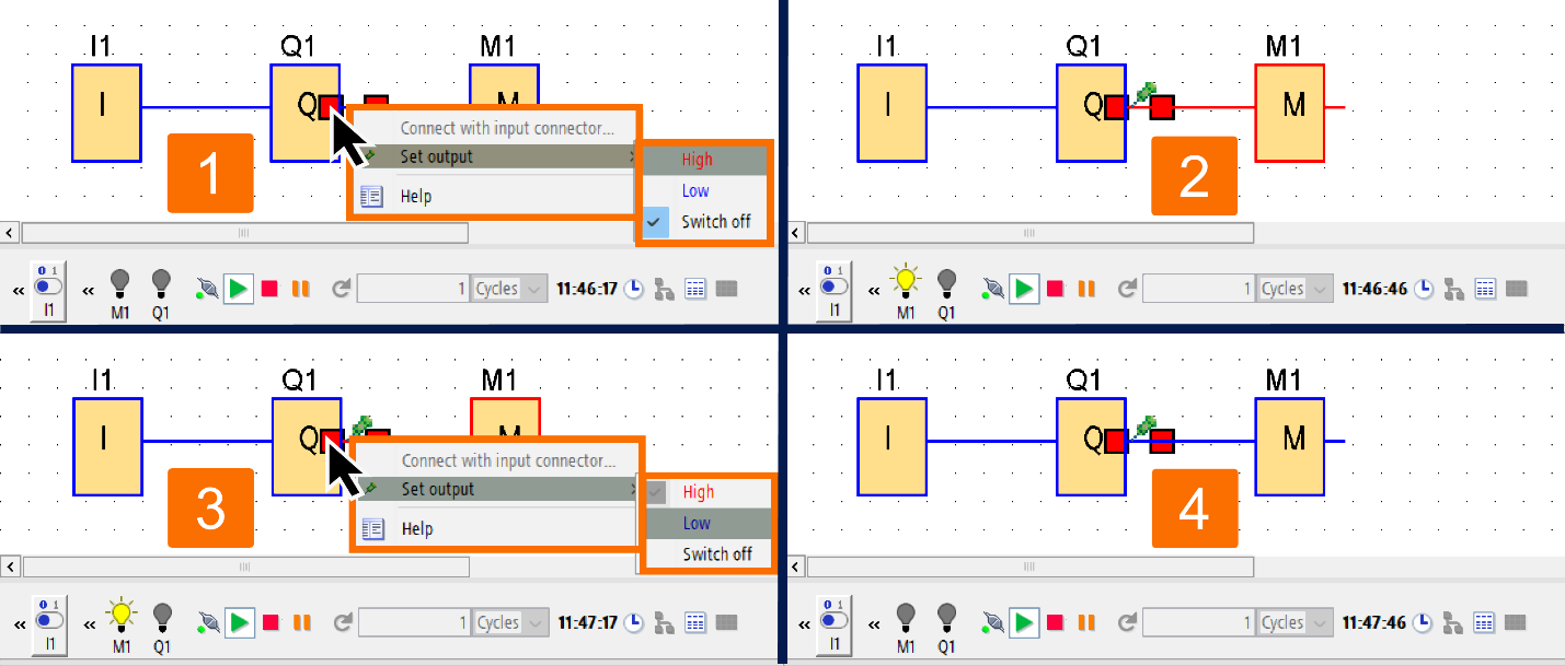
When operating in simulation mode, the block output can be set by using a right-click on the digital output pin of the block. If you use this command, you can configure the output, regardless of the current situation of the block, without any restrictions. Once set, the output will stay in that state until you re-enable it or stop the simulation. As a result, you can evaluate how a circuit program will react to specific states, thereby providing valuable insights.
Power disruption
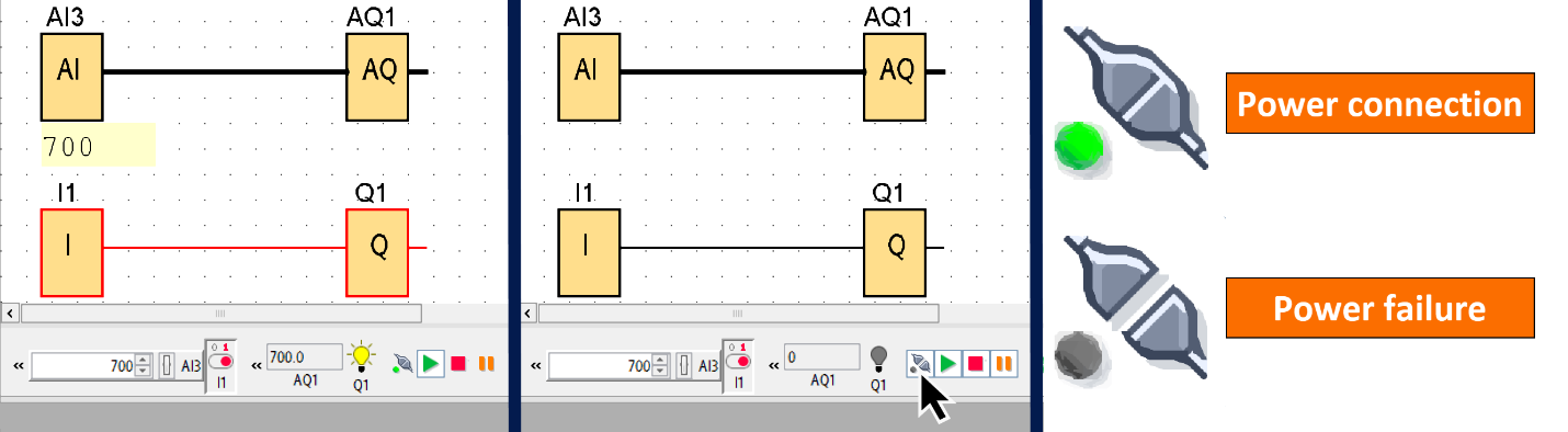
By pressing and holding the power icon, the user can simulate a power failure that interrupts the power supply to all inputs. This way, you can emulate the effects of an actual power outage. By utilizing this function, you can assess the circuit's behavior when a power outage and power restoration occurs. In addition, you can evaluate the retention capabilities of your circuit program. While retentivity is not a concern at the start of the simulation, it becomes crucial when utilizing the power failure function. LOGO Soft Comfort treats the commencement of a simulation as if the Load Program function has been activated. It results in the reset of all values, including the retentive ones.
Parameter Configuration during the Simulation Process
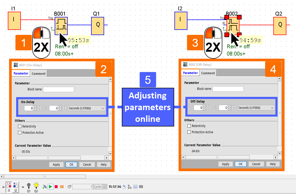
While the simulation mode is active, you can open the block properties dialog by double-clicking on the relevant block. Here, similar to the programming mode, you can edit comments and parameters in this context. Doing so allows you to fine-tune your settings and make any necessary modifications. When the software is in simulation mode, you can observe the parameter values in real-time. It can be used as an analysis technique to assess the functionality of your circuit program. In simulation mode, you can open multiple parameter assignment windows simultaneously. This way, you can make several adjustments to the circuit program together, streamlining the process.
Alternative Approach
You can activate or deactivate the inputs by directly clicking on them by entering simulation mode. It provides an efficient and straightforward means of controlling the circuit program.
Conclusion
In conclusion, you learned two ways to initiate the simulation process. You can use the Tools → Simulation menu command in the top toolbar or the simulation icon in the programming toolbar. You learned where to check detected errors when the simulation started. You got familiar with the simulation toolbar and its array of icons, each with unique functions. You understood the simulation status display and how to distinguish between the two statuses ("1" or "0") of connecting lines. You learned to control digital and analog inputs using switch icons and sliding resistors.
You got acquainted with the display of flags and outputs in the simulation mode. You understood how to configure the output, regardless of the current situation of the block, without any restrictions. You learned to emulate the effects of an actual power outage that interrupts the power supply to all inputs. Finally, you learned how to configure block parameters right in the middle of the simulation process.
In essence, mastering the simulation process in Siemens Logo PLC can provide benefits that can save time, money, and effort. At the same time, it results in improving the performance, efficiency, and safety of the circuit program within the software.
