How to Create HMI Animations and Events in Siemens TIA Portal

Introduction
Animations are used to visually represent processes and their current states. In this tutorial, you will learn how to create HMI animations & event in Siemens TIA Portal by building a simple batch mixing process.
Along the way, you will learn how to :
- Add buttons and other elements such as pipes, motors from the TIA Portal symbol library to your HMI screen.
- Configure the click and touch actions.
- Change the appearance of different elements.
Prerequisites
To follow along this tutorial, you’ll need an installation of TIA Portal. In this tutorial Version 15 of TIA Portal. That being said, all the concepts you will learn are applicable to other versions as well. No PLC or HMI hardware is required for this tutorial.
Understanding the Batch Mixing Process
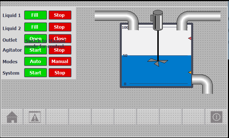
The example that we will build in this tutorial is a batch mixing process. We have liquid 1 and liquid 2 that enter the tank through separate pipes and the agitator mixes them in the tank before the mixture is drained through the bottom drain pipe.
The system is designed to have two modes - Auto and Manual. When the system is in Auto mode all the individual controls disappear and only System Start and Stop buttons are visible. When the system is in Manual mode, individual component controls are visible.
Creating HMI animations can be divided into two steps:
- Adding elements to the HMI screen
- Creating the PLC code and tags, and configuring the HMI components by adding events and animations.
Adding Elements to a Siemens HMI Screen in TIA Portal
Step 1 - Creating a project in TIA Portal
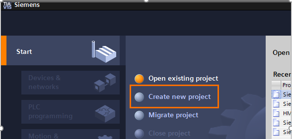
Start by opening TIA Portal from the Start menu.
Once the TIA Portal program starts in Portal view, select Create New Project, enter a new name for the project and click Create new project.
Step 2 - Adding PLC and HMI hardware
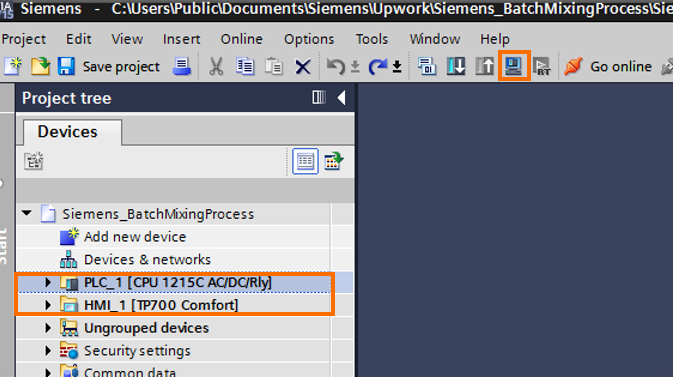
Select Add new device and click Controllers. Expand Simatic S7-1200 and select CPU 1215C AC/DC/Rly from the list. Then click Add.

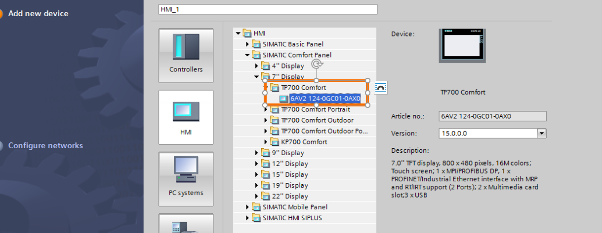
After adding the PLC switch back to Portal View. This time select HMI and select the 7” TP700 Comfort panel part number and click Add.
Step 3 - Adding buttons and text to the screen
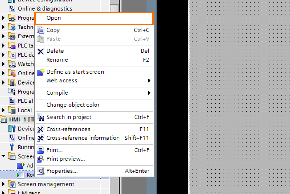
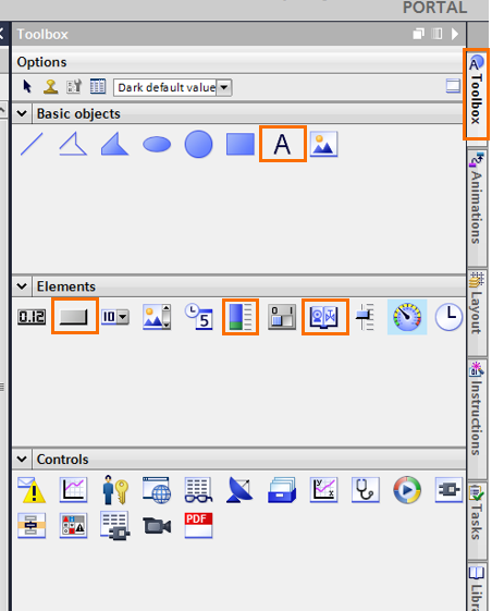
After successfully adding the PLC and HMI, confirm that TIA Portal is in Project view. From the navigation menu on the left expand HMI_1. Right-click on the default HMI screen name and select Open. Once the default screen opens, select the Toolbox on the right side of the window, and then click on Basic Objects.
From the Basic Objects select the Text item and drag it onto the screen. Rename it to Liquid 1.
From the elements section select the 2nd element - the button highlighted in the picture below.
Hovering over the elements with the mouse cursor shows the name of the element. Drag and drop the element onto the screen.
Later in this tutorial we will use the other highlighted elements - Bar and Symbol library which can be converted into different industrial symbols.
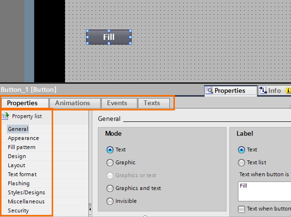
After dragging the button onto the HMI screen, right-click on the button and select Properties, and click on General. Under the Label section change the button label to Fill. Next, select the Appearance section on the left, and change the colors of the button to green.
Make sure to explore the other sections to familiarize yourself with different customizations that are available for the button element.
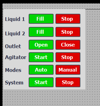
You can now repeat this process to add more text boxes and buttons to create a similar screen to the one shown below.
Step 4 - Adding industrial equipment symbols
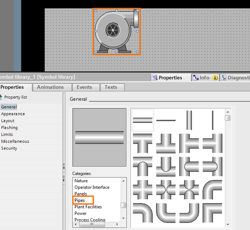
After adding the buttons and aligning them, from the Toolbox tab and Elements section on the right select the Bar item and drag it onto the screen. Right click on the Bar and select Properties. Change the properties of the elements and resize it to match Figure 1.1. Next, go to the Toolbar on the right and from the Elements section select Symbol Library. Dragging and dropping it onto the screen shows a pump object. Right-click on the object and select Properties. In the Properties tab, under the General section scroll through the categories to find Pipes. Select a pipe from this area and resize it as needed.
Copy and paste the symbol a few times and change it to different shapes of pipes and agitator. The agitator/mixer can be found under Categories.
Note that in order to duplicate elements on the screen hold down the Ctrl button, select the object with the mouse and drag. This is the same as copying and pasting but is a lot faster.
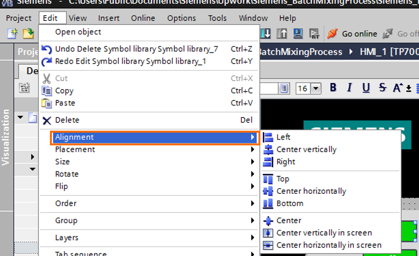
After adding all the necessary elements align them as shown in the example picture - Figure 1.1. To align them, first select the elements. Then from the file menu, go to Edit, Alignment and select one of the options.
Note that when a few objects are selected for alignment, the first object selected is used as the reference point and the rest are aligned based on it.
PLC Programming - Creating Tags and System/Clock Bits
Step 1 - Activating system bits
After adding the PLC hardware to the project :
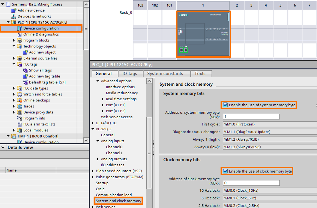
- Select Device Configuration under PLC_1 and double-click it to open the Device view
- Right-click on the PLC CPU in Device view and select Properties.
- In the General tab under Properties, scroll down to System and Clock Memory
- Select both the boxes next to System and Clock memory bits
These system and clock bits now appear as tags in the default tag table along with their addresses.
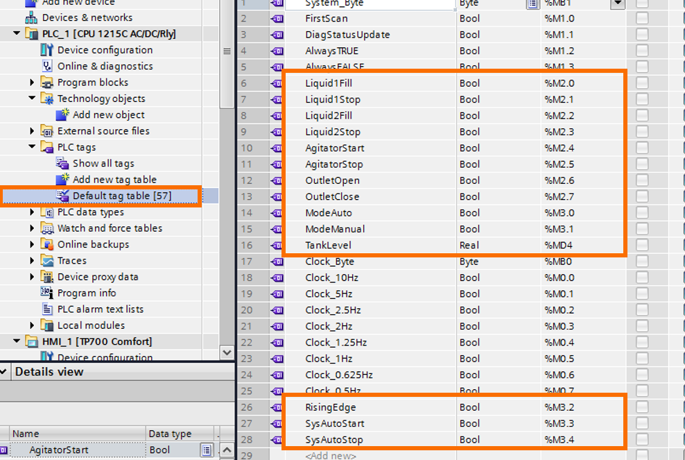
Step 2 - Creating PLC tags
Navigate to the Default Tag Table from the navigate menu on the left and double-click it to open the tags. Add the PLC tags highlighted below. The rest of them are system tags and they appear automatically after enabling the System and Clock bits.
Since we are not using any hardware for this tutorial, these tags and some logic in the PLC program will help simulate the changing signal levels. Refer to the PLC program that is supplied with the tutorial for the complete code and functions.
Step 3 - Creating HMI Animations
After adding all the required PLC tags, switch back to the HMI screen and select the Fill button. Right-click on the button and select Properties. Switch to the Animations tab and create a Visibility animation under Display. Click on the ellipses(...) and select the tag. Repeat this process for all the buttons, text fields and other symbols by selecting the appropriate tags.
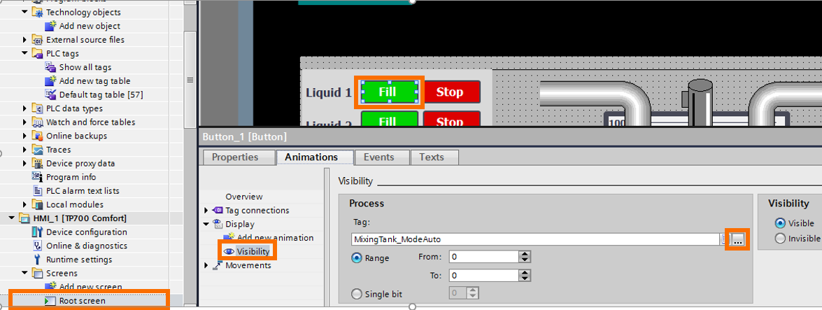
Figure 8.1 - Visibility animation for Fill button
Step 4 - Creating HMI events
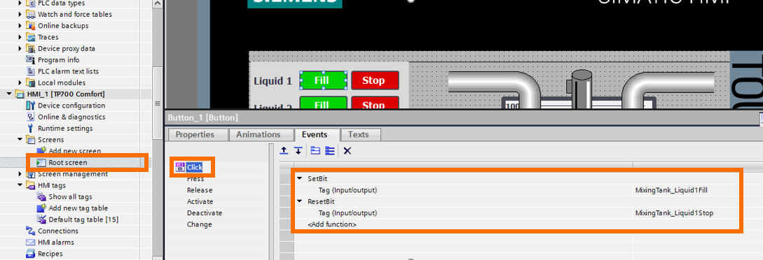
Select the Fill button and right-click to select Properties. Then switch to the Events tab and select the first Event type - Click. Click on the <Add function> and type SetBit and select the tags as shown. A new Add function appears in the next line, click on it and type ResetBit as shown below. Click on the ellipses(...) and select the tag as shown below. Repeat the process for other buttons based on the example PLC program file supplied along with this tutorial.
Step 5 - Simulating PLC and HMI
After completing the PLC code and configuring the HMI elements, simulate both the PLC and the HMI to test the animation. From the Devices list on the left part of the screen select PLC_1 and click on the Start Simulation button to simulate the PLC.
Note that the FW version of the PLC needs to be 4.0 or higher in order to be able to simulate it.
After selecting the Start Simulation button wait for this window to appear and click Load.

On the next screen from the drop-down list select Start module and click Finish.

Once the PLC simulation starts, select the HMI_1 from the Devices list on the left and select the Start Simulation button. This will compile the HMI and if there are no errors the HMI simulation will start. Click on different buttons and notice how the Events defined for each button Set(=1) and Reset(=0) certain bits of the PLC. The Visibility animation determines if objects are visible or hidden during runtime. Appearance animations determine the object’s color and other aspects during runtime.
Finally, Events determine what happens when a button is clicked, pressed, released etc. There are several different types of Events including setting and resetting bits, changing screens and clearing alarm buffers.
Conclusion
Events and animations are powerful features when programming HMIs. In this tutorial we have learned how to add a variety of HMI elements and industrial symbols such as buttons, blowers, agitators and vehicles. We also covered how to change the appearance of the elements, add animations and events to change their runtime behavior. Finally, system and clock bits as we have seen in this example are very useful built-in bits, one such example is the First Scan bit that can be used for startup configuration.
As a follow-up to this, you may try different combinations of animations such as Visibility, Appearance, Events and Movements. If you’re getting started with Siemens PLC programming, make sure to check out this free course.
