Mitsubishi GX Works2 Function Block Programming and Troubleshooting

Introduction
Functions and function blocks store their inputs/outputs in instance data for processing. They help reduce the time spent programming systematic processes/sequences as an instance can be created. Instances are a specific implementation of a defined function. This tutorial introduces the basics of function blocks and troubleshooting methods.
In order to follow along with this tutorial, you will need:
- Familiarity with Mitsubishi PLC Programming with GXWorks2
- An installation of GX Works 2 Software.
Before we delve into function blocks, let us first understand Intelligent Function Modules.
Intelligent Function Modules
As with the device memory in CPU modules, intelligent function module devices can read data from and write it into their buffer memories using transfer instructions like MOVE. They are special modules that can be added to PLC hardware. Some of such modules are analog input, analog output, temperature module, and MODBUS module.
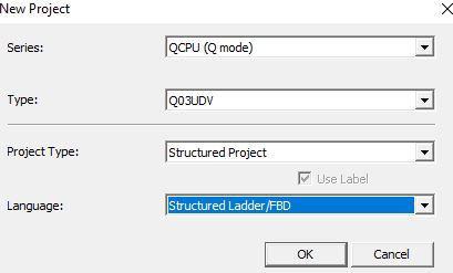
Let us start by creating a new structured project with Q series PLC.
Launch GX Works2 and configure your project as follows
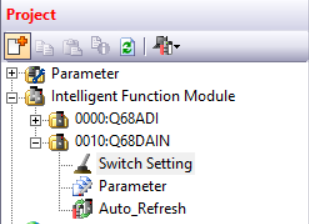
Navigate to the Intelligent Function Module under the project tree.
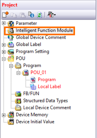
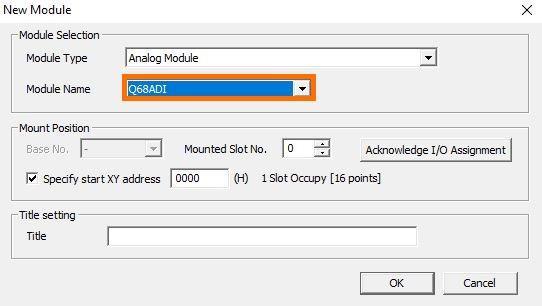
Right click on it and choose “Analog module”. Here you get a list of supported intelligent function module.
The Analog input module is Q68ADI. The Analog output module is Q68DAIN
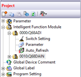
Expand the module. There, you will find Switch Setting, Parameter and Auto_Refresh
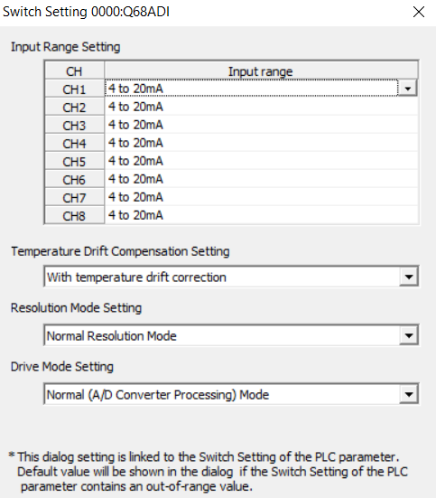
In Switch Setting, the input range is selected. Q68ADI is a mA module
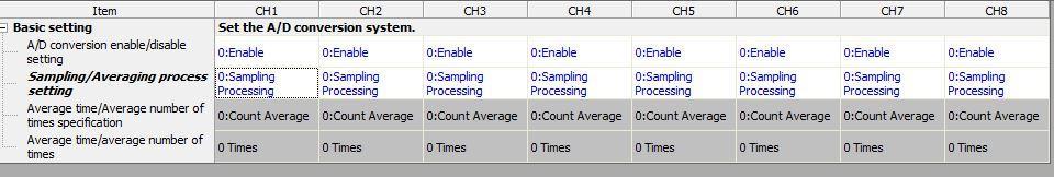
In the “Parameter” setting, the Analog channel can be enabled/disabled
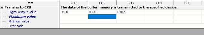
You specify the buffer that will be used in holding the raw data in Auto Refresh.
Compile the project after configuration.
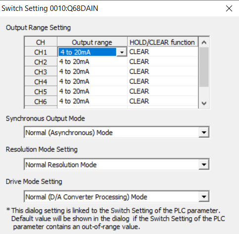
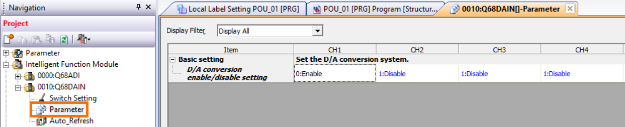
To configure the Analog output (Q68DAIN) module, navigate to the project tree and select ‘’0010:Q68DAIN’'. Expanding the module, select the switch setting and choose your output signal.
Navigate to parameter. In ‘’parameter’’, the Analog channel can be enabled or disabled.
Function Blocks (FUN) in GX Works2
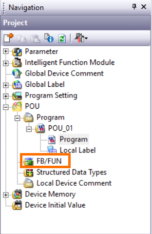
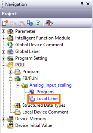
To create a new function block, navigate to POU. Under “Program”, you will find the FB/FUN section for function block (FB) and functions (FUN). Select FB/FUN.
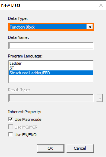
Select Function Block as the data type from the drop down. You can give it any Data Name you desire.
We will be creating an Analog input scaling function block.
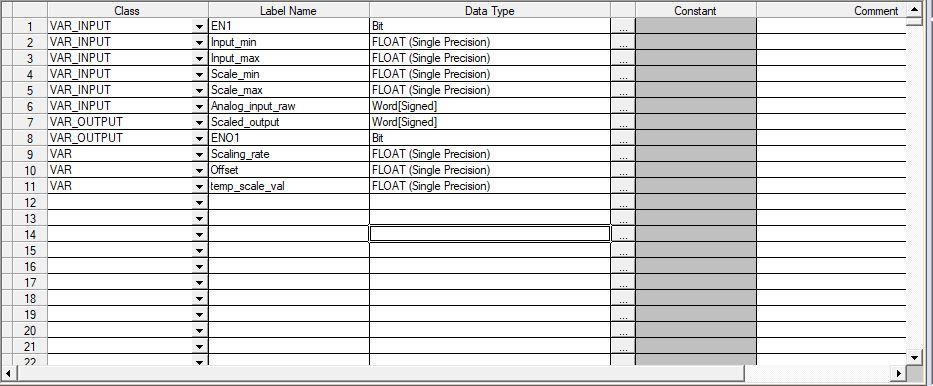
Navigate to the newly created Function block. Expanding the function block, you will see ‘’Local label’’. The local label is the function block’s internal data storage. For the Analog input scaling function, the local label is shown below.
Open the program section of the Function block and write the following ladder code
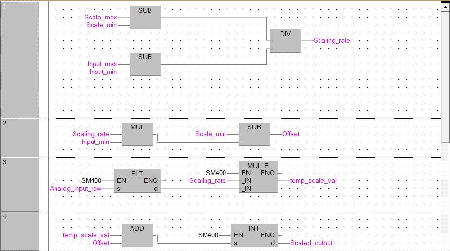
The formula for analog input scaling is given below
[(Scale- Scale min Input- Input min ) x raw analog input] + offset
The division between the scaled value and the input value is done in network one. This is stored as scaling rate.
In network two, the offset is computed by multiplying the scaling rate and the input min, then subtracting them from the scaled minimum.
In network three, the raw analog value is converted from a 32bit WORD to a FLOAT using the instruction FLT. The obtained value is multiplied by the scaling rate. SM400 is an always ON bit.
In network four, the result from network three is added to the offset and then converted from FLOAT to a 32bit WORD.
Compile the function block.
Navigate to POU on the project tree and expand program. Program is the window for programming in ladder.
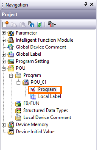
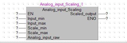
Call the function block in POU_01. Drag and drop the Analog_Input_scaling function block we created into the programming window to call the function block. A prompt will be generated.
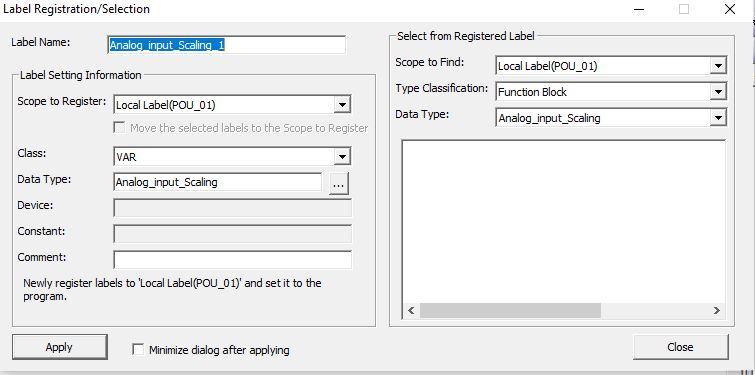
Click “Apply”.
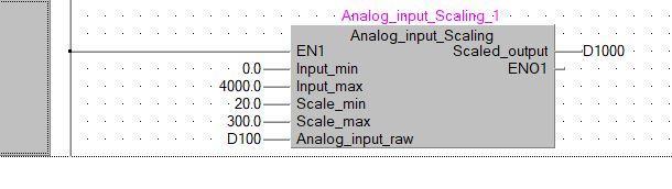
For scaling in Mitsubishi Q series PLC, the Q68ADI Analog input module input max is 4000.
Let us scale a temperature transmitter from 20 oC to 300oC and store it in the D1000 register.
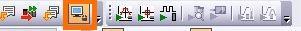
Start the simulator and monitor the program. The start simulation button is at the top right of the menu bars.
Modify the Analog input raw (D100) register to 2000 which is half of the input maximum range.
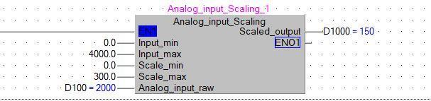
The scaled output is 150 which corresponds to half of the scale maximum.
Troubleshooting with GX Works2
Sampling Trace
The sample trace function captures the data at a predetermined time to track changes in device values throughout program execution. The changes are displayed as time series.
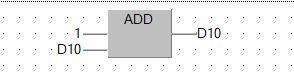
Let us write a simple program of changing values to monitor the trace.
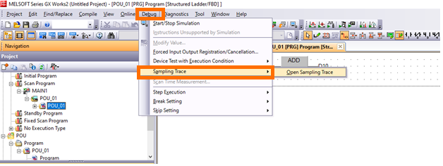
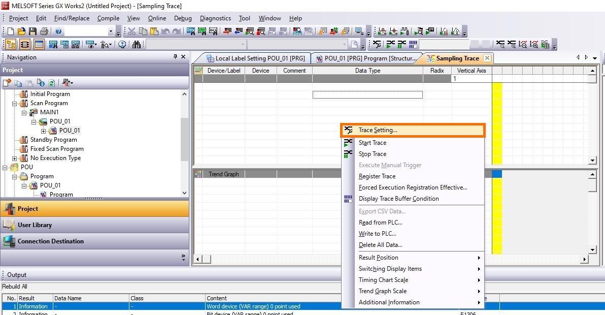
To begin Trace, start the simulator. Then select debug and sampling trace.
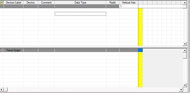
A window like the image shown below is seen
While on the Sampling Trace window, Right-click and select sample trace settings.
Trace execution methods set the trace execution to either execute after overwriting current trace settings in the PLC or execute the trace with the existing settings in the PLC.
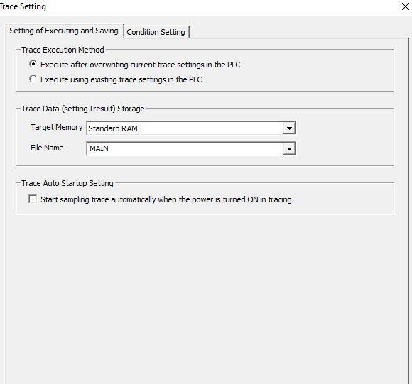
The trace data storage setting specifies the location of storage of the trace.
Trace auto start-up starts sampling trace immediately after the CPU is put into run mode.
Condition settings determine the trace count, data acquisition timing setting, and trigger conditions.
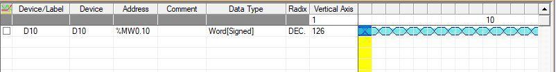
We want to perform a trace on D0 register. Input D0 in the trace window as shown below.
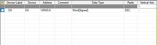
The vertical Axis display the time axis data of the selected cell as the trace result. The data type column can be changed after registering the trace.
To begin trace, Right-Click while on the trace window and select ‘’Start Trace’’.
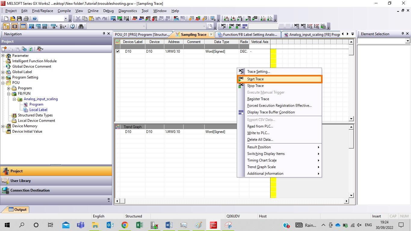
The trace starts and displays the trace data storage status
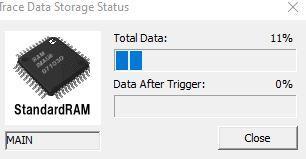
Total data: Displays the current data acquisition (sampling) status in relation to the number of times specified in the "Trace Setting" as a percentage. Even when this state reaches 100%, a sampling trace is continually run, overwriting the most recent data with the newer ones.
Data after trigger: Display the current status of data acquisition (sampling) after the trigger generation in the percentage of the number of times set for "Trace Setting". When the status reaches 100%, the sampling trace stops.
After completion or stopping of the trace the following results shows
Double clicking on the trace will give you the value at different timing chart.

Cross Referencing in GX Works2
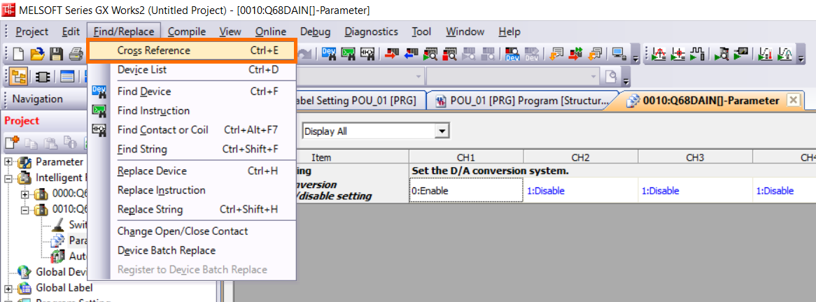
Cross Referencing is another skill to be learnt from troubleshooting. To cross reference any device, navigate to find/replace under the menu bar and select cross-reference.
The cross reference window opens underneath the programming window as seen below
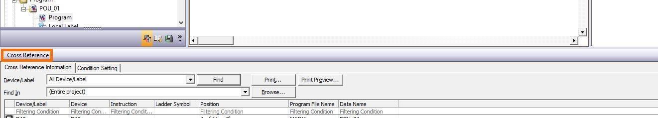
The device/label section is where you specify the device address you want to cross reference. We will be cross referencing D10 device. Under the device/label column input D10.
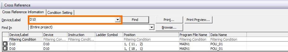
From the image above, the device D10 is cross referenced and found in the MAIN1 program. Clicking on each of the results of the cross-referenced device will take you to the network where it is used.
Conclusion
Using function blocks with GX Works2 is a crucial knowledge needed to be a well-grounded PLC programmer with Mitsubishi PLCs. Function blocks make the flow of code easy and more intuitive to follow, encouraging block reusability. Troubleshooting skills are also one to have under your belt because there might be times when it will be needed in the face of seeming challenges. We will encourage the programmer to spend more time practicing more examples using function blocks.
