Opto 22 groov RIO Getting Started

Introduction to groov RIO
The groov RIO module from Opto 22 has been released only a few months ago. The groov RIO is a feature packed piece of hardware that is easy to install, configure and deploy for many different field applications. The module comes pre-loaded with an array of software tools used across the industry and is ready to hit the floor running out of the box. Furthermore, the module is equipped with user configurable input and output nodes that have the capability unlike anything else on the market.
The groov RIO can be used in systems that already employ other control systems or as a completely stand-alone device. The module can send data through local protocols such as Modbus/TCP as well as publish data to remote and cloud solutions such as MQTT, Node-RED and Ignition.
In this article, we will cover initial configuration steps of the module as well as provide examples of projects users can get started with.
RIO Out of the Box
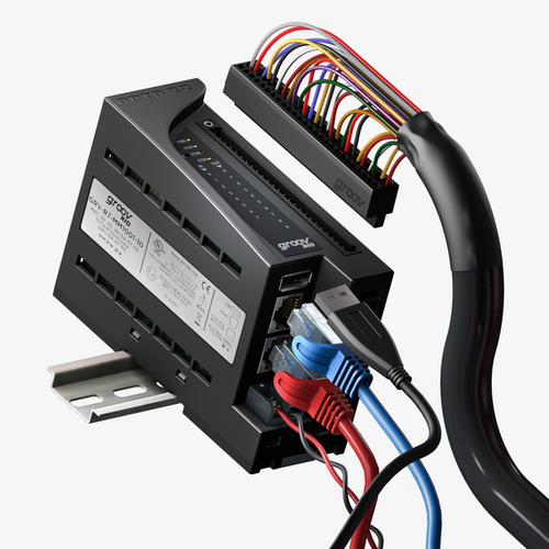
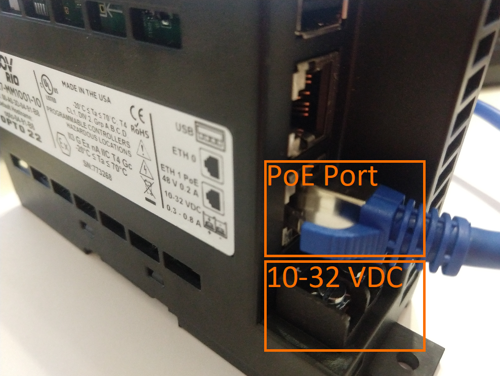
The RIO module is extremely easy to get started with. The user can choose to power the module over PoE (Power over EtherNet) using a PoE capable switch. The second option is to power the module directly with 10-32 VDC. We believe that the two options are available depending on what the use case will be. In an industrial enclosure, it’s typically easier to get a 24VDC signal, while within an IT cabinet, PoE will be more common. In either case, Opto 22 has got you covered.
Connecting to the groov RIO
The RIO arrives with a host name on the side label. You will be using this information to connect to your module.
Set your Network Card to DHCP
Step 1 - Navigate to Control Panel > Network and Sharing Center > Change Adapter Settings.
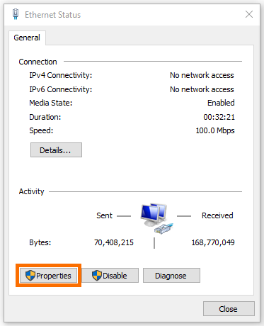
Step 2 - Double Click on your Adapter > Properties.
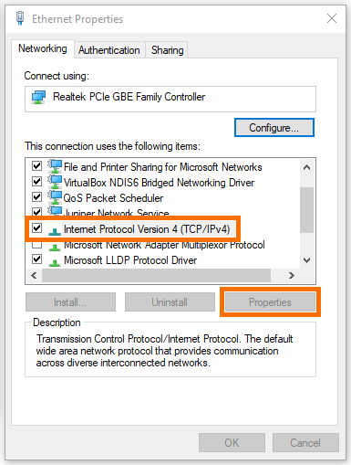
Step 3 - Select “Internet Protocol Version 4 (TCP/IPv4)” > Press “Properties”.
Step 4 - Select “Obtain an IP address automatically”.
Step 5 - Select “Obtain DNS server address automatically”.
Step 6 - Press OK.

Connecting to groov RIO
Step 1 - Power ON the module as shown above over a PoE Switch or a 10-32VDC Power Supply.
Step 2 - Record the “Default Hostname” written on the label of the module.
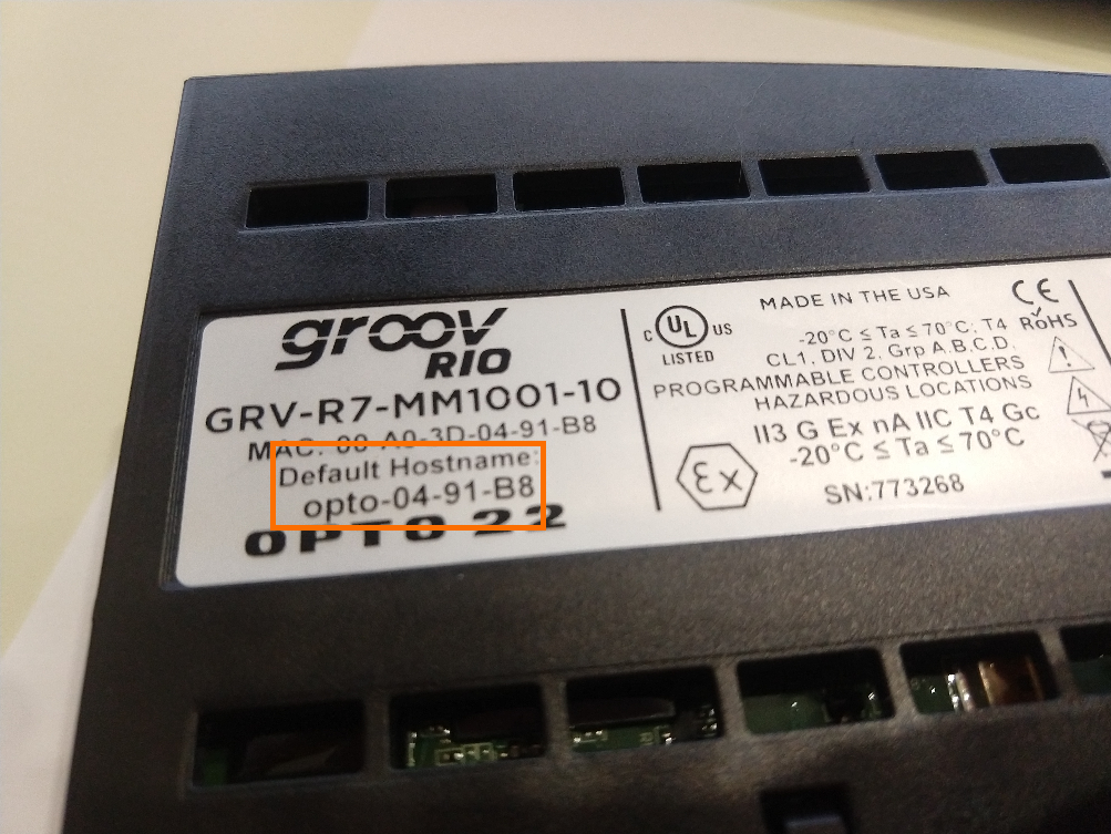
Step 3 - Open a Browser and Type in https://opto-04-91-b8/ (With your hostname replacing “opto-04-91-b8”)
Configuring Opto 22 groov RIO Basic Settings
An account will have to be created during the start-up sequence of the RIO module.
Changing Network Settings
We’ve used DHCP to access the groov RIO. However, in an industrial environment, the device is much more likely to have a static address assigned to it.
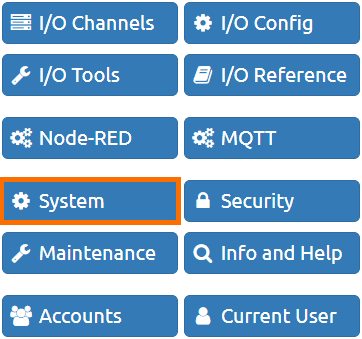
Step 1 - Navigate to the “System” Settings.
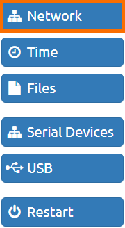
Step 2 - Select “Network” Settings.
Step 3 - Select “Configure”.
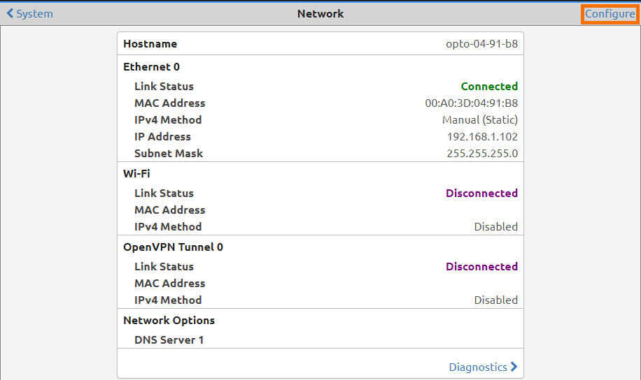
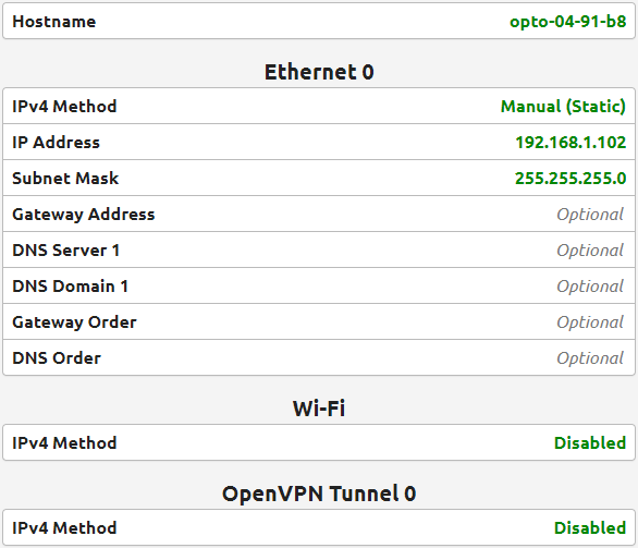
From this menu, the user can configure the settings of the network adapters of the groov RIO module. We recommend that you select the configuration that best suits your organization. As an example below, we’ve configured the groov RIO to be placed on our private network with an IP of 192.168.1.102
Creating Users and Administrators
The groov RIO will allow the user to create an Administrator level user during the setup process. However, you may want to change this username or add additional users that may have the same or less access to the module. For example, you may want give restricted access to technician level personnel for troubleshooting purposes once the system is deployed.
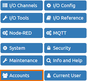
Step 1 - Navigate to the “Accounts” Settings.
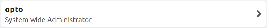
Step 2 - Select the “opto” user.
Step 3 - Change the username and password.
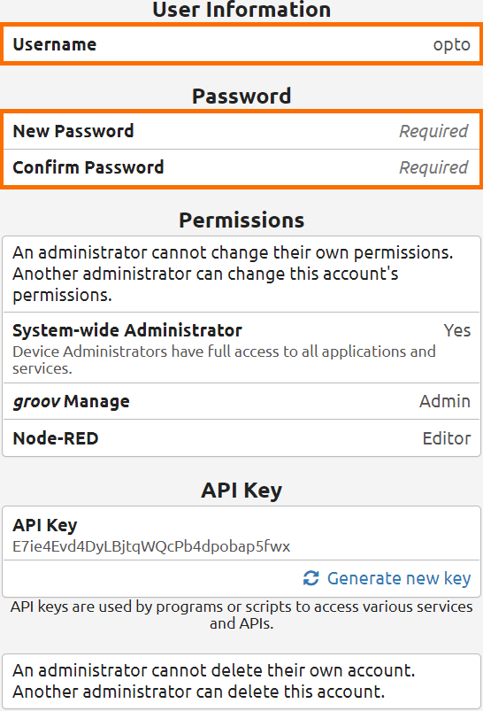
[Optional] Step 4 - Create “New” Users with specific permissions.
Changing the Hostname
The hostname will dictate the URL through which you connect. Although you may navigate directly to the IP address, it’s helpful to have an easy-to-remember name for your system that facilitates navigation for non-IT savvy users.
Step 1 - Navigate into “Network Settings” (See above).
Step 2 - Change the “Hostname” to the desired name. See example below of our setup for “SolisPLCRIO1”

Step 3 - Connect to the groov RIO over the new hostname.
Ex: https://solisplcrio1/
groov RIO Input and Output Configuration
One of the key features of groov RIO is the configurable input and output nodes. In fact, unlike any other system on the market, the user may configure the channels to act as digital inputs, analog inputs, digital outputs or analog outputs.
Here’s a complete breakdown of the configuration available for each channel. We recommend that you review this chart or use the one from the data sheet to configure your module. Not every permutation is available on every channel.
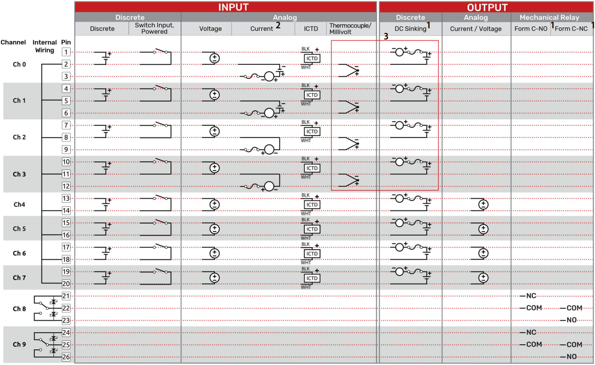
Warning - the notes below apply to the channel configuration displayed above.
Note 1 - “You must supply external fusing.”
Note 2 - “Opto 22 recommends adding external fusing. Review the specification table for specific ratings. Compatible with an externally powered or self powered transmitter. Wiring for the externally powered transmitter is shown on channels 0 and 1. Wiring for a self powered transmitter is shown on channels 2 and 3”.
Note 3 - “Thermocouple inputs and discrete sinking outputs cannot be mixed on channels 0-3.”
Configuring an I/O Channel in groov Manage
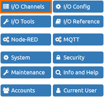
Step 1 - From the “Home” Screen, Select “I/O channels”
Step 2 - Select a Channel to Configure.
Step 3 - Select “Configure”
Step 4 - Give the Channel a Name under the “Name” field.
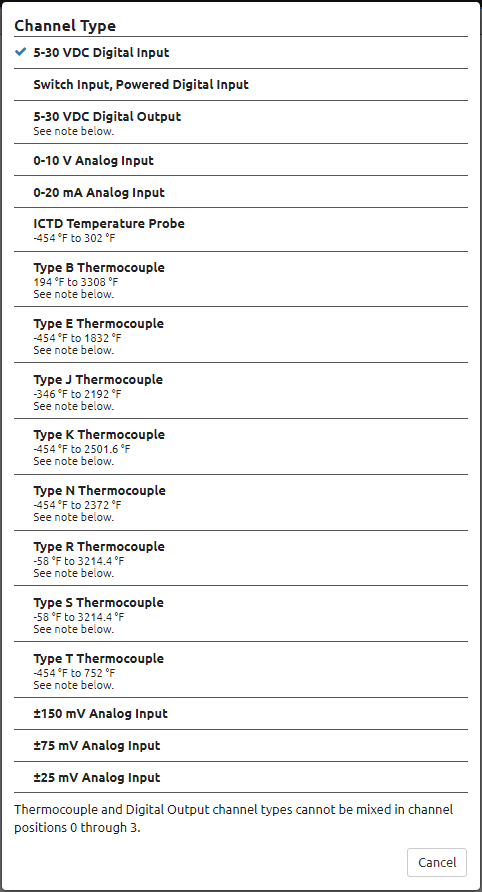
Step 5 - Configure the “Channel Type” per the diagram above.

See an example of Channel 0 configuration below.
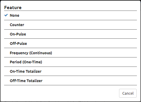
[Optional] Step 6 - Configure optional features of the channel. Ex: Additional Features supported by the I/O configured.
See an example of features available for Channel 0 below.
Note that not all of them may be selected for the above configuration (Digital Input).
Step 7 - Press “Save” to confirm your selection.
Working with Node-RED
Node-RED is a powerful tool that extends the capabilities of the groov RIO module. Node-RED is a platform that facilitates software development through libraries and modules that can be configured and tied together in order to execute a set of tasks.
The groov RIO experience centre comes with a basic demonstration of Node-RED features. In this brief overview, we will review the functionality of the program and extend it through our own modules.
Accessing the Node-RED editor
Step 1 - From the “Home” Screen, press “Node-RED”.
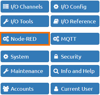
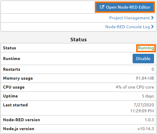
Step 2 - Verify that Node-RED is currently “Running”
Step 3 - Open the “Node-RED Editor”
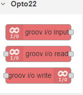
The Node-RED installation will come with an “Opto22” library which allows the user to tie in the Inputs and Outputs into Node-RED.
Note that a “default” installation of Node-RED will not contain this library.
The default program of the groov RIO experience centre will turn on a relay based output when the temperature exceeds a certain setpoint and turn off the same relay channel when the temperature falls below the setpoint. Let us examine this program in Node-RED.
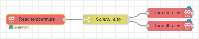
Step 1 - Temperature Monitoring
In order to monitor the temperature, a groov i/o input module is used with the following configuration:
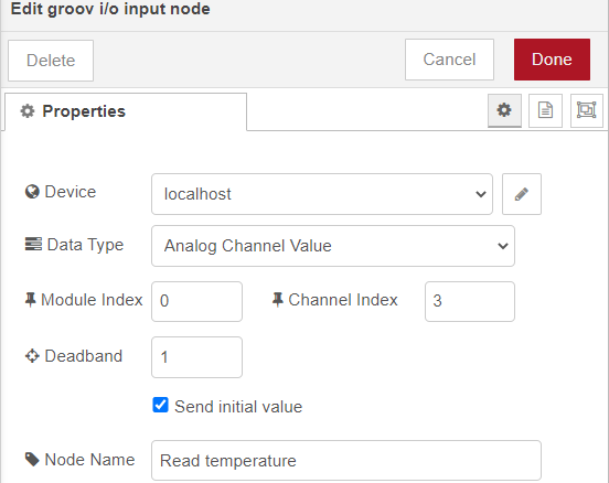
Note three key parameters of this configuration:
Device - “localhost” indicates that the data is coming from the groov RIO module on which Node-RED is running.
Data Type - “Analog Channel Value” indicates that the data to be read by Node-RED is of analog type.
Channel Index - “3” indicates that the data must be collected from Channel 3.
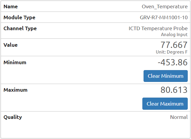
Note: it’s important to note that Channel 3 has been wired to a temperature probe and configured to receive analog data as shown below:
Step 2 - Verification and Decision
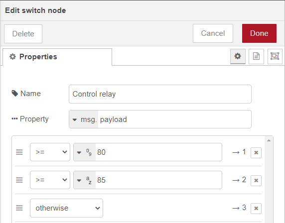
The second block used in the diagram is a switch node. This node will take a certain piece of information and decide which path to execute. Note that this block may contain two or more paths.
In our example, the following configuration is used:
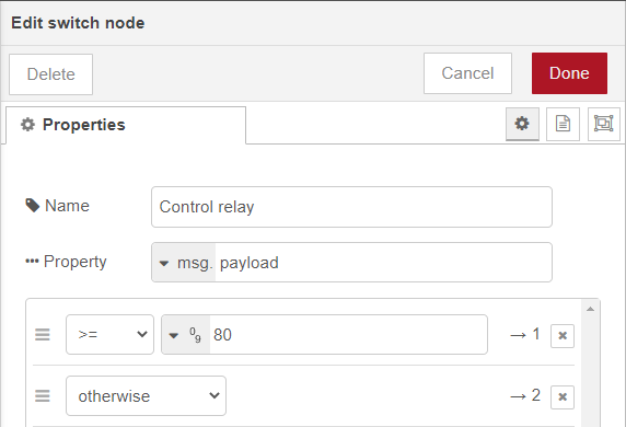
Note three key parameters of this configuration:
Property - “payload” indicates that the data to be used in the block comes from the payload retrieved from the channel.
First Condition - “>=” and “80” indicate that this condition will be true when the value sent by “Channel 3” is above or equal to 80.
Second Condition - “otherwise” indicates that this condition will be true when the First Condition is not met (When the temperature is strictly below 80).
Step 3 - Action / Execution
The final step of our Node-RED program is to act upon the second step. In the demo, this equates to turning on and off a relay based on the temperature threshold. The blocks used to perform this operation are of type “groov i/o write”. One is needed to turn on and one to turn off the relay. The following configuration is set for each one:
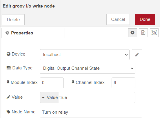

Note three key parameters of this configuration:
Device - “localhost” indicates that the data is coming from the groov RIO module on which Node-RED is running.
Data Type - “Digital Output Channel State” indicates that the data to be set by Node-RED is of digital type.
Channel Index - “9” indicates that the output to be turned on and off is on Channel 9 of the groov RIO.
Value - “true” and “false” indicates the state to which the channel is set. When the temperature is above 80, the state is set to true; when it’s below 80, to false.
Making Changes to the Node-RED configuration
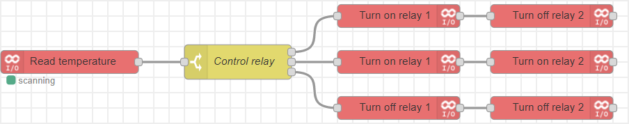
It’s easy to add or change the functionality of the Node-RED program we’ve encountered above. For example, we can create an “Alarm” and “Fault” scenario by utilizing both relay modules. In other words, we will have a limit above which the first relay will Turn ON and a limit above which both relays will Turn ON. This practice is common in control systems as you’d want a warning before your system enters a failure point and needs to shut-down. Let’s explore this in the Node-RED editor.
Note: there are several ways in which we can implement the logic above. The example below represents one of them.
Further Extending the Node-RED application
We’ve barely scratched the surface of the capabilities of Node-RED with the demonstration above. You can send emails, update servers, send data, control devices through Amazon Alexa, Google Home and much more. We highly recommend the following set of tutorials when it comes to Node-RED. You will learn how to build advanced applications that can be leveraged by the groov RIO:
Conclusion
The Opto 22 groov RIO comes packed with hardware and software features. However, it’s important to go through the setup process in order to get you started on the platform. We recommend that every user goes through the steps above in order to get their controller onto the network, the IO configured and Node-RED setup for production.
If you have any questions about the groov RIO or otherwise, don’t hesitate to reach out to us through the forums.
