Photo Eye Sensor | How to Wire a Photoelectric Sensor into a CompactLogix Allen Bradley PLC

Photo Eye Sensor Introduction
A Photo Eye is one of the most fundamental field devices within a manufacturing environment. Such sensors typically send an ON or OFF signal back to an input of a PLC and are used in various applications in manufacturing automation. Such applications include the presence of product, the presence of a safety feature, a system level and more.
As a control systems engineer, technician, electrician or operator, it’s important to know the basics of working with photoelectric sensors, understand the basics, how to wire them, how to tie them into various PLCs and field devices and lastly how to troubleshoot them.
The Basics of a Photo Eye Sensor
A Photo Eye will emit an infrared signal and capture the signal reflected back to it. Based on what’s placed in front of the sensor as well as the parameters of the device, it may turn on or turn off. In addition to a single beam, certain photo eyes are combined with a reflector across the target. Doing so allows for more precise detection and less erroneous triggers caused by the external environment.
As previously mentioned, photo eyes are input devices to a controller, PLC or a remote IO module. They come in many electrical configurations. Generally, they’ll require connections to a voltage source, ground and return a single point that will send a HIGH or LOW signal depending on the status. We’ll explore the exact wiring of a sensor below.
Common Photoelectric Sensor Types
There are three main types of photoelectric sensors on the market. It is important to understand the differences that make them unique and which one is applicable for a specific project. In general, an application may require a certain type of sensor or be satisfied with either type.
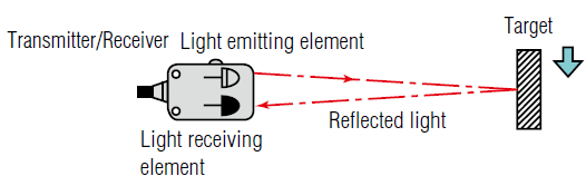
Reflective Photo eye
The most cost-effective sensor will contain both the emitter and receiver within the same housing. The reflective photo eye will emit an infra-red signal and capture it when an object is placed in front of it. Once the object reflects the signal, the photo eye is set and the signal is sent back to the programmable logic controller.
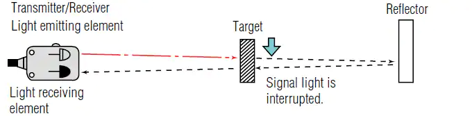
Retro-reflective Photo eye
A retro reflective photo eye will require an additional component: reflector. This reflector is placed directly in the beam of the sensor and reflects it back to the receiver. The reflector is coated in a special paint that will only reflect the signal of the sensor. In other words, while there is no object between the sensor and the reflector, the sensor will receive the returning signal. When the beam is blocked by an object, the sensor will report an alternate state. The advantage of the retro-reflective sensor is that it’s highly reliable. Furthermore, it’s easy to identify that there is an issue within the system since the sensor will not return to a normal state if the reflector is no longer in position. The disadvantage of this sensor type is that the cost is higher and requires a mounting location for both devices across from one another.
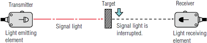
Through-beam Photo eye
The third type of a photo eye is through-beam. This type of a sensor comes in two devices; one is an emitter and the other a receiver. They are placed at opposite locations and a beam is passed from one to the other. An object that comes through the beam will force the sensor to toggle to the opposite state. The advantage of this setup, just like the retro-reflective type is that it’s much more reliable than the reflective photo eye. However, this layout is costly and requires additional considerations when it comes to the hardware.
There are types of through-beam sensors that contain both the emitter and receiver within a single device opposing each other. This setup provides a reliable way to sense an object, but may only fit applications of set dimensions.
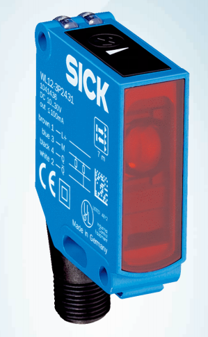
Example of a Photo Eye - SICK WL12-3P2431
The WL12-3P2431 is an excellent low cost photo eye from SICK. The sensor is paired with a retro-reflector and is equipped with a potentiometer that will adjust the sensitivity of the device.
SICK WL12-3P2431 Photo Eye Wiring Directions
The documentation of the installation instructions can be found on the manufacturer’s website. However, the connections may not be obvious. Let’s discuss the four pins of this specific sensor in detail.
Step 1 - Photo Eye Wiring Scheme
The standard in industrial automation is to run a 4 wire M12 connector to field devices. The 4 pin M12 plug (standard) is broken down as follows:
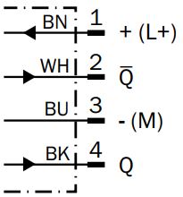
- Brown - 24VDC from Power Supply
- White - Signal 1
- Blue - 0VDC (ground) from Power Supply
- Black - Signal 2
Based on what we find in the datasheet of the sensor, the wiring is standard for the SICK WL12-3P2431 photo eye. The diagram below is what specifies the wiring.
Step 2 - Device Power Requirements
The sensor may be powered by a power supply that meets the power requirements specified by the manufacturer. In the case of the SICK WL12-3P2431 photo eye, the supply voltage must be within the 10 VDC to 30 VDC range. Furthermore, the sensor will consume up to 30mA of current.

Step 3 - Output Specifications PNP/NPN
The SICK WL12-3P2431 photo eye provides a PNP switching output. This means that the input that the sensor will tie into has to be of the sinking type. There are three types of sensor outputs the user should be familiar with: contact, PNP and NPN. A contact based output will close or open an input signal and will be flexible in the type of signal fed into the sensor. The trade-off is that a mechanical contact is much slower than a solid state output. The PNP and NPN variants will require inputs of the sinking and sourcing type respectively. A mismatch of sensor output and input will not allow the device to function as expected.
The wiring example below displays a wiring scheme of the SICK photo eye using an Allen Bradley 1606-XLE power supply and a CompactLogix L16ER programmable logic controller. The controller is equipped with on-board IO that allows the sensor to be wired directly into the controller without the need of additional hardware. Once the signals are passed to the controller, a PLC programmer will see the status of the sensor on the local input points.
Conclusion
A photo eye, or photoelectric sensor, is the most common field device in industrial automation. These sensors are used to sense manufactured objects, state of mechanical objects, safety devices and more. The three most common types of photo eye sensors are through-beam, reflective and retro-reflective. Each type has a purpose and application type. However, they do differ in cost as well as installation requirements that typically constrain the application.
A SICK WL12-3P2431 photo eye is an excellent example of a basic ON/OFF PNP sensor. The wiring diagram dictates a standard configuration which requires a +24VDC and GND signals for power. The sensor has two outputs that may be tied into a programmable logic controller input of the sinking type.
If you're curious about capacitive sensors, check out this tutorial - Capacitive Proximity Sensors Explained
