PLC MQTT Communication Using TIA Portal, Mosquitto and Node-RED

Introduction
In the industrial environment, efficient and reliable communication protocols ensure seamless connectivity and data exchange between various devices and systems. One such protocol that has gained widespread popularity is MQTT (Message Queuing Telemetry Transport). MQTT operates on a publish/subscribe model, where devices are connected to a central hub known as a broker. This makes MQTT particularly suitable for the industrial setting, where multiple devices need to exchange data without direct communication. Instead, they publish data on specific topics on the broker, and any interested recipients subscribe to those topics, receiving the relevant data. MQTT's scalable nature and ease of implementation make it an ideal choice for industrial automation scenarios.
MQTT and Node-RED are two powerful tools that greatly simplify implementing industrial communication in the Siemens environment using TIA Portal. Node-RED is an open-source flow-based programming tool that allows users to wire together hardware devices, APIs, and online services. It provides a visual interface for creating communication flows and integrates seamlessly with MQTT. On the other hand, implementing MQTT in the Siemens environment is made effortless by utilizing the LMQTT library, which contains a set of communication functions, including MQTT, provided by Siemens.
In this tutorial, you will learn how to establish MQTT communication between a Siemens PLC and Node-RED using Mosquitto (as an MQTT broker) and the LMQTT library. The tutorial starts by guiding you through the setup of the Mosquitto broker. Then you'll learn how to create MQTT nodes in Node-RED. Next, we will shift to the TIA Portal side, importing the LMQTT library and using it to perform MQTT communications. Finally, we will use a PLCSim Advanced and a watch table to test the MQTT communication on the PLC side and observe data exchange between the PLC and Node-RED.
Prerequisites
To follow this tutorial, you will need an installation of Node-RED, TIA Portal, Mosquitto broker, and PLCSim Advanced. We will be using the latest versions to date, but you can use any other version. No additional hardware or software is required
Mosquitto/Node-RED side
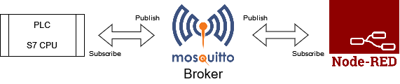
MQTT is a protocol based on a publish/subscribe system. The devices are all connected to a central hub called a broker. If a device wants to send data to another one, it publishes it on the broker under a particular topic. Then, the broker relays it to the recipients subscribed to that topic. Elements do not communicate directly but through the broker by publishing and subscribing to topics. Making MQTT one of the easiest protocols to implement with the easiest scalability.
This tutorial will use a simple MQTT architecture using Mosquitto as the MQTT broker. The PLC and Node-RED server will communicate by publishing and subscribing data to the Mosquitto broker.
We start by running the Mosquitto broker. For this, open a Command Prompt (as an Administrator). Use “cd” to move to the directory where Mosquitto is installed. Then, use the Mosquitto -v -c “path_to_configuration_file” command to run Mosquitto using the configuration file.

In the same folder, you will find a file named “mosquitto.conf, " the configuration file for the Mosquitto broker. By default, it is empty. Open using any text editor (in Administrator mode) and add the following line.
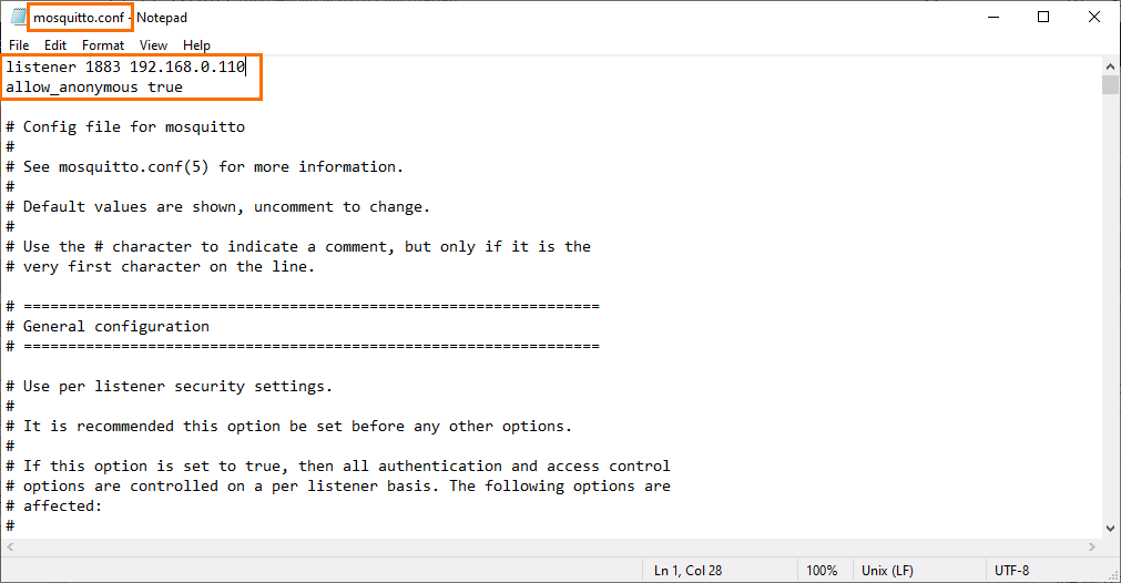
Allow_anonymous true allows any peer to connect to the broker without authentication.
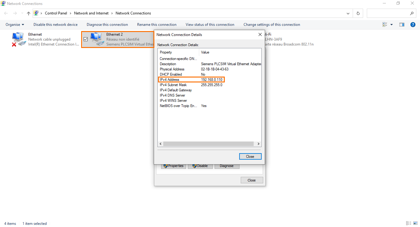
Listener 1883 192.168.0.110 is used to bind the broker to the 1883 port (default MQTT port) and the 192.168.0.110 IP address (The same IP address as the PLCSim Advanced virtual adapter. This will be relevant later in the tutorial).
We now have a configured and running Mosquitto broker. We can head to the Node-RED side. Open Node-RED in your web browser using the “127.0.0.1:1880” (or localhost:1880) address. Then, scroll down the node list to find the two MQTT nodes (MQTT In and MQTT Out) and drop one of each node in the workspace.

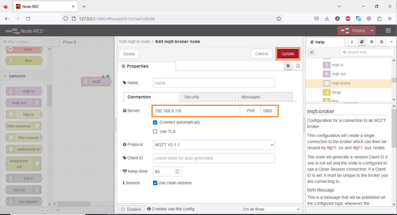
Double-click on the MQTT In node to open its properties. Then, click on the edit icon to add a new broker server.
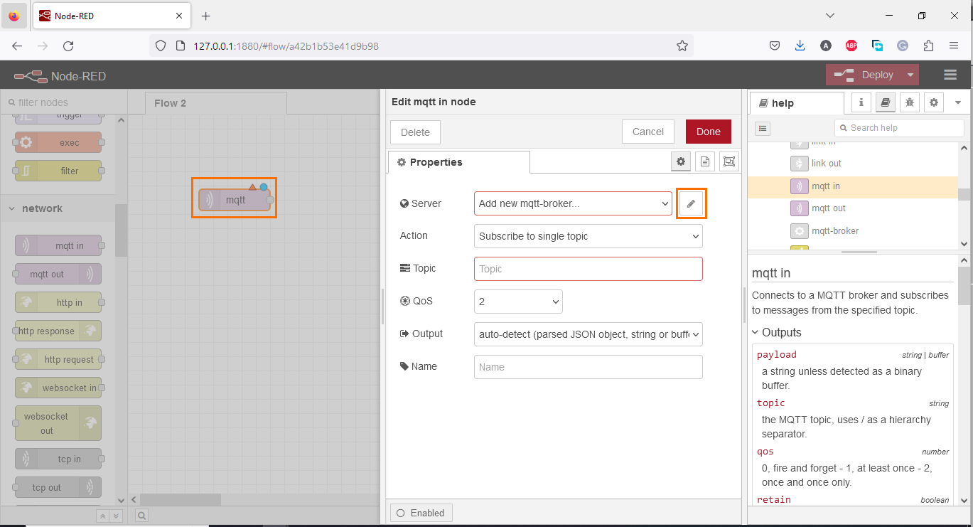
Add the IP address and the port bound to the broker and click on “Update”.
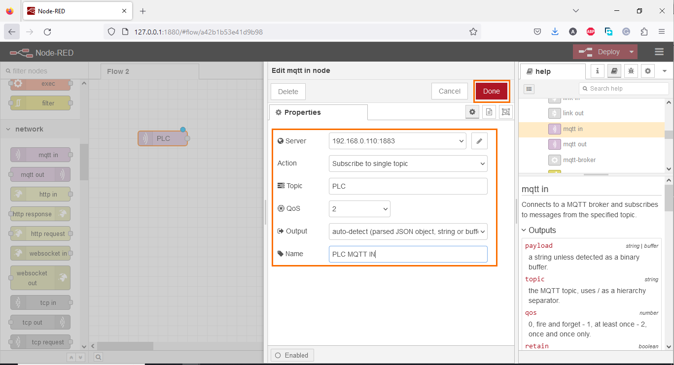
After that, Add the Topic (we will use “PLC” as the topic) and give a name to the node.
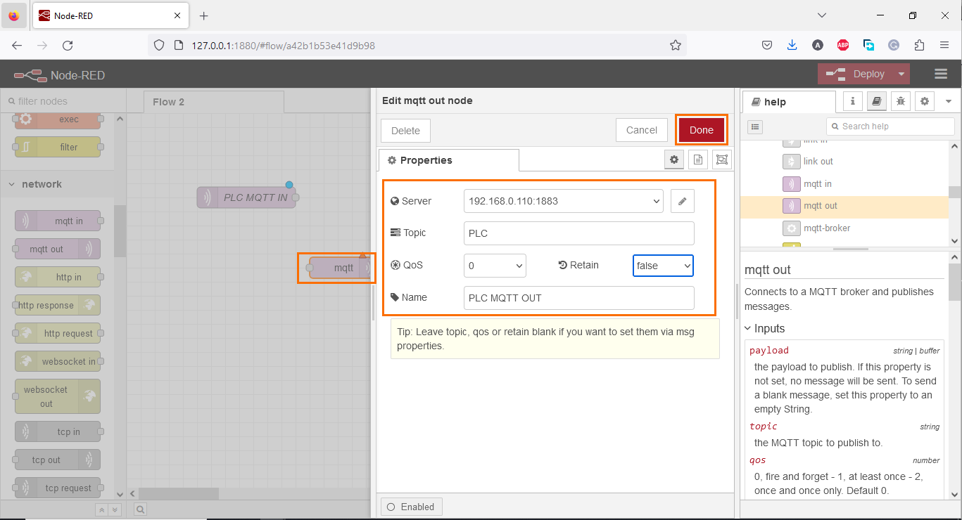
Repeat the steps but for the MQTT Out node (Broker address, topic, and node name).
The nodes are now configured. You can add and link an inject node to the MQTT Out node. This will be used to publish data (Send). Then, link a debug node to the MQTT In node. This will be used to subscribe data (Receive).
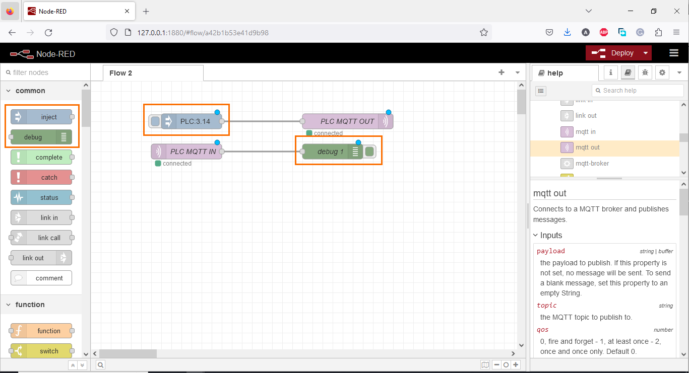
The Node-RED and Mosquitto configuration is now complete.
TIA Portal side
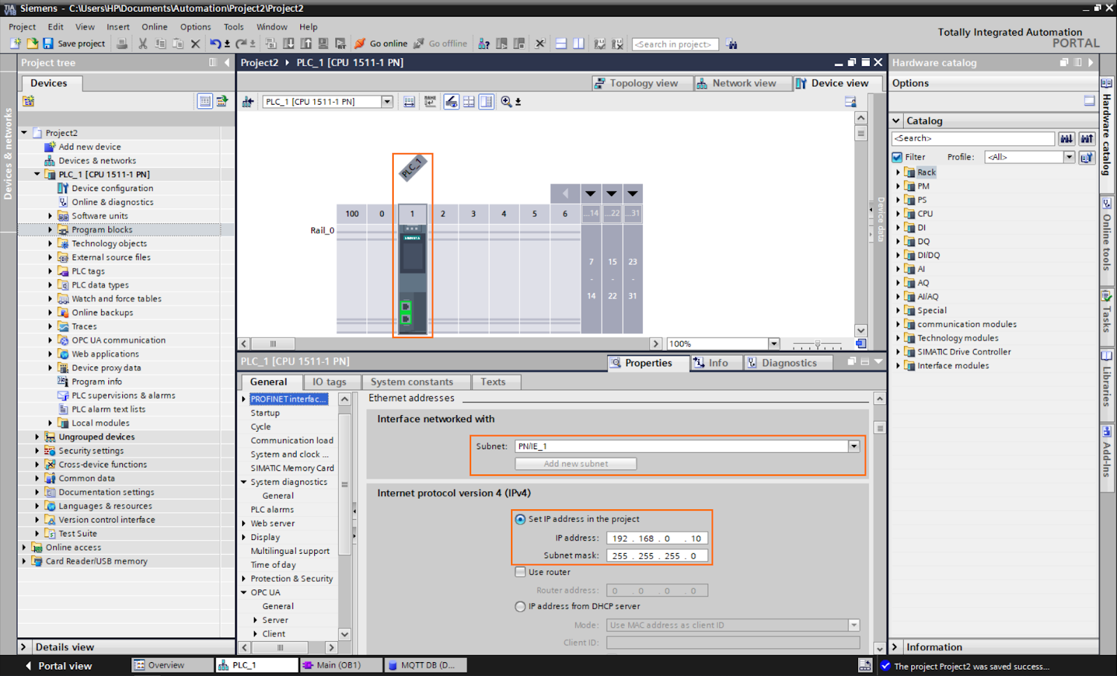
Now let’s head to the TIA Portal side. Let’s start by creating a new project, add the CPU of your choice, and editing the ethernet parameters of the CPU (You can choose the IP address of your choice).
To perform MQTT communications, we need to use a communication library provided by Siemens containing a set of communications functions, including MQTT. You can download this library (and its documentation) here.

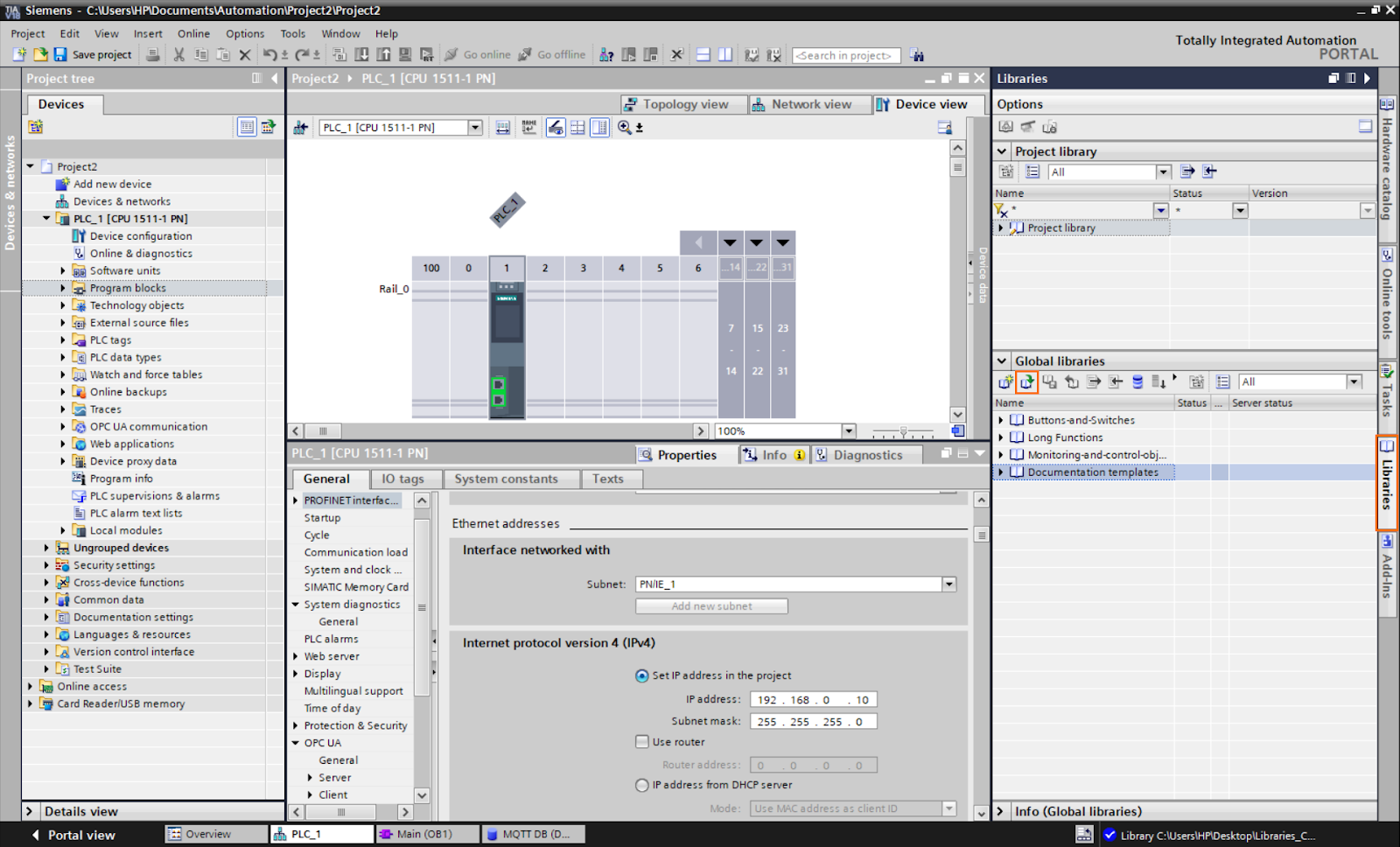
Once the library is downloaded, we must add it to the TIA Portal project. Open the “Libraries” tab and click on “Open a global library.”
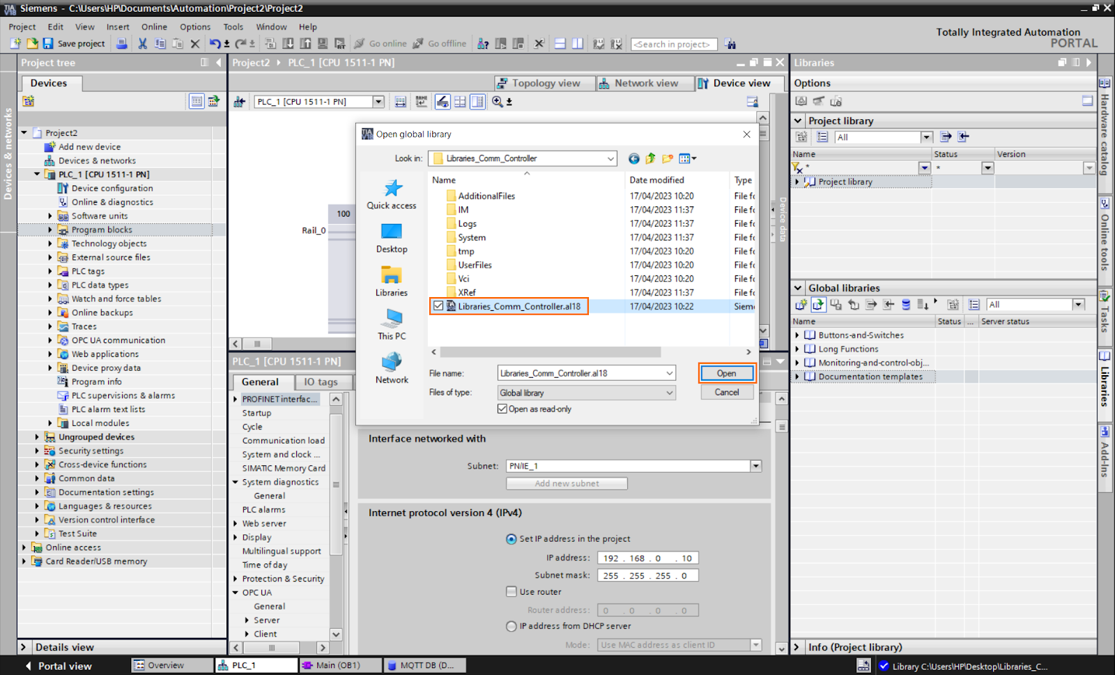
Go to the location where you unzipped the library and select the .a18 file.
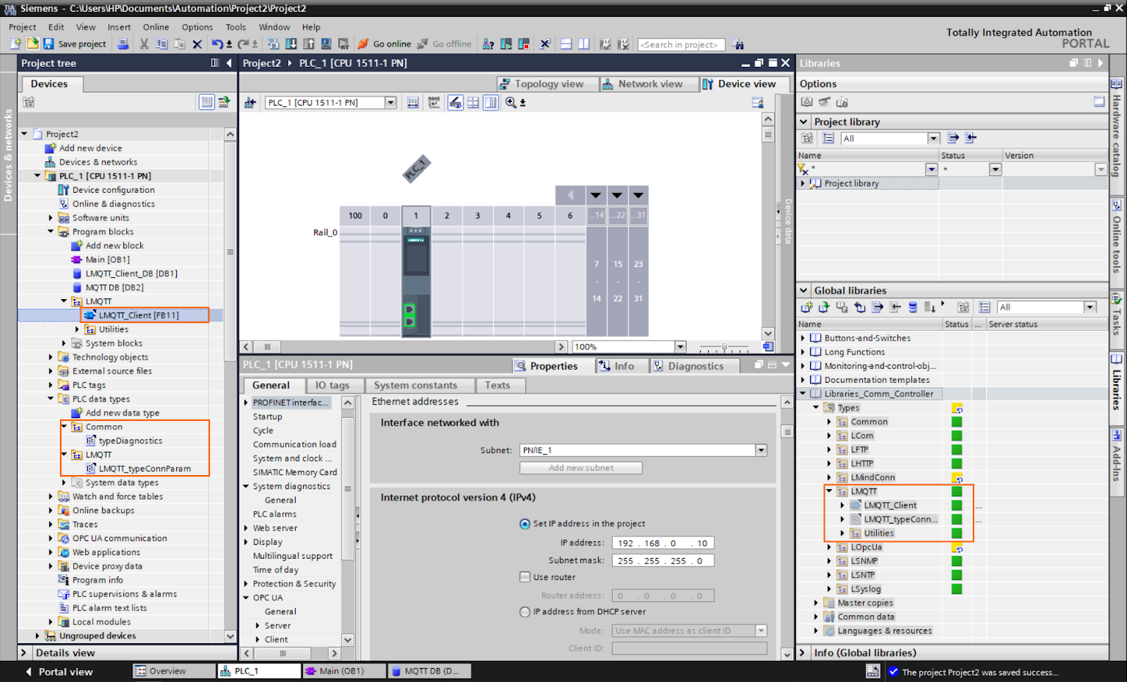
Open the library and LMQTT folder in the “Types” section and copy the “LMQTT_Client” function to your program. It should also automatically add its associated data types.
After that, open the main program and drag and drop the “LMQTT_Client” function from your program to the first network.
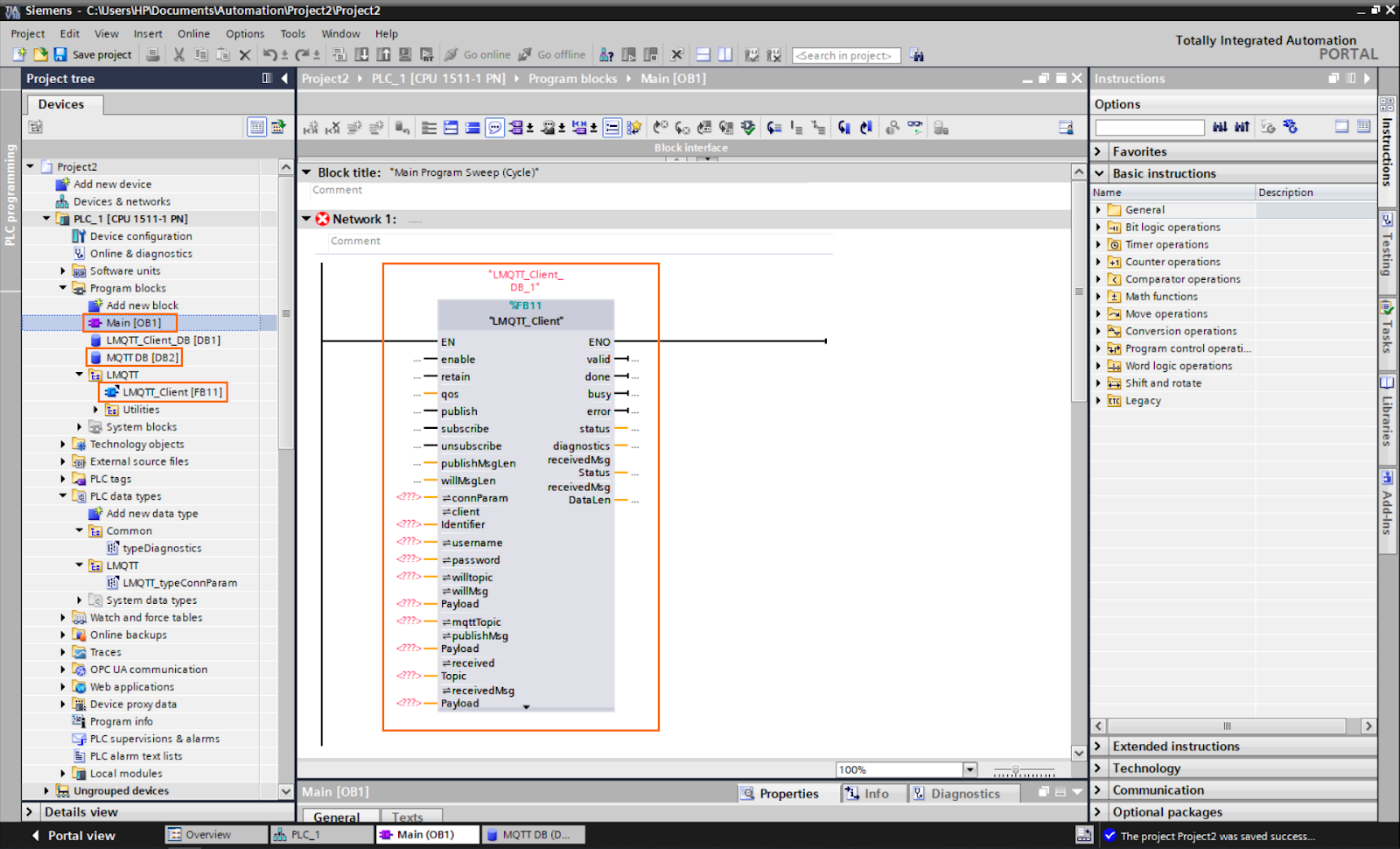
As you can see, this block has many inputs and outputs. We need to create a tag for each one. We will use a DB and create elements for each input/output with their adequate data type. Create a global DB named “MQTT DB” and create elements with their start values as follows.
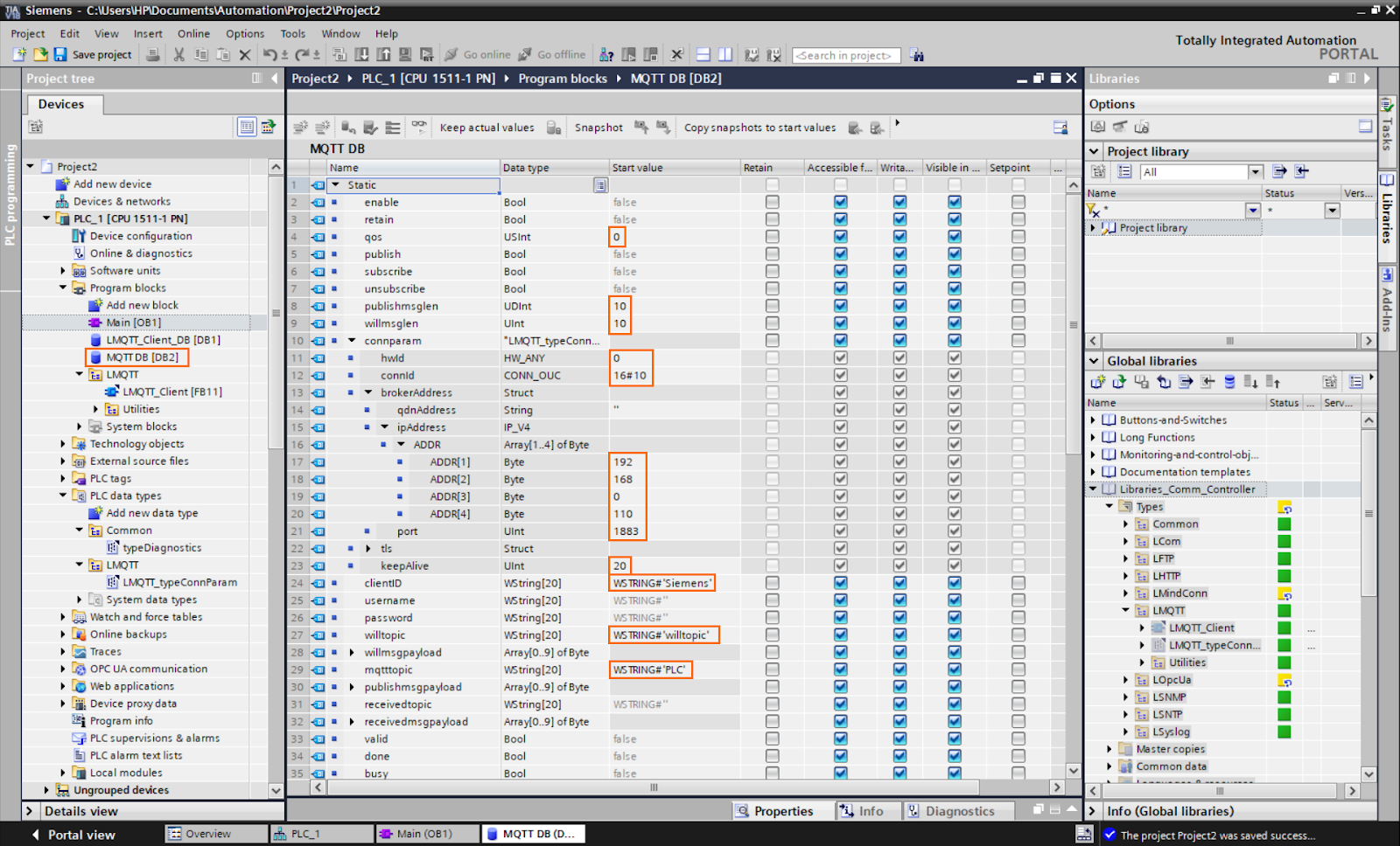
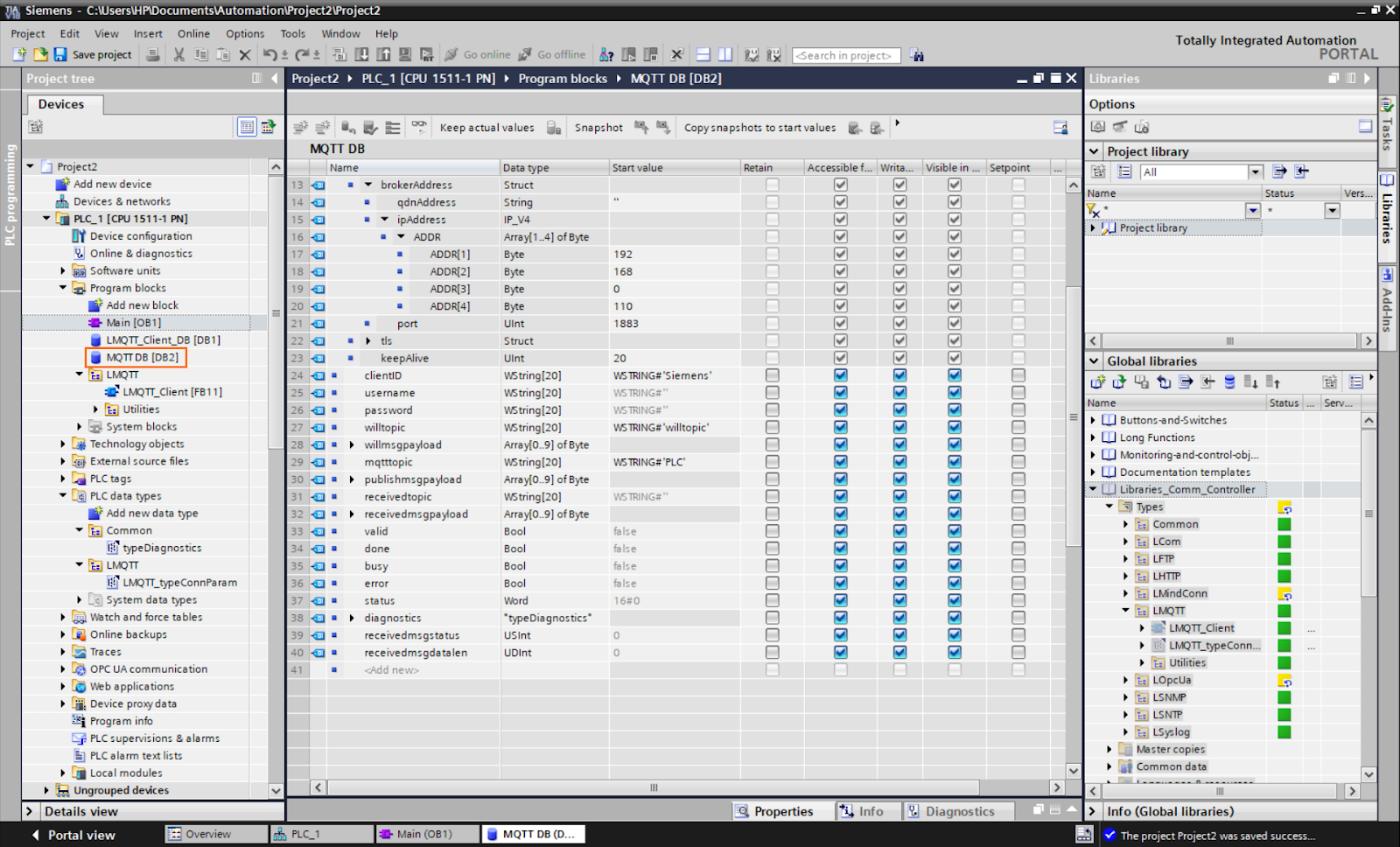
The highlighted values are mandatory. You must fill in each of these values . Otherwise, the block cannot work.
- QOS: Quality Of Service can have a value between 0 and 2.
- publishmsglen: Length of the published message.
- willmsglen: Length of the last will message.
- hwId: Hardware identifier. You can keep it at 0.
- connId: connection ID, must be unique.
- ADDR[1] to ADDR[4]: IP Address of the broker.
- keepalive: timeout timer.
- clientId: ID of the client in the MQTT communication.
- willtopic: Last will topic.
- mqtttopic: Current topic.
You can find more details about each input/output function in the official documentation.
Once done you should obtain a block similar to the following figure.

We are now done with the configuration of the TIA Portal side. We can test the communication.
MQTT communication demonstration
To interact with the communication elements, we will use a watch table to change the value of the inputs and monitor outputs. Add the following elements to a watch table.

- enable: Input boolean that enables the communication.
- publish: Input boolean that publishes the data in the publish payload.
- subscribe: Input boolean that subscribes to the topic specified in mqtttopic.
- unsubscribe: Input boolean that
- valid: Output boolean that indicates the connection validity.
- status: Word containing a status code of the communication (16#7004 = connection established).
- mqtttopic: Publishing and subscribing topic.
- receivedtopic: Received topic.
- publishmsgpayload[0]: First element of the sent payload.
- receivedmsgpayload[0]: First element of the received payload.
When “enable” turns to 1, the communication starts. If the connection is established successfully, the “valid” boolean turns to 1, and we should find the value 16#7004 in the status word. Then, we can use the “publish” boolean to publish the data in the published payload into the broker. Or the “subscribe” boolean to subscribe from the broker through the subscribe payload.
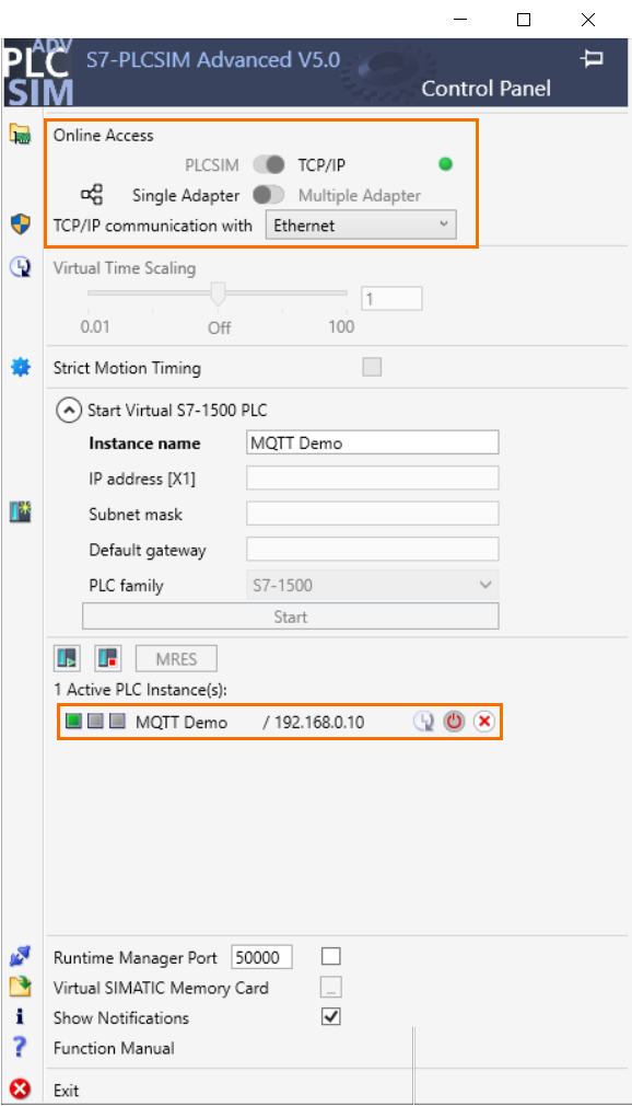
To test the communication on the PLC side, we will use a PLCSim Advanced instance configured with the same IP address as the CPU and with the TCP/IP virtual adapter enabled. Create the virtual PLC instance and load the program into it.
Now we can start the visualization in the watch table and observe what happens whe turn the inputs to 1.
Here we change the value of “enable” to 1. The “valid” boolean turns to 1 and the status word contains the 16#7004 value. This means the MQTT communication between the PLC and the broker has been established. Also, the Node-RED MQTT nodes indicate “connected, " meaning that the MQTT connection has been established between Node-RED and the broker.
Now let’s try to publish data. The publish payload contains the 198 value. When changing the state of “publish” to 1, it sends the data to the broker which relays it to Node-RED (subscribed to the “PLC” topic). We can see it appearing in the Node-RED debug console.
For last, we can try to subscribe to receive data. When we change the value of “subscribe” to 1, we subscribe to the “PLC” topic. If inject data (publish) in the Node-RED side, we receive it in the received payload.
Conclusion
In this tutorial, you learned how to establish MQTT communication between a Siemens PLC and Node-RED using the TIA Portal and the Mosquitto broker. The tutorial guided you through the setup of the Mosquitto broker on the Mosquitto/Node-RED side, enabling communication between the PLC and Node-RED. You saw how to use Node-RED to publish and subscribe to data via the Mosquitto broker and how to integrate the LMQTT library provided by Siemens into the TIA Portal project. Note that you can use various protocols in Node-Red - Ex: RS-232
MQTT is one of the easiest protocols to implement in industrial automation, thanks to its efficient subscribe/publish system. The use of a central broker for communication between devices simplifies the integration process, making MQTT highly scalable and flexible. Additionally, the LMQTT library provides ready-to-use communication functions in the Siemens environment, streamlining the implementation of MQTT communication with Siemens PLCs. Furthermore, Node-RED's intuitive and user-friendly visual interface adds to the ease of implementation. With its drag-and-drop functionality and a vast library of pre-built nodes, Node-RED allows automation engineers to create complex communication flows effortlessly. Combining the power of MQTT and Node-RED in the Siemens environment, automation engineers can easily design, deploy, and manage robust communication solutions, making industrial automation more accessible and efficient
