S7-1200 PLC Configuration - CPU Digital IO Settings

Introduction
S7-1200 is considered one of the family members of the new Siemens Step7 series of PLCs, which can work in small and medium-sized industrial processes. This PLC has replaced the S7-200 model by providing more features.
To program the S7-1200 PLC, first, it is necessary to configure the hardware in the software environment (TIA Portal) and, after that, start programming. The purpose of hardware configuration is to introduce the modules used in the PLC and apply appropriate settings.
Prerequisites
What you will need to follow along with this tutorial is the installation of TIA Portal software on your computer. The TIA Portal version 16 will be utilized in this tutorial; however other TIA Portal versions are also acceptable.
Creating a New Project and Selecting PLC Hardware
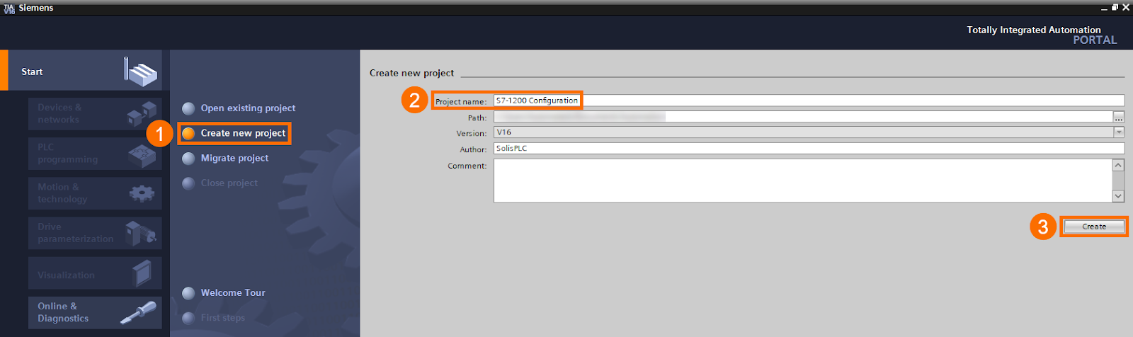
The first step for PLC programming in the TIA Portal software is to create a new project and select the desired hardware model. For example, you can name the new project "S7-1200 Configuration" and press the "Create" button.
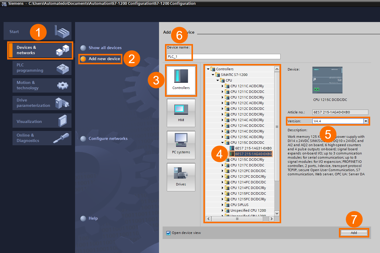
Under the "Devices & networks" tab, click "Add new device" to open the "Controllers" section. Then under the "CPU" folder of "SIMATIC S7-1200", choose "CPU 1215C DC/DC/DC" with the article (serial) number "6ES7 215-1AG40-0XB0". Select the version of your controller (in this case, version 4.4), give your device a desired name, such as "PLC_1", and then press the "Add" button.
After selecting the desired CPU, the environment of the hardware configuration section is displayed in the TIA Portal software. At this point, you should configure the processor before switching to other configuration steps.
CPU Communication Setting
Double-click on the CPU graphic in the "Device View" tab to open the inspector window. Under the "Profinet interface [X1]" item, select "Ethernet addresses" so that you can set the desired IP address in the IP protocol section.
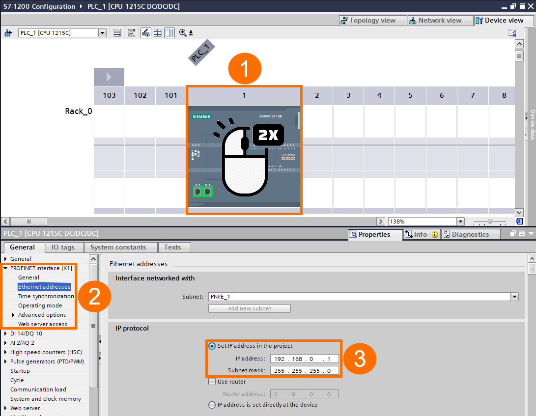
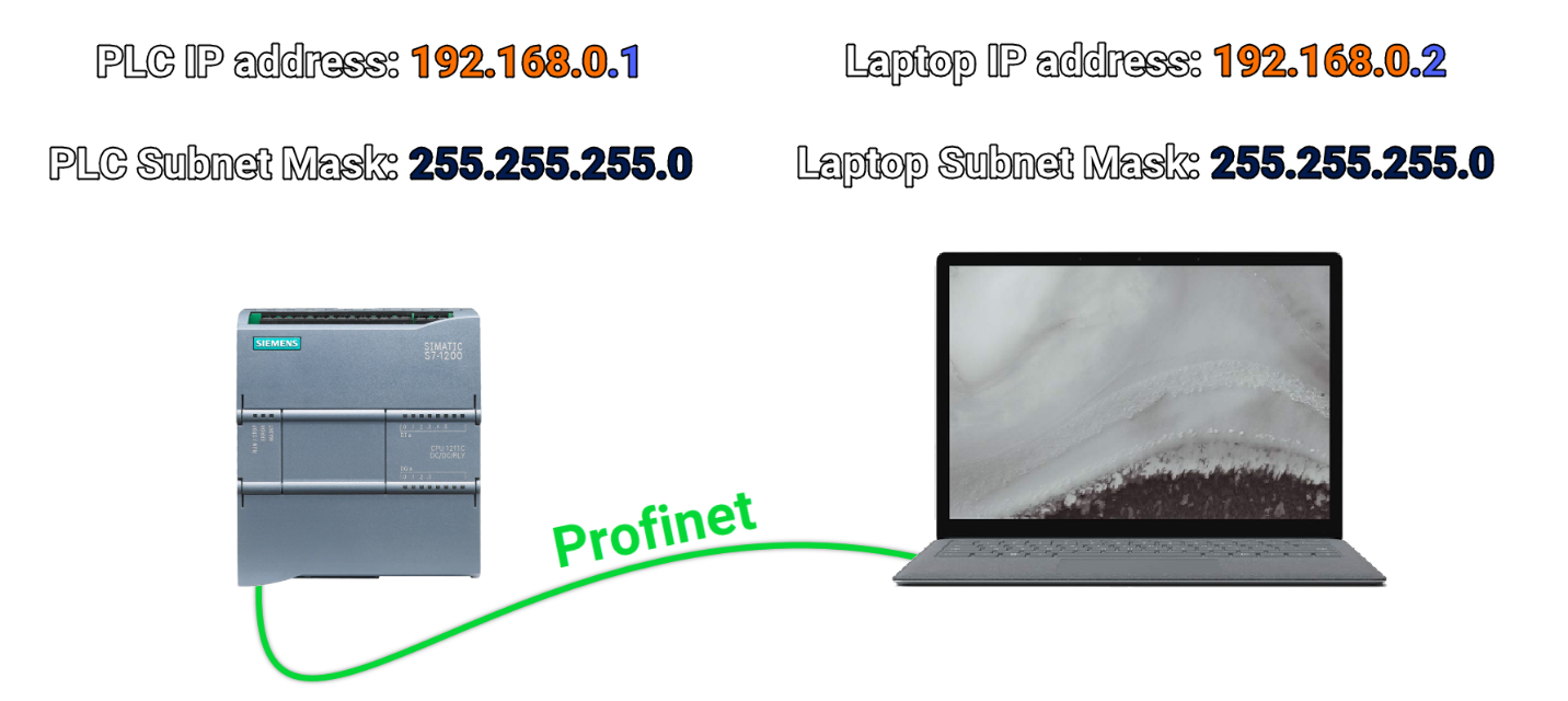
In setting the IP address, consider that the dedicated address given to the CPU should be unique, meaning it has not been used before by another device in the network. Also, the IP class of the PLC must be the same as the IP class of other equipment intended for communication, including the programming computer. It means that the first three parts of the IP from left to right are the same in both devices, but the last part of the IP is different. Also, the "Subnet mask" should be the same on both devices.
CPU Inputs and Outputs
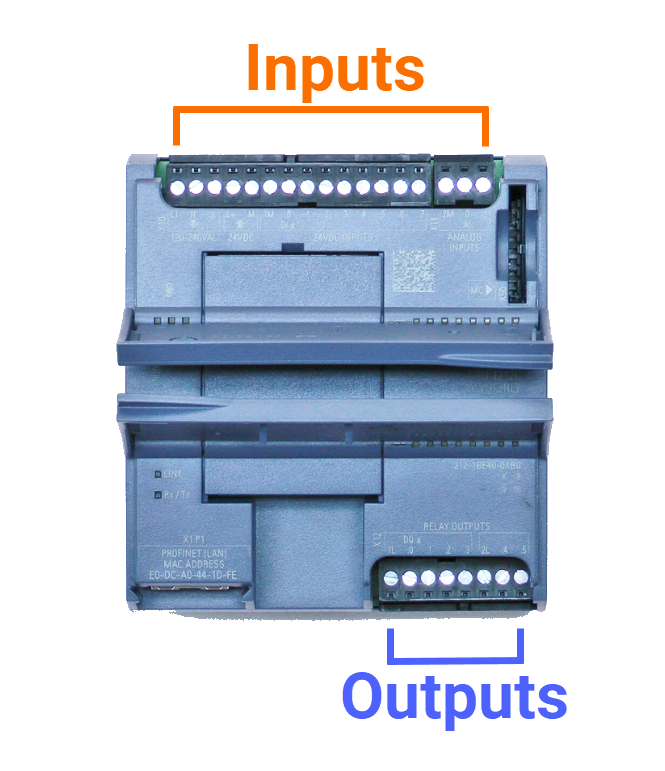
All S7-1200 CPUs are presented in a compact form, so they have several input and output terminals, whose settings can also be done in the CPU settings section. Note that the number and variety of inputs and outputs of each CPU may differ from other CPUs. Here, the settings based on the selected CPU in this tutorial are described.
CPU Digital Input Settings
Expand the "DI 14/DQ 10" in the inspector window and select the "Digital inputs" item. The settings that can be applied in this section are:
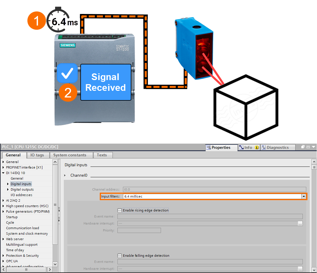
Input filters: Here, you can choose a number in milliseconds as the DI signal filter time. The function of the filter is that the signal sent to the digital input terminal must be connected at least as long as the determined time in the Input filter section so it can be considered a logical signal.
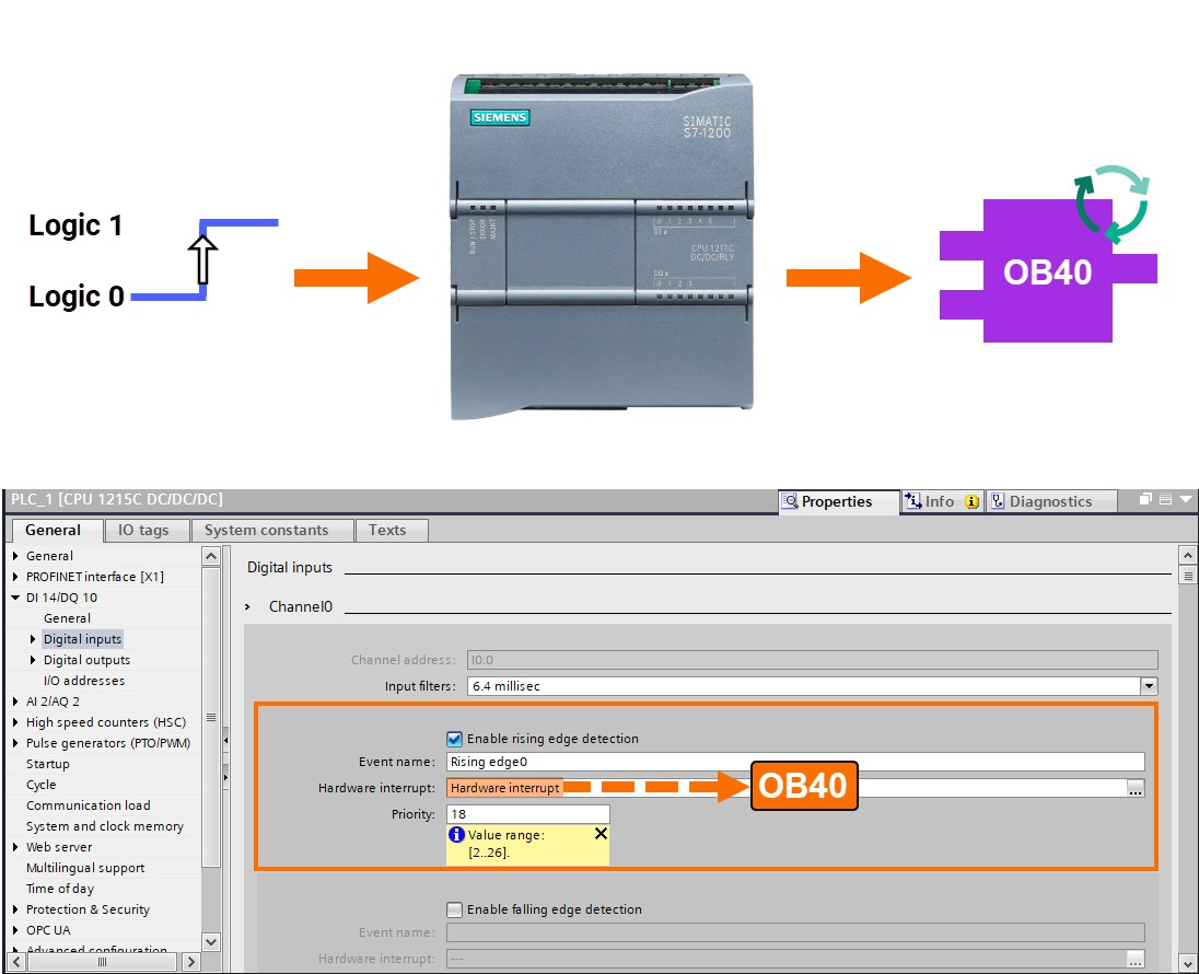
Enable rising edge detection: If you check the box for this option for a digital input channel, a hardware interrupt is activated and called by the CPU, provided that the rising edge signal is detected at the said channel. For this purpose, it is necessary to assign one of the hardware interrupt OBs (such as "OB40") to the desired channel and select it in the "Hardware interrupt" section. If the above settings are done correctly, whenever the digital input channel detects the rising edge signal, the "OB40" will be called by the CPU. In the "Priority" section, you can also set the priority of hardware interrupt execution.
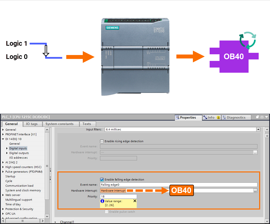
Enable falling edge detection: All the explanations in the case of "Enable rising edge detection" are also valid for "Enable falling edge detection", with the difference that the falling edge signal should be detected at the said channel.
CPU Digital Output Settings
This time under the "DI 14/DQ 10" in the inspector window, select "Digital outputs" to display its section. The settings that can be applied here are:
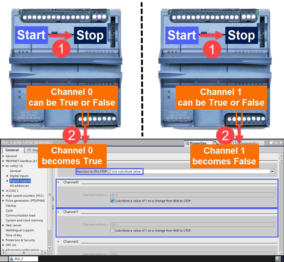
Reaction to CPU Stop: In this section, the digital output terminals' behavior can be adjusted when switching the CPU into stop mode. By selecting the "Use substitute value" option, you can change the value sent by each channel separately. For this purpose, in the settings section of each channel, when "Substitute a value of 1 ..." is activated, if the CPU stops, a logic value of one is placed in the digital output channel, and in other words, the desired digital output becomes "True". If "Substitute a value of 1 ..." is disabled, when the CPU stops, a logical zero data is placed in the digital output channel, and in other words, the desired digital output becomes "False".
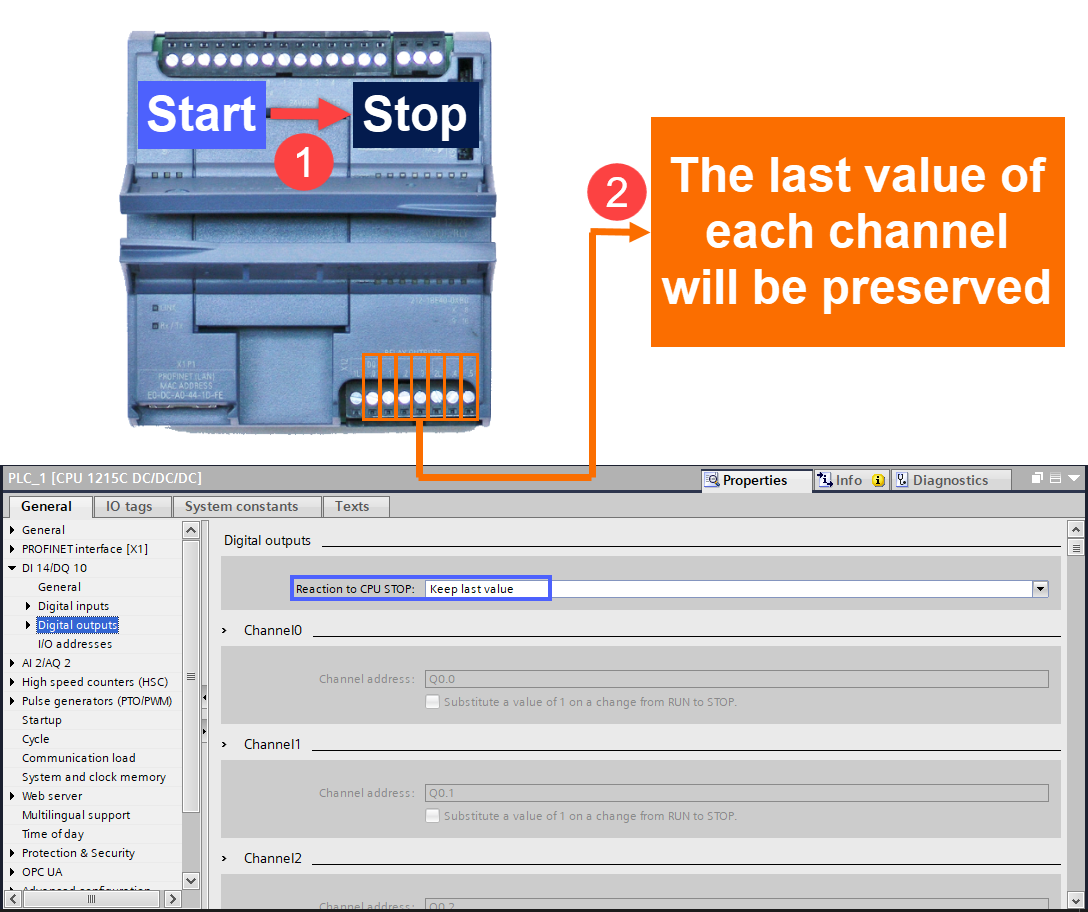
If the "Keep last value" option is selected in the section "Reaction to CPU STOP", when the CPU stops, the last value applied to each channel of the digital output terminal will be preserved for that channel. The use of this option should be done with great care and study.
CPU I/O Addresses Settings
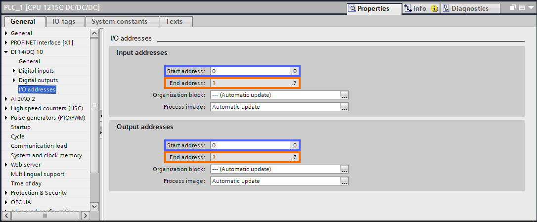
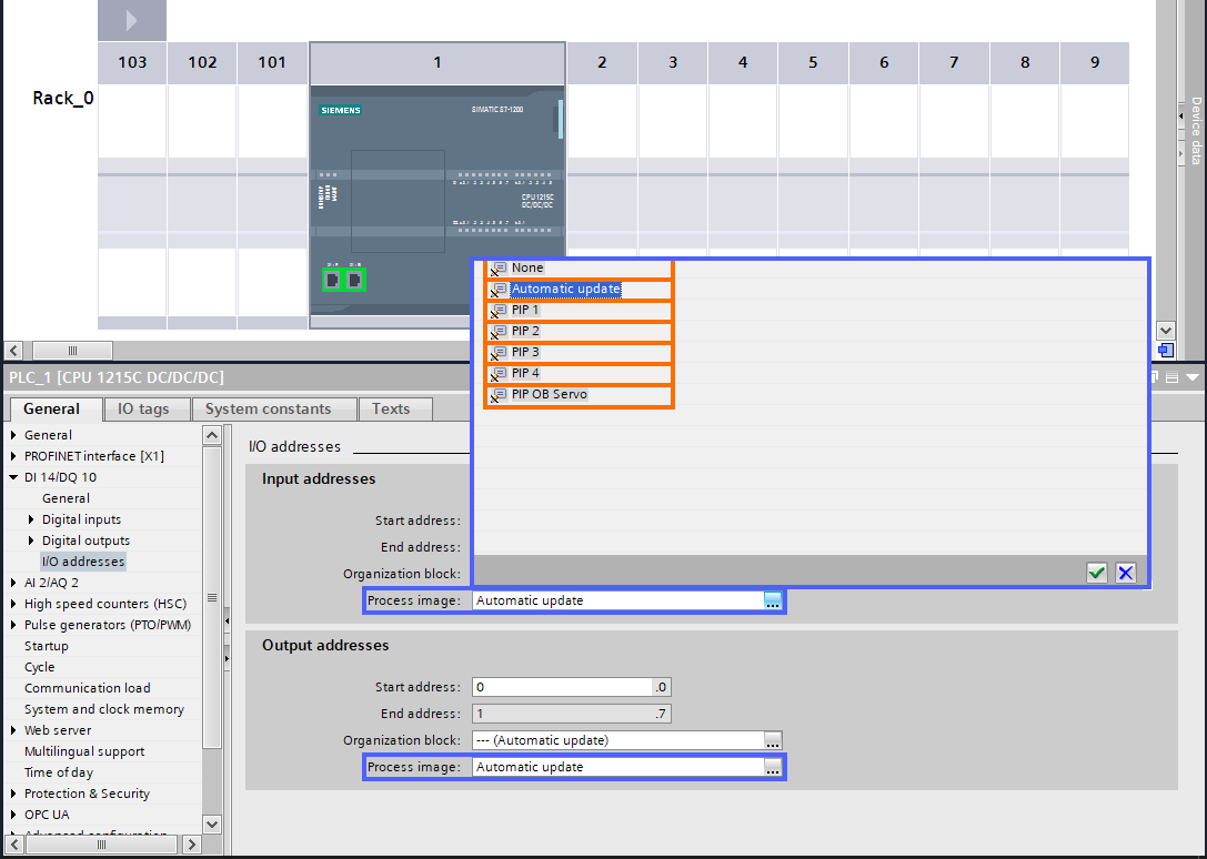
Now, under the "DI 14/DQ 10" in the inspector window, select "I/O addresses" to set the addresses of the digital inputs and outputs of this CPU. The settings that can be applied here are the followings:
- In the "Start address" section, you can specify the starting byte address of the module.
- In the "End address" section, you can see the end byte address of the module.
- In the "Organization block" section, it is possible to specify according to the work cycle of which OB the "Process image" should be updated. In this section, if the "Automatic update" option is selected, the CPU will update the "Process image" information once in each work cycle.
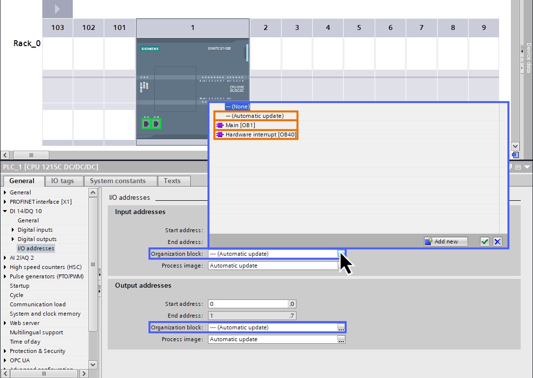
- In the "Process image" section, it is possible to specify in which part "PII" or "PIQ" the information received from the digital input terminal should be placed. In this section, if the "Automatic update" option is selected, the information about the module is placed in a part of the "Process image" area, which is updated once in each work cycle.
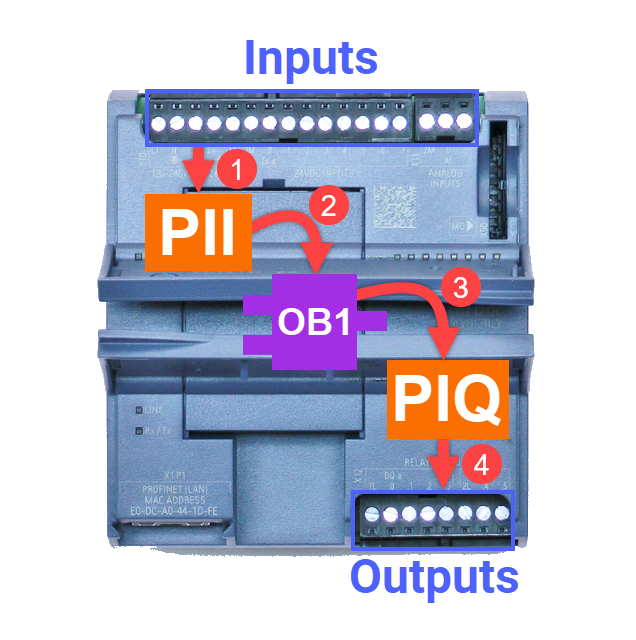
"PII" stands for "Process Image Input" and is the area related to input information in the CPU memory. "PIQ" stands for "Process Image Output" and is the area related to output information in the CPU memory.
The CPU reads the information of the input terminals once in each work cycle and places it in the "PII" area. Then it executes the program and puts the results in the "PIQ" area. And at the end of the work cycle, the "PIQ" information is sent to the digital output terminals.
In normal conditions, there is no need to change the "Organization block" and "Process image" options. So, keep the "Automatic update" command for both of them.
Conclusion
This tutorial discussed how to start configuring S7-1200 CPU as one of the new Siemens Step7 series of PLCs. You learned how to create a new project to add your desired hardware model to the TIA Portal software. You learned how to adjust settings for the CPU so it can communicate with other equipment in the network.
You understood the embedded input and output terminals settings of the S7-1200 can also be done in the CPU settings section. The features that can be applied in the CPU digital input section are input filters and enabling rising or falling edge detections. The setting that can be adjusted in the CPU digital output section is the reaction to the CPU stops.
You learned how to specify the starting byte address of the module to see what the end byte address will be. And finally, you understood it is possible to update the "Process image" based on the work cycle of your desired OB and how to determine in which part "PII" or "PIQ" the information received from the digital input terminal should be placed.
