S7 PLC to PLC Communication using GET/PUT Instructions in Siemens TIA Portal

Introduction
It is common to find multiple PLCs within a single installation in modern industry. It can be different parts of the process that interact with each other or redundant systems that ensure continuity of service. Data exchange between PLCs has become simple to implement thanks to fieldbuses which allow a reliable real-time connection.
Using this type of communication allows for example to order a second PLC to take over in case of failure or to synchronize different machines within a production line.
The latest S7 PLC families from Siemens (S7-1200 and S7-1500) inherently support the Profinet protocol. Therefore, its implementation within the Siemens environment is intuitive and requires a minimal number of steps.
In this tutorial, we will see how to configure a Profinet network between two S7 PLCs, and we will use the GET and PUT instructions in the first PLC to read and write data directly in the second one.
Prerequisites
To follow along with this tutorial, you will need an installation of TIA Portal. We will be using TIA Portal v17, but you can use any other version. No additional hardware or software is required.
Configuring the Profinet network in TIA Portal
To set communication between two Siemens PLCs, we need to create and configure a Profinet network between the two PLCs.
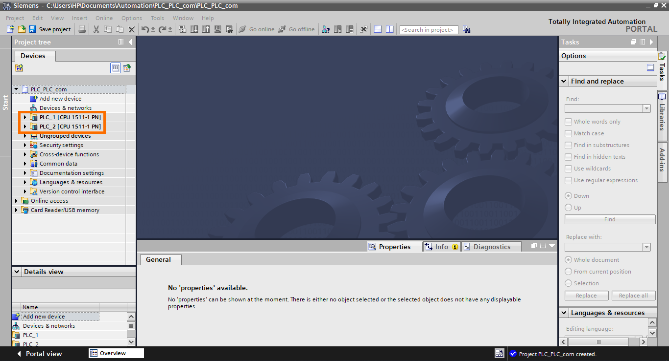
Create a new project in TIA Portal and add two PLCs. You can choose any CPUs that support Profinet.
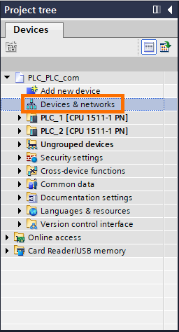
Then, open the network view by double-clicking on “Devices & networks” in the Project tree.
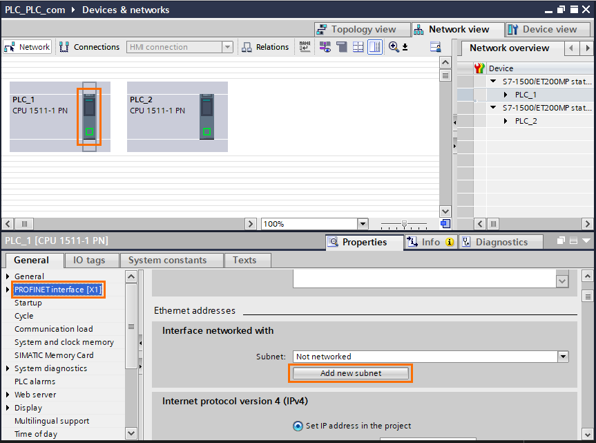
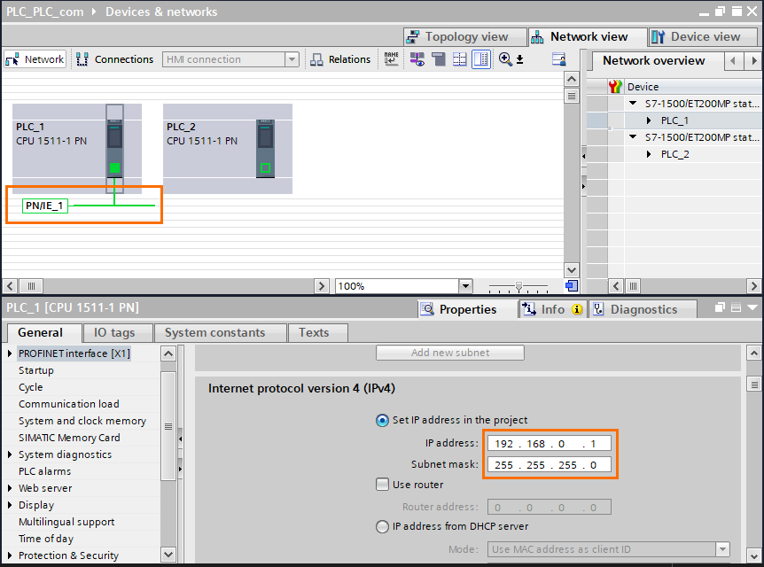
In the network view, select the first CPU (PLC_1), then select “PROFINET interface” and click on “Add new subnet” to create a Profinet network.
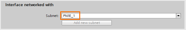
You can see that a new subnet has been created called “PN/IE_1”.
Scroll down to find the IPv4 section. The default IP address of the PLC is {192.168.0.1/255.255.255.0}. You can keep the default address or set a new address. We will be using the default one.
You can see that a network (PN/IE_1) has been created.
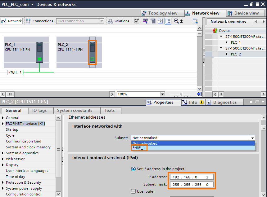
Select the second CPU (PLC_2) and select “PN/IE_1” as the network interface. The default IP address has been set on the second available address which is {192.168.0.2/255.255.255.0}
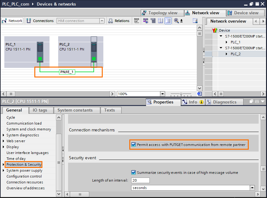
Since we will use the PUT and GET instructions to access data of PLC_2, we need to allow them in the second CPU (Siemens disables them by default for security purposes). Open the “Protection & Security” tab and check “Permit access with PUT/GET communication from the remote partner.”
Notice that now both CPUs are linked to the same network.
Using the GET and PUT instructions in TIA Portal
The GET and PUT instructions are used to read or write data from another remote S7 PLC. The GET instruction reads data from the desired data area of the second PLC and assigns them to the data area of your choice in the first PLC. Same thing for the PUT instruction but for writing data instead.
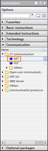
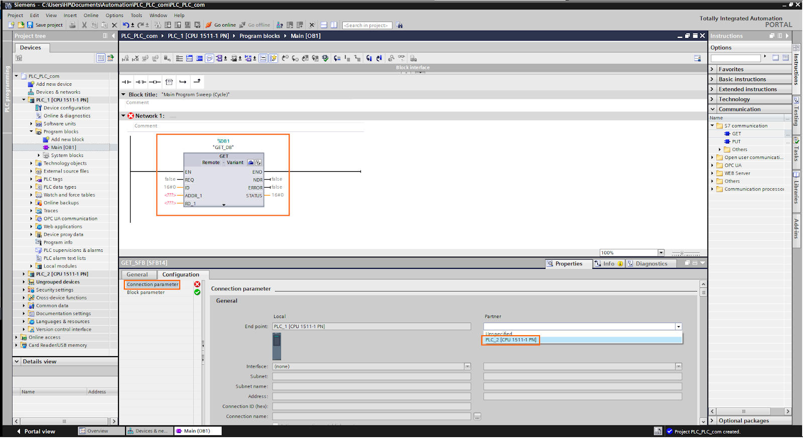
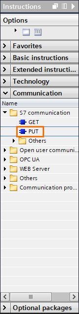
Open the main program (OB1) of the first PLC then, on the instructions list, open the “S7 communication” folder and drag and drop a GET instruction in the first network.
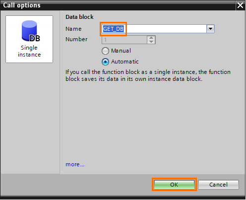
After dropping the instruction, a “Call options” will appear asking you to create a DB for the GET instruction. Keep the default name “GET_DB” and click on “OK.”
Once the instruction is added, click on “Connection parameter,” then select “PLC_2” as the connexion partner.
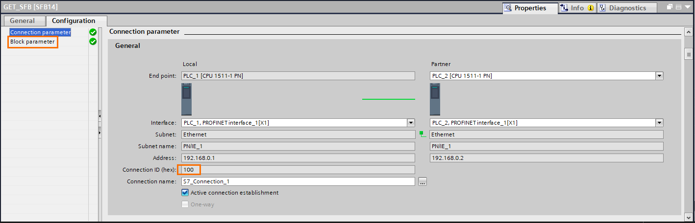
You can notice that the Profinet ID has been automatically added to the instruction (100). Then, click on “Block parameter” to set the instruction’s parameters.
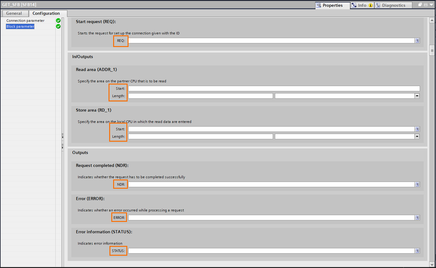
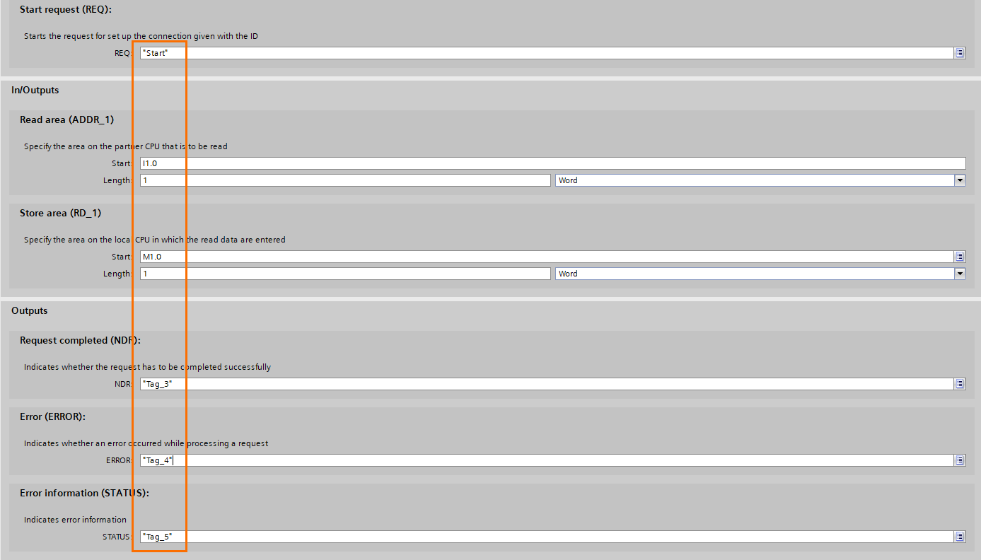
The GET instruction parameters are:
- REQ: Starts the instruction on detecting a positive edge. You can use any boolean you want.
- ADDR_1: Select the memory area you want to read in the second PLC.
- RD_1: Defines the memory area where you want to store the read data from the second PLC.
- NDR: Is a boolean output set to 1 once the operation is done.
- ERROR: Is a boolean output set to 1 if an error occurred during the operation.
- STATUS: contains an INT that gives information about the status of the operation.
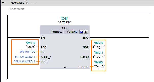
We will read one word starting from I 1.0 (IW1) in the second PLC and store them in a word starting from M 1.0 (MW1) in the first PLC. Then, you can set the tags you want in the other parameters.
Once all parameters are set, they will be automatically added to the instruction.
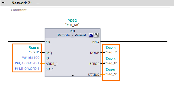
You can redo these last steps to add and configure a PUT instruction.
For this instruction, we will write the data contained in the word starting from M 1.0 (MW1) in words starting from Q 1.0 (QW1) in the second PLC.
Conclusion
In this tutorial, you learned how to create a network between two S7 PLCs and access data directly from the first one.
The Siemens environment allows its users to establish communications between S7 PLCs without programming both parties. Instead, we can simply directly access the data of the desired PLC simply by using the GET and PUT instructions dedicated to this purpose.
