Siemens PLC Control of Motor Speed Through a Drive Using Telegram 1

Introduction
SINAMICS S200 PN is one of the Siemens servo drive systems that offers essential speed control capabilities as part of its core functionality.
This tutorial covers the crucial steps in configuring speed control using a GSDML file with one of the Siemens SIMATIC controllers, the S7-1500 PLC. Get ready to delve into the specifics of two scenarios: basic and function block controls, with detailed descriptions.
When using SINAMICS S200 PN in speed mode, you can rely on its seamless support for the 'standard telegram 1', which will be discussed in this tutorial. The 'standard telegram 1' is exclusively designed for use in the RT (real-time) mode.
Prerequisites
What you will need to follow along with this tutorial:
- You need to install the TIA Portal software on your personal computer. Although this tutorial refers to version 18, rest assured that other versions of the TIA Portal will work just fine.
- You need to be familiar with servo motor commissioning.
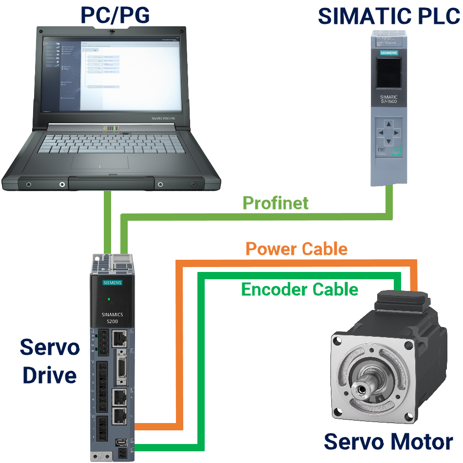
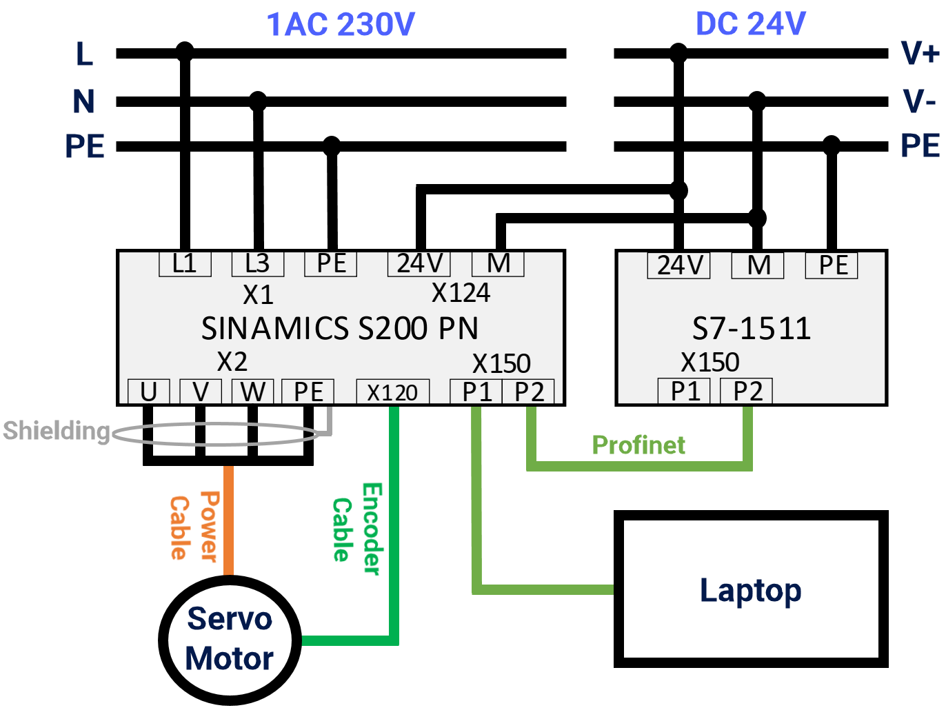
Wiring the Hardware
In this setup, the servo drive system runs on a single-phase AC230V power supply, while the SIMATIC system relies on a power supply of DC24V. Keep in mind the significance of checking the power supply voltage. Don't underestimate the consequences of getting the wiring wrong—it can harm the drive or controller. Observe Figure 2.1 to understand how the hardware is configured in this application.
Installing GSDML File
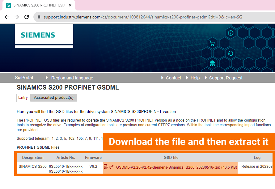
Let's explore the steps involved in installing the GSDML file into Siemens TIA Portal software. Access the GSDML file for SINAMICS S200 PN by downloading it from here. Extract the contents of the zip file.
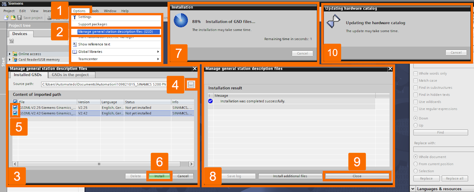
Launch the TIA Portal software, switch to Project View, click on the Options menu, and select the option to Manage general station description files (GSD). Choose the source path folder by clicking the corresponding button. Pick the desired GSDML file/files for the installation process. Click on the Install button to initiate the installation of the GSDML file/files. You'll see the installation status displayed in the TIA Portal. Once the installation is complete, press the Close button to dismiss the pop-up screen. Finally, the software starts updating the hardware catalog.
Configuration of the Hardware
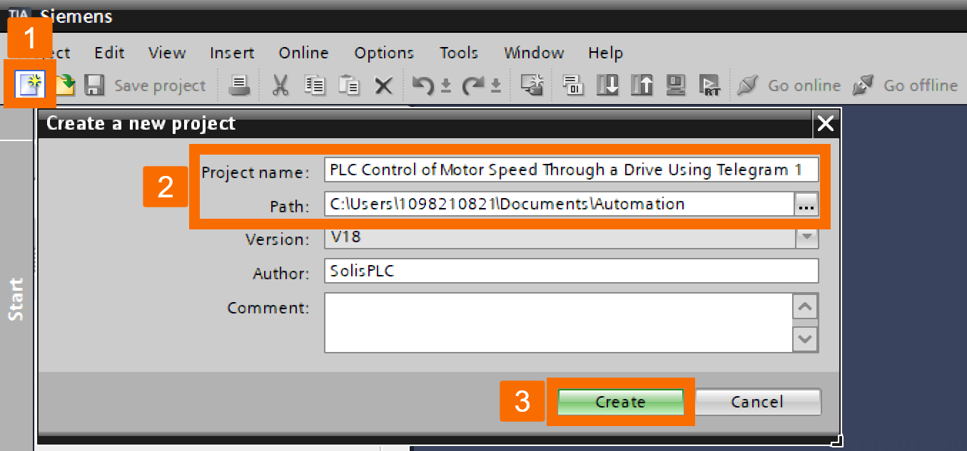
It's time to discover how to set up the corresponding TIA Portal project and configure the S200 PN drive using standard telegram 1. With TIA Portal software still up and running, let's get busy creating a new TIA Portal project and setting the project name and path according to your preferences.
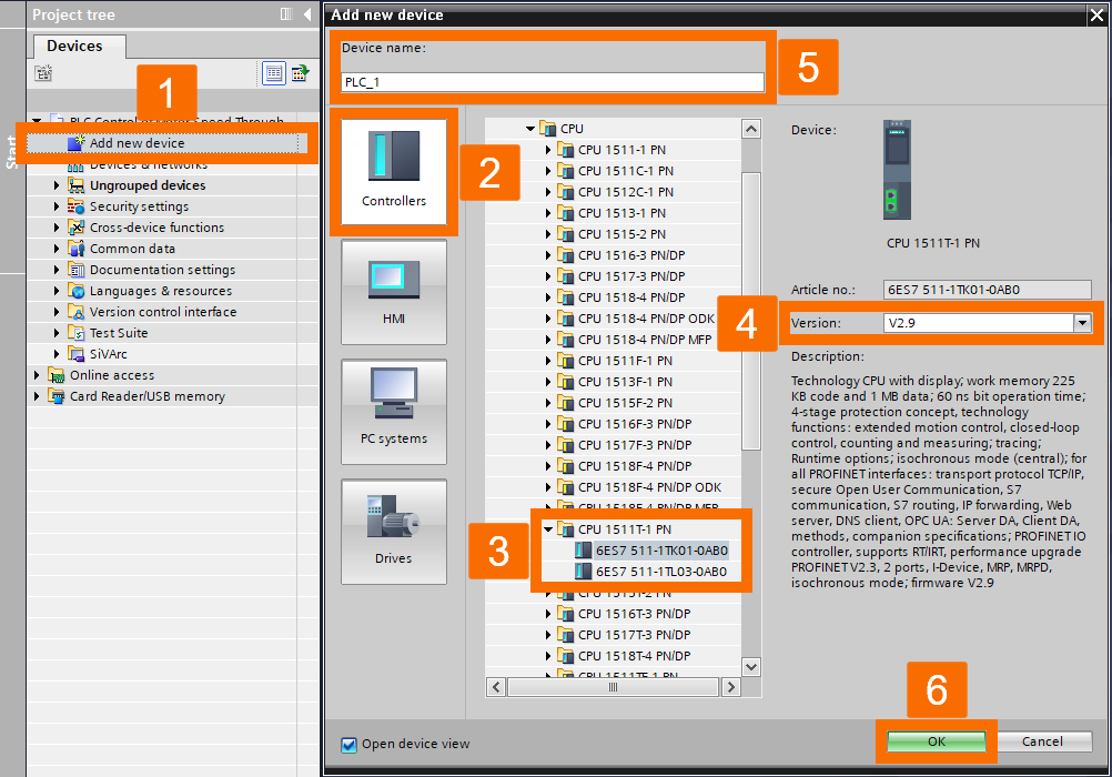
Next, double-click over the Add new device to get the CPU added to the project. Select the Controllers category. In the Controllers list, find the CPU 1511T-1 PN you want to use. Once you've got it, take a quick look to confirm the firmware version of the CPU. Feel free to modify the device name of the CPU according to your preference. Tap on the OK button to officially include the CPU in the project.
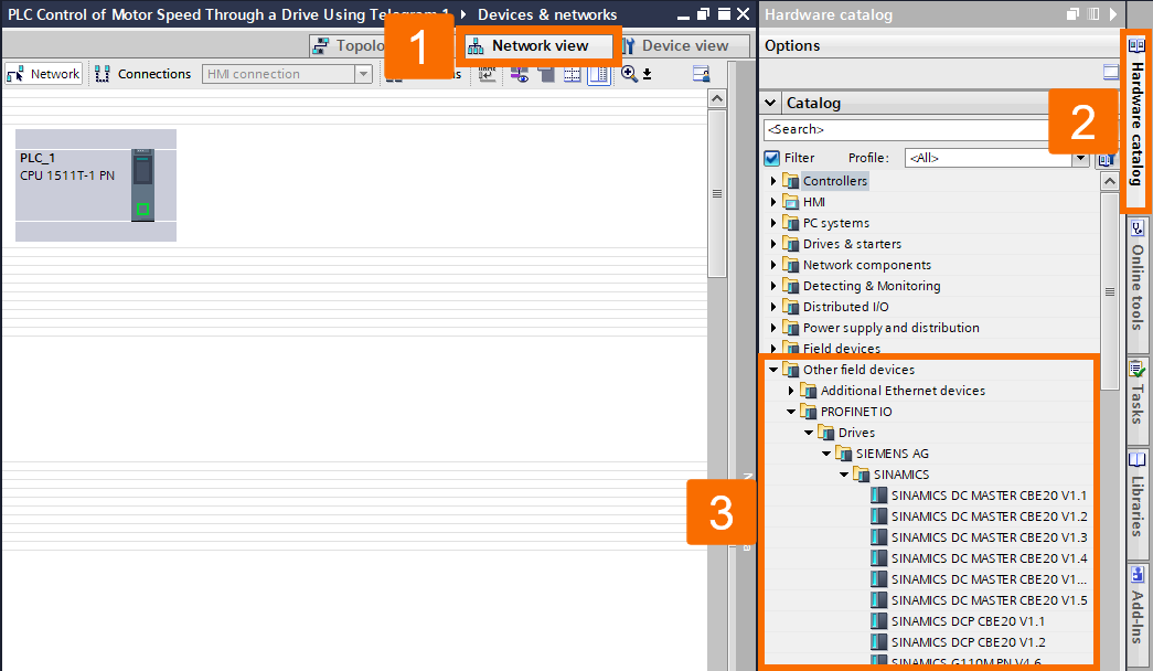
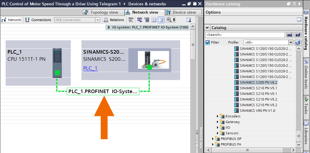
Once the Device configuration window opens, flip to the Network view tab. Open up the Hardware catalog. You've got to go through the folders and find your way to SINAMICS under Other field devices -> PROFINET IO -> Drives -> SIEMENS AG.
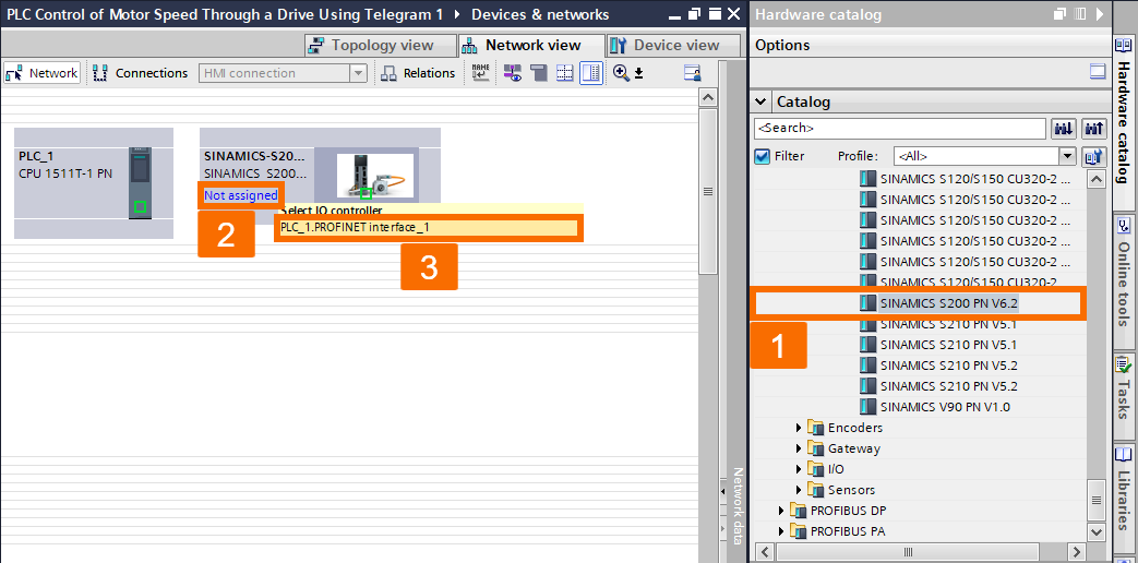
Locate the GSD file labeled SINAMICS S200 PN V6.2 and double-click on it to include this servo drive in the project. Click on the link labeled Not assigned in the S200 PN drive. Pick the 'PLC_1.PROFINET interface_1' as the IO controller you're aiming for.
Once you've linked the IO controller to the drive, you will witness the Profinet communication network displayed, just like in Figure 4.5.
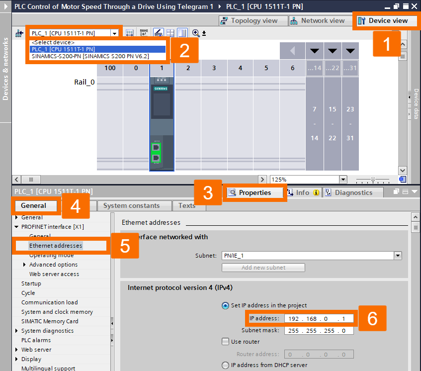
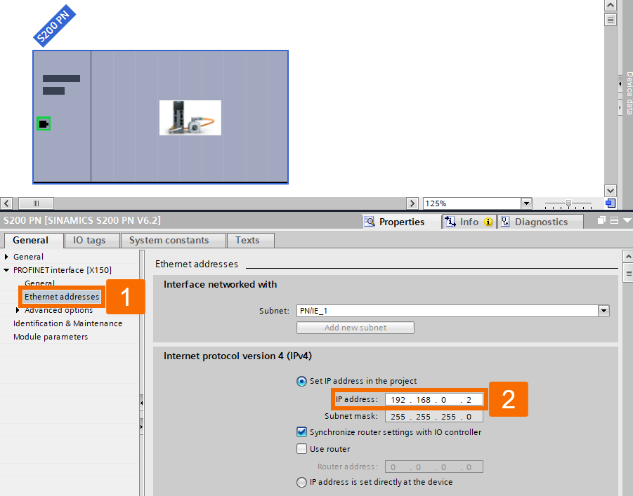
Go back to the Device view after being in the Network view. Pick out the PLC from the options in the dropdown menu. Go with the selection to view CPU properties. Pick the Ethernet addresses in the General properties list to make parameter modifications. Edit the IP address, but be cautious not to set a conflicting custom IP address with another device on this network.
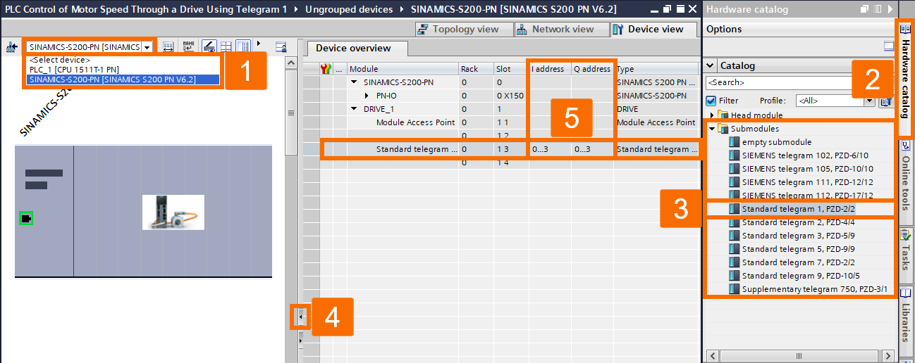
Click on the dropdown menu and choose the SINAMICS S200 PN Drive this time. Go with the option labeled Hardware catalog and click on it. Expand the folder containing the submodules. Choose the 'Standard telegram 1' and place it into the project by double-clicking. After inserting the telegram, you'll find it on the Device overview screen, and the IO address associated with it will be visible. The input and output addresses are both specified to have a length of 4 bytes. The initial input or output address can be customized by the user to accommodate their application.
Within the Device view of the S200 PN drive, open the Properties. Choose the General function from the options available in the General menu. The device name of this servo drive can be customized to align with the user's application. As an example, in this particular application, it has been changed to S200 PN. After modifying the device name, the newly adjusted name will appear.
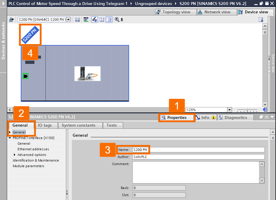
By opening the Ethernet addresses section, making modifications to the IP address is allowed.
PLC Control with the Move Instruction
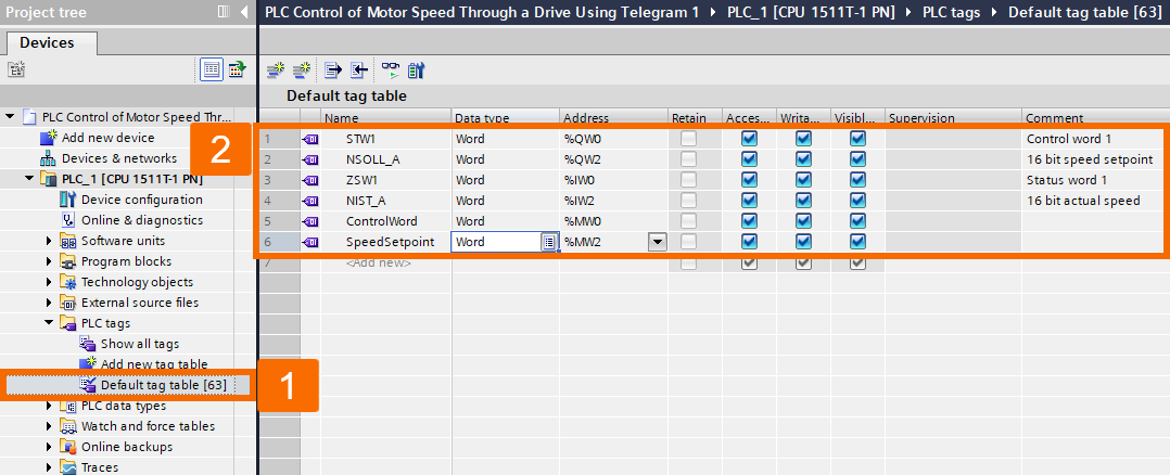
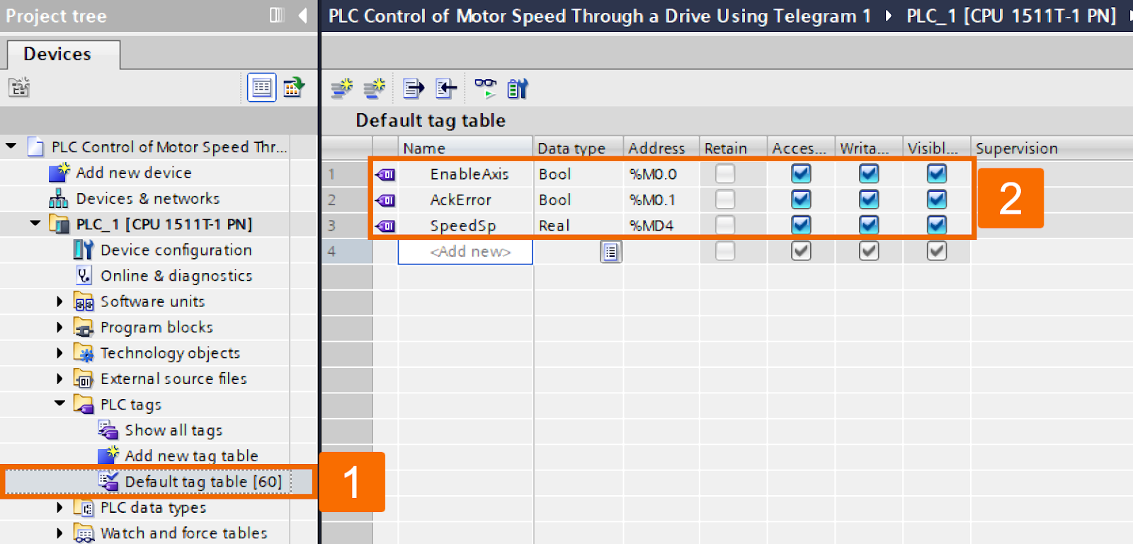
Get ready to understand how to use the MOVE instruction to take charge of the S200 PN systems. Access the Default tag table or create a new one under the PLC tags folder. Make the new PLC tags using the specific address highlighted in Figure 5.1. The input and output addresses should align precisely with the details provided in Figure 4.7 for the speed setpoint, control word, actual speed, and status word.
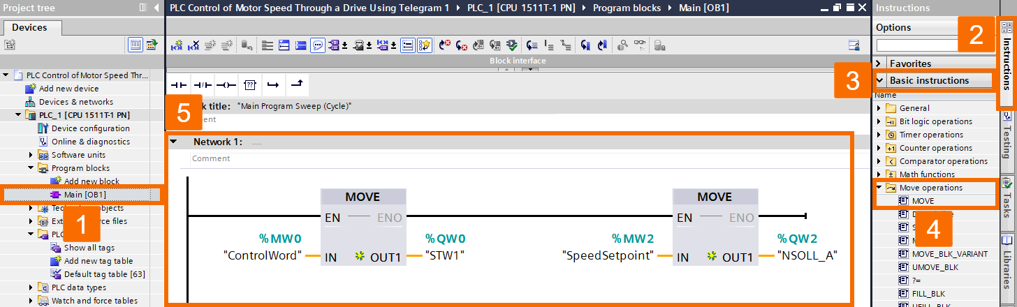
Locate the main Organization Block (OB1) under the Program Blocks folder and double-click on it to access it. Choose the Instructions task card. Drag the MOVE instruction from the Basic instructions -> Move operations folder and drop it onto network 1. Set up the programming logic according to the representation displayed in Figure 5.2.
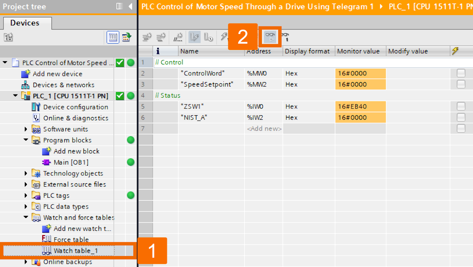
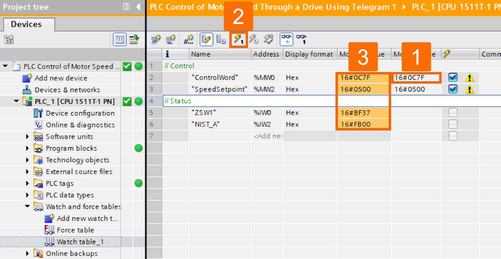
By double-clicking over the Add new watch table item, you can generate a new watch table named Watch table_1 and have it instantly open. Make modifications to the watch table by incorporating status monitoring and control operations, mirroring the configuration displayed in Figure 5.3.
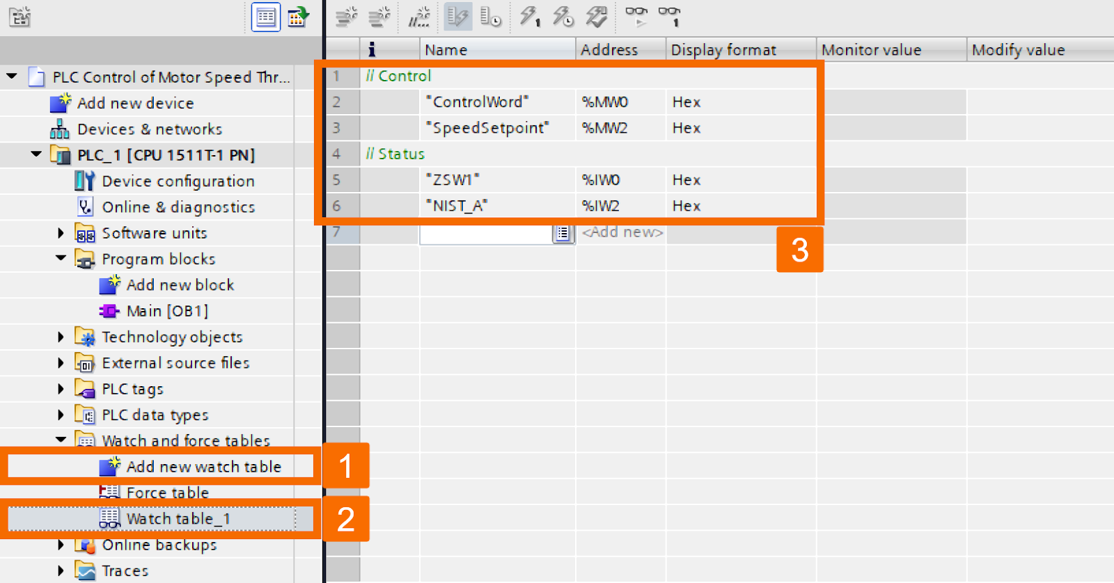
Figure 5.3: PLC control of motor speed through a drive using Telegram 1 -
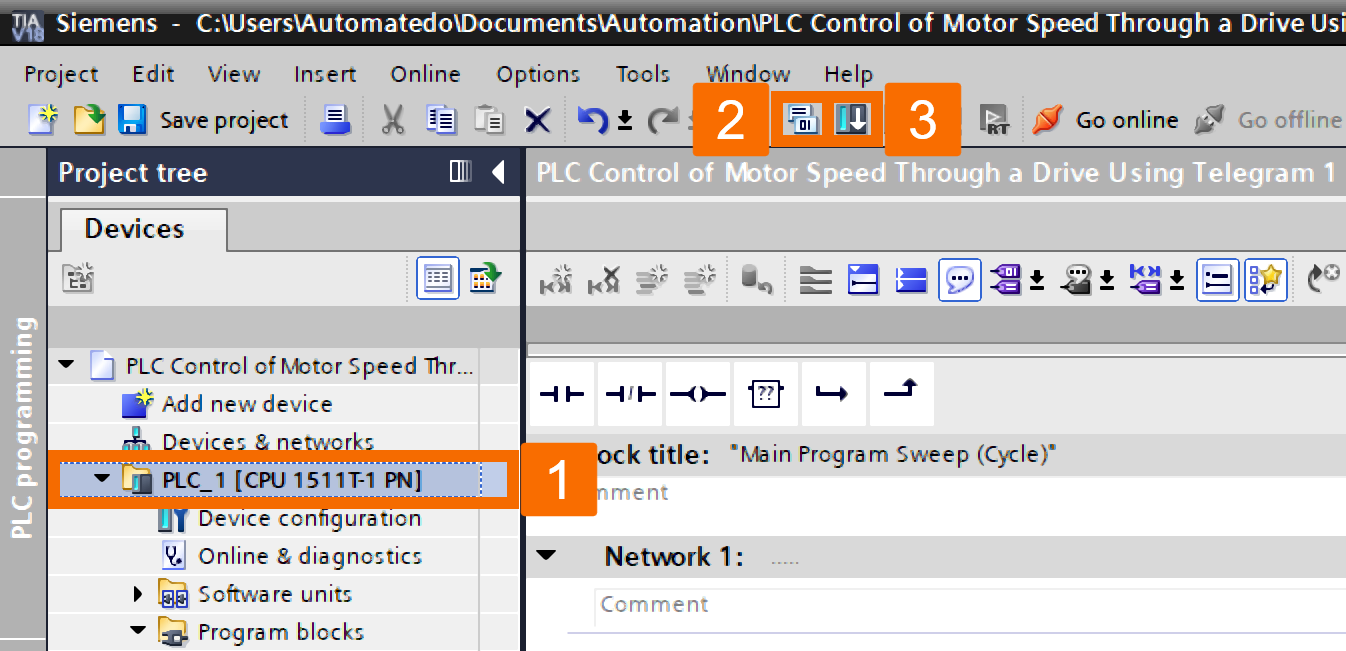
Select the PLC_1 folder, and proceed to compile the project and download it to the PLC by left-clicking their icons on the top toolbar.
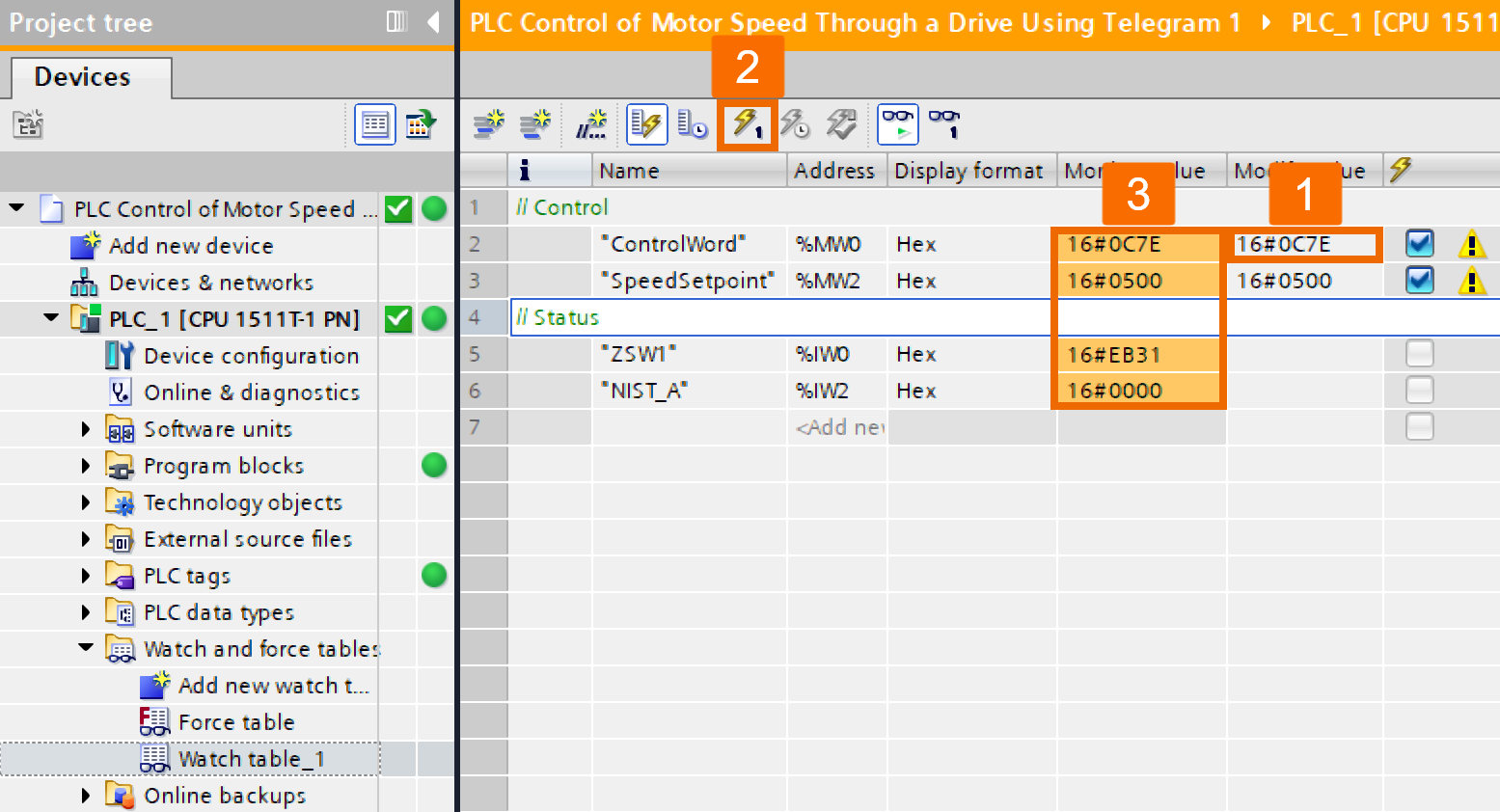
Access the Watch table_1 by double-clicking on it. Enable variable monitoring and forcing functionality by clicking the monitor button, represented by the eyeglasses icon.
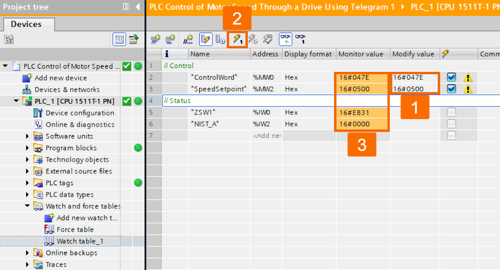
Customize the control word to the value of 16#047E and change the speed setpoint, setting it to 16#0500. Click on the Modify button to initiate value changes. Once you've adjusted the control, you will see the status of the drive reflecting the update. In the case of telegram 1, it's important to note that the speed setpoint serves as the reference setpoint, and the value 16#4000H corresponds to 100% of the reference speed in P2000.
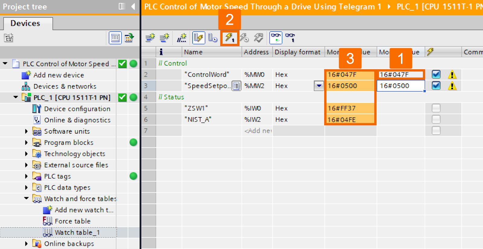
Activate the drive by changing the control word to the value of 16#047F and ensure monitoring of the status of the servo drive.
Switch the control word to the value of 16#047E to halt the servo drive and keep track of its situation for monitoring purposes.

Consider the necessary adjustments by modifying the control word to 16#0C7F to initiate the servo drive in the opposite direction and monitor its status accordingly.
Adjust the control word to the value of 16#0C7E or 16#047E to bring the servo drive to the stop mode, and remember to survey its status effectively.
PLC Control with the SinaSpeed Function Block
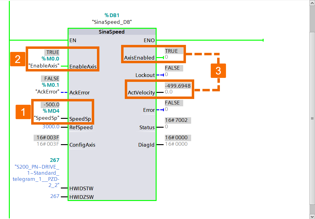
Let's explore how to utilize the SinaSpeed function block for smooth control of the S200 PN system like a pro. Go ahead and access the Default tag table or whip up a fresh tag table within the PLC tags folder. Start generating the PLC tags using the specified address displayed in Figure 6.1.
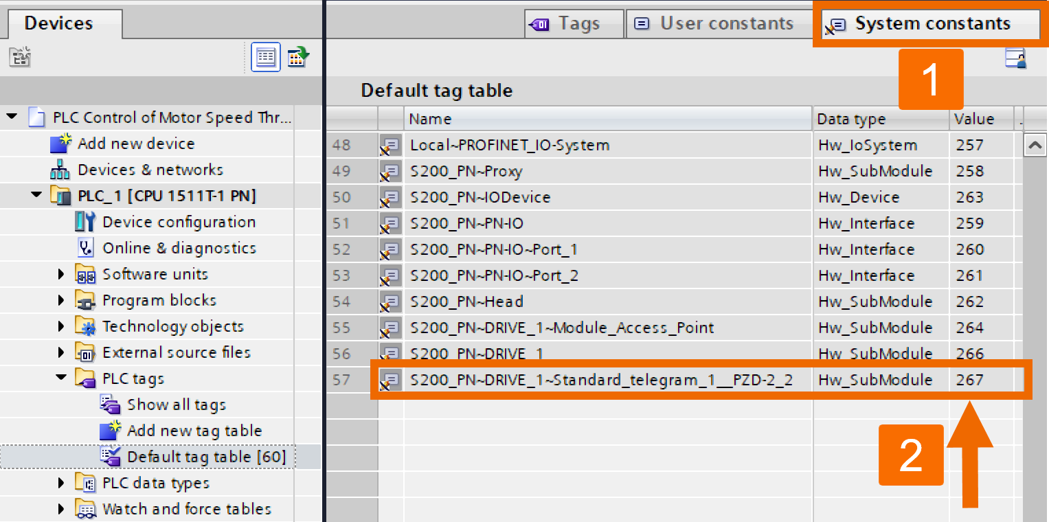
Within the Default tag table, jump over to the System constants view. Search for the target hardware identifier within the list and capture the value assigned to this constant variable.
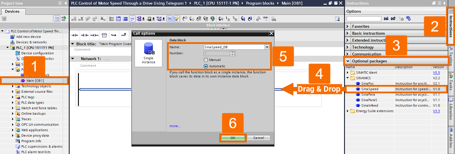
Locate the Main OB1 (Organization Block) within the Program Blocks folder and double-click on it. Select the Instructions task card. Grab the SinaSpeed instruction from the Optional packages folder and release it onto Network 1 using drag and drop action. Customize the name of the data block as per your preference, and you can let TIA Portal automatically assign the DB number or manually assign it yourself. Confirm the insertion of the function block to the project by pressing the OK button. This is a reminder that you can download the function block and its documentation from here.
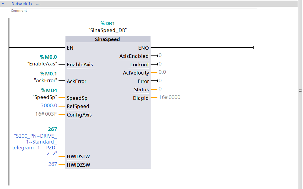
Implement the logic in your program based on the visual representation depicted in Figure 6.4. When dealing with the HWIDSTW or HWIDZSW, you can assign a constant variable name or directly allocate a constant variable value. Perform project compilation and then proceed to download it to the PLC.
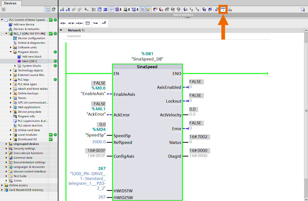
Activate the program logic monitoring mode by pressing the eyeglasses button.
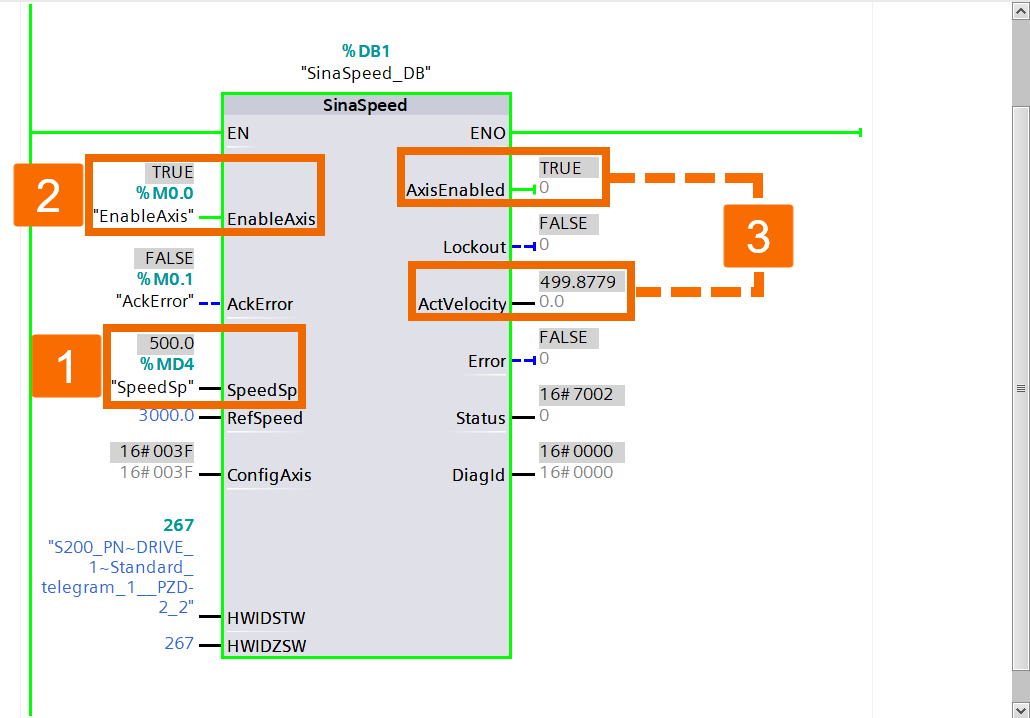
Adjust the speed setpoint value and activate the axis to initiate the drive.
Set the speed setpoint to a negative value, re-enable the axis, and observe the motor rotating in the opposite direction.
Conclusion
In conclusion, you learned about PLC control of motor speed through a servo drive using Telegram 1. You figured out how to establish the connection for this automation task and how to wire the hardware. You became acquainted with downloading and installing the GSDML file of your desired servo drive. You understood how to configure your hardware (PLC and servo drive) in TIA Portal. Finally, you grasped how to set up your PLC control using the Move instruction or implementing the SinaSpeed function block to observe the status of the motor speed.
