Siemens PLC Programming | Ladder Logic, HMI Development & Code Simulation

Introduction to Siemens TIA Portal PLC & HMI Programming
As we dive deeper into Siemens TIA Portal PLC & HMI programming, it’s essential to get our first “Hello World” program up and running on the virtual simulator for the PLC and HMI. As a recap, in the previous tutorial, we’ve built a TIA Portal project, added the hardware, and established communication to a live PLC.
This tutorial aims to explore “Program blocks” within TIA Portal, create a ladder logic program tied to two virtual inputs/outputs, and simulate the program on a PLC and HMI through TIA Portal.
Step 1 - Creating PLC Tags
Just as you would in RSLogix and Studio 5000, you must create the tags utilized on the PLC. TIA Portal makes it easy to segment the tags used for different purposes in separate tables. A new project will instantiate a base table called “Default tag table,” We’ll create the tags we need.
We will be creating four tags: PushButton1, PushButton2, LED1, and LED2. All tags are of Data type “Bool.”
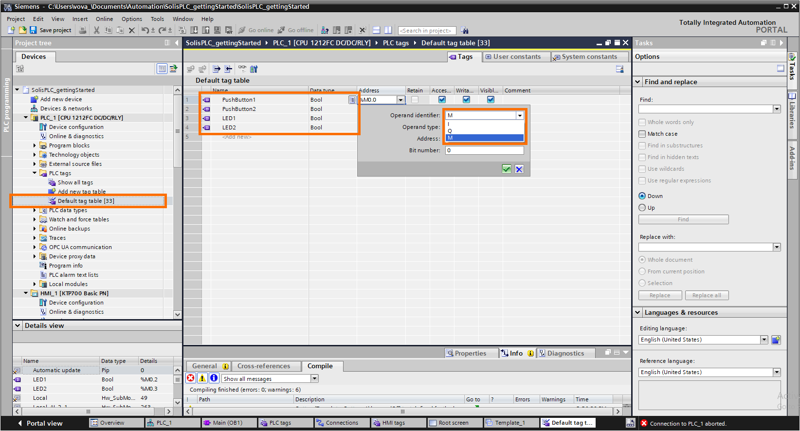
It’s important to note that Siemens-based tags can be of type I, Q and M. “I” specifies the tag as an Input, “Q” as an Output, and “M” as Memory. Although we’re simulating two inputs and outputs, it’s possible to tie them to the physical inputs and outputs of the system, but we won’t be able to write to them via the HMI. Therefore, we’re using memory-based tags, as shown above. In the following tutorial, we’ll demonstrate a different way to store tags on the PLC through an internal database.
Step 2 - Writing Ladder Logic Program Blocks
TIA Portal will pre-populate the project with an initial ladder logic block - Main. It can be found under the PLC “program blocks” folder, as shown below. Once opened, the user can create the logic required by the process. In our case, we’re building two rungs. The first is a motor starter, while the second is a simple XIC -> OTE instruction pair.
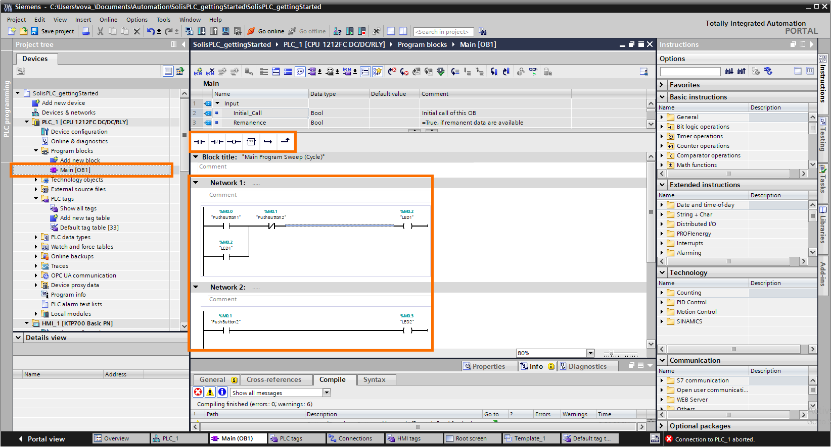
TIA Portal provides a top navigation bar that displays basic instructions and a right-hand-side bar that offers the user all PLC programming instructions imaginable. For a basic tutorial, we’ve kept our instruction set to the XIC, XIO, and OTE, as shown above. By using these three instructions, we can build two “Networks” (Rungs).
Step 3 - Creating HMI Based Tags in TIA Portal
Although TIA Portal is extremely convenient by allowing the programmer to keep all devices under one project, we must specify the tags under each device. This makes sense as one HMI (or PLC) can be tied to multiple systems; the link must be explicitly defined.
In this section, we’re building the tags on the HMI side and are tying them to what we had created on the PLC. It’s important to note that we’re using the PLC-to-HMI connection we created in the previous tutorial; it needs to be in place before linking the two devices.
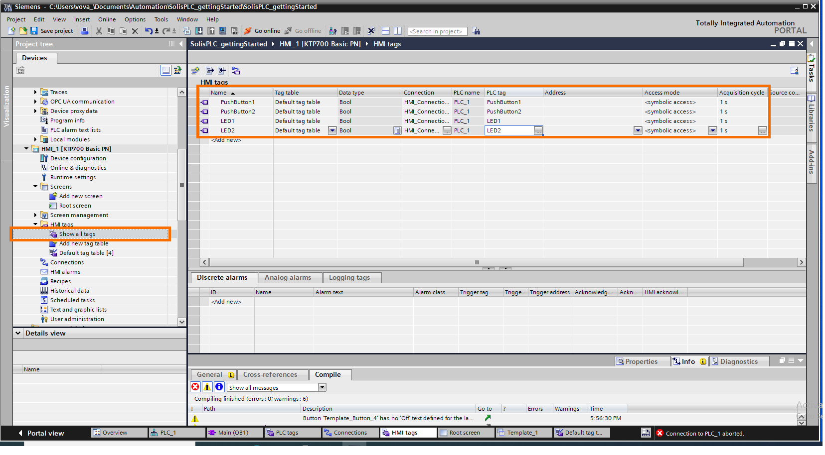
Notice that in the HMI tags, under “Connection”, we’ve specified “HMI_Connection1”. As mentioned above, this connection is what ties the HMI tags to the PLC tags. In addition to the connection, we must specify the PLC tag we’re connecting to. In the example above, the name of the PLC tags matches the ones on the HMI; this doesn’t need to be the case.
As your tag list expands, it becomes more convenient to copy & paste the tags into the HMI.
Step 4 - Creating an HMI Screen and Elements
Under “Screens,” the user can define and design the screens that will be presented on the HMI. Our goal is to create something basic in this tutorial; we’re using the “Root screen”.
Two elements are used in our program: Button and Circle. Let’s start with the Push Buttons.
Step 4.1 - Drag a “Push Button” element onto the screen
Step 4.2 - Select the “Push Button”
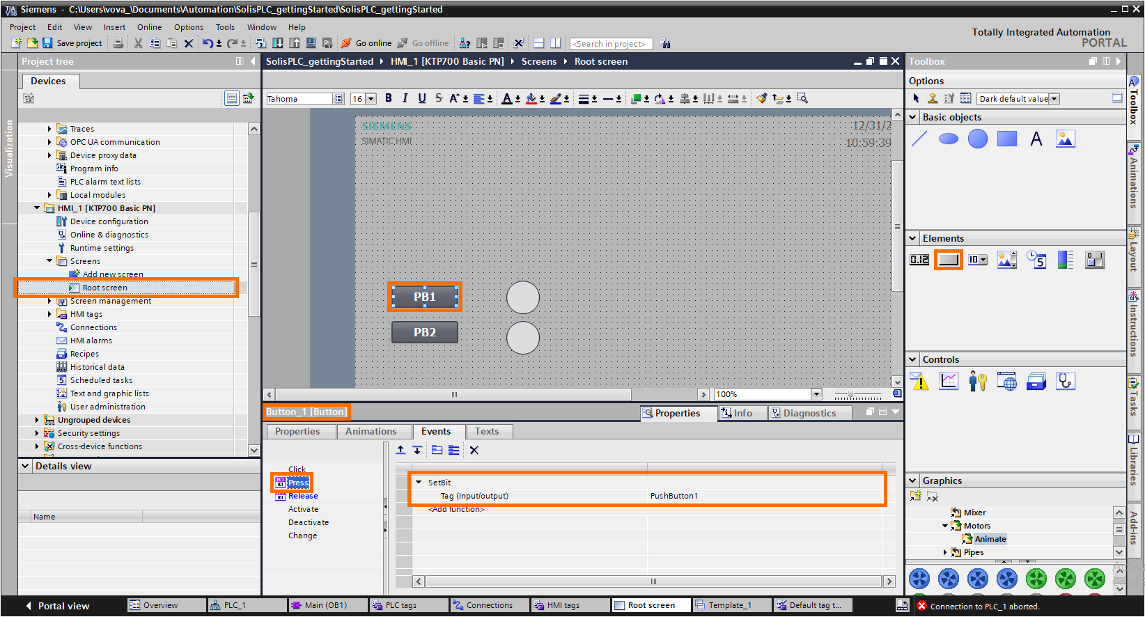
It’s important to note that you must select the right element in TIA Portal, as it’s possible to edit the same settings on other elements. Use the navigation bar and make sure that you’ve selected “Button_1 [Button]”.
Step 4.3 - Add a “Press” event
Under the “Events” tab for the push button element, it’s possible to create various logic based on what happens to the element. In this case, we’re looking to toggle the HMI bit that we’ve created above.
Step 4.4 - Add a “SetBit” event that points to “PushButton1”
The “Press” event must call the “SetBit” function that is used to set the specified bit to “HIGH” or “1”.
Step 4.5 - Add a “Release” event
When the user released the push button, we need to set our bit back to “LOW” or “0”. Although this can be accomplished in logic, we will maintain the HMI standard to set the same bit to “LOW.”
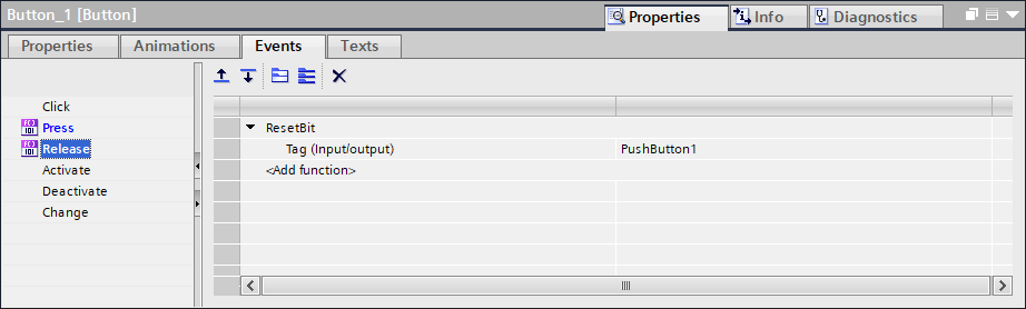
Step 4.5 - Add “ResetBit” event that points to “PushButton1”
The “ResetBit” event will set the bit to “LOW.”
Step 4.6 - Copy and Paste the first button
Step 4.7 - Change the tags of Button 2 to point to the “PushButton2” HMI Tag
It’s important to change both events of the second button to point to the second tag we’ve created on the HMI.
Step 4.8 - Create a Circle element on the screen
We can use a “Circle” element and functions that toggle the color based on one of the tags to display a change in element color.
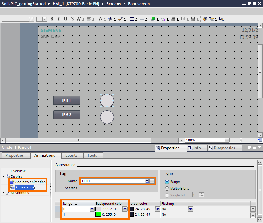
Step 4.8 - Add an “Appearance” animation to the Circle
Under the “Animations” tab, the user can create an animation by clicking the “Add new animation” button on the left-hand side.
The animation will have multiple options. First, we need to make sure that it’s tied to the HMI tag we’ve specified before and that it toggles the color of the Circle to indicate the state. The “Range” tab is used to identify the tag value to check against. In this case, the tag can only take on “0” and “1” and thus we have only those two specified. It’s possible to create an infinite number of animations in the case of analog tags.
Step 4.9 - Copy & Paste a second circle
Step 4.10 - Change the “LED1” tag to “LED2” on the second circle
Step 5 - Simulate the PLC in TIA Portal
The PLC and HMI programs must be simulated separately. Therefore, different software packages are used for each device.
Select the PLC and Press on “Start Simulation”. TIA Portal will notify the user that other connections will be terminated. This is done to make sure that the user is aware of using a local simulation versus an actual PLC.
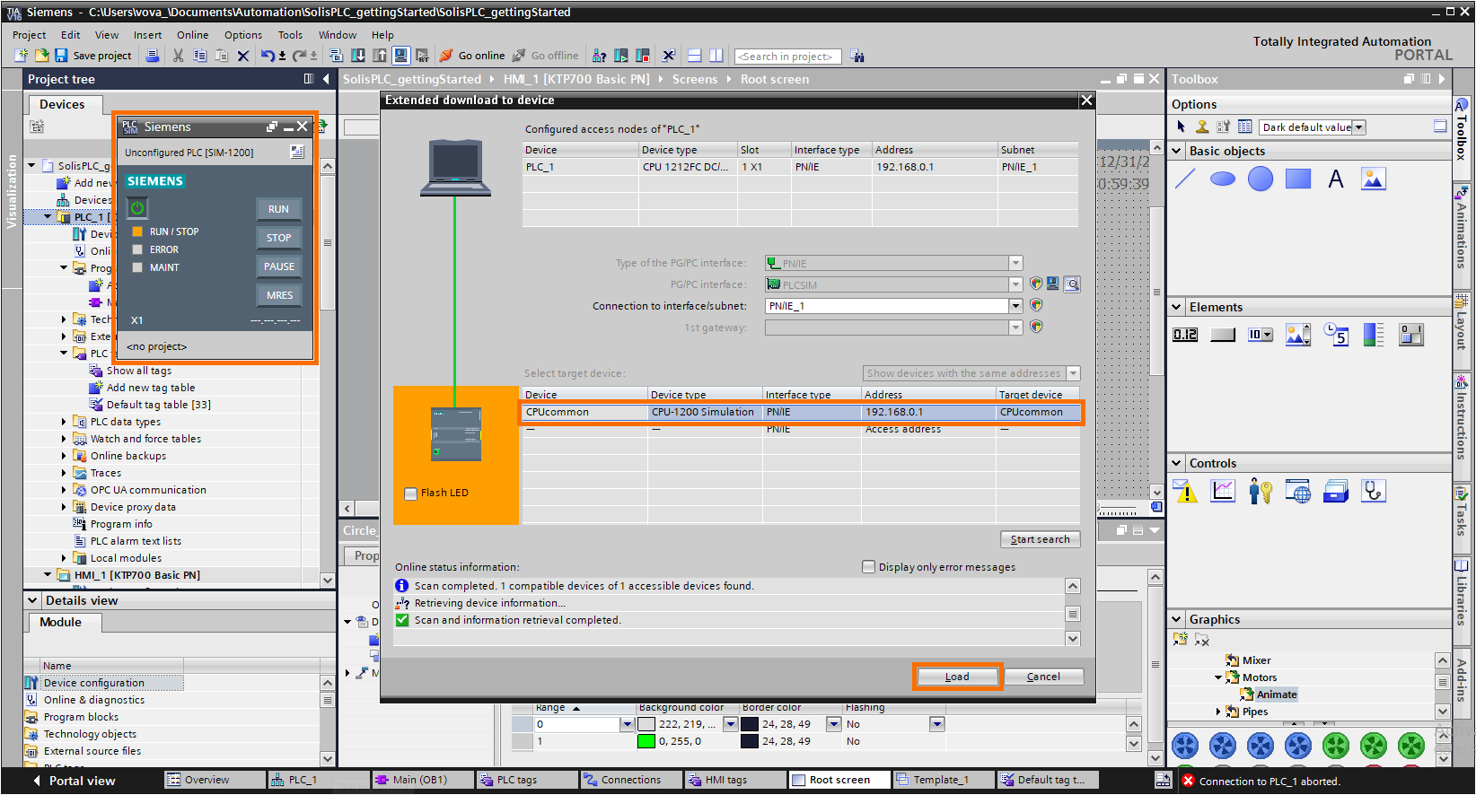
TIA Portal will open the “Download to device” window we saw in the previous tutorial. Although the search function remains the same, the device shown in the “target device” window will be a locally simulated PLC as shown under “Device type”.
Once you connect to the simulated PLC, a new window indicating the state of the PLC along with the usual push buttons will appear. To simulate the logic we’ve built, toggle the PLC into “RUN” mode.
Step 6 - Simulate the HMI in TIA Portal
Select the HMI and press on the same “Simulate” button as above. The HMI simulation uses WinCC software that will launch the main screen as specified by the HMI software.
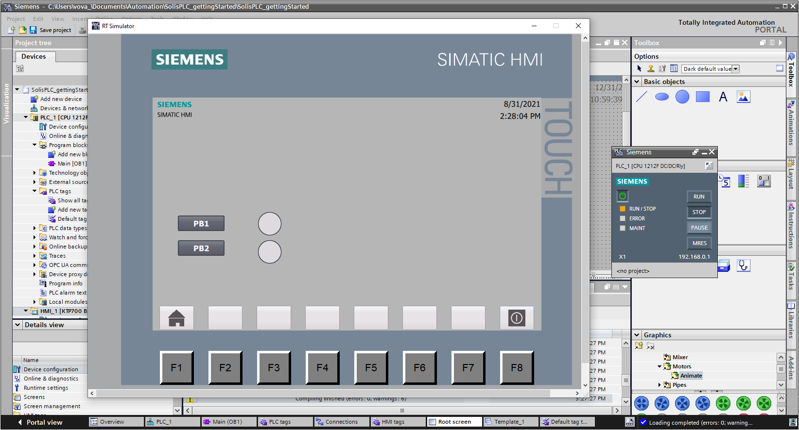
The HMI can be used as you would an actual screen. Press the “PB1” and “PB2” push buttons and observe the change in the color of the Circles we’ve created.
Conclusion on PLC and HMI Simulations in TIA Portal
We’ve created PLC and HMI tags, built a simple ladder logic routine, created an HMI screen, and simulated both devices.
Siemens differs from Allen Bradley in multiple ways:
- First, it’s much easier to integrate various hardware components under the same umbrella in TIA Portal.
- The PLC code layout is different; the user interface appears to be better, but the transition from one manufacturer to the other isn’t apparent.
- The Simulation capabilities are much better in TIA Portal; it’s easy to see the PLC and HMI simultaneously; no additional software packages are required to simulate either one.
