Understanding Advanced Data Types and UDTs in Siemens TIA Portal

Introduction
Data types are a vital concept in PLC programming that help us differentiate between the various parameters we deal with in the industrial world. Advanced data types can be created using combinations of other primary PLC data types as a structure. This helps with reusability and efficiency and accelerates programming.
In this tutorial will look at some advanced data types used in Siemens PLC programming. We will learn how to use them, how to apply them to real world projects, and how to customize them in Siemens TIA Portal.
Prerequisite
To follow along with this tutorial, you will need:
- A basic understanding of basic data structures and types
- TIA Portal – TIA Portal V16 is being used in this tutorial
- PLCSIM Advanced or PLCSIM
Arrays
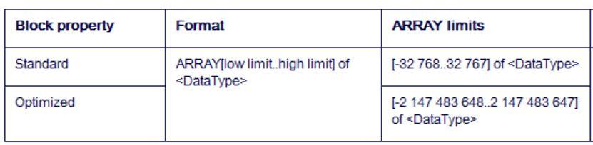
A tag of the ARRAY data type represents a structure consisting of a fixed number of components of the same data type. The index limitations are defined in square brackets, and the data type is defined after the keyword "of" when creating an ARRAY tag. The ARRAY limitations can be established either statically with integers, global and local constants, as formal block parameters, or dynamically with ARRAY [*]. The low limit must be equal to or less than the high limit. An ARRAY can have up to six dimensions, each with its own set of bounds separated by a comma.
Array Addressing
Fixed or variable indexes are used to address ARRAY components. ARRAY tag components can be considered like tags of the same data type.
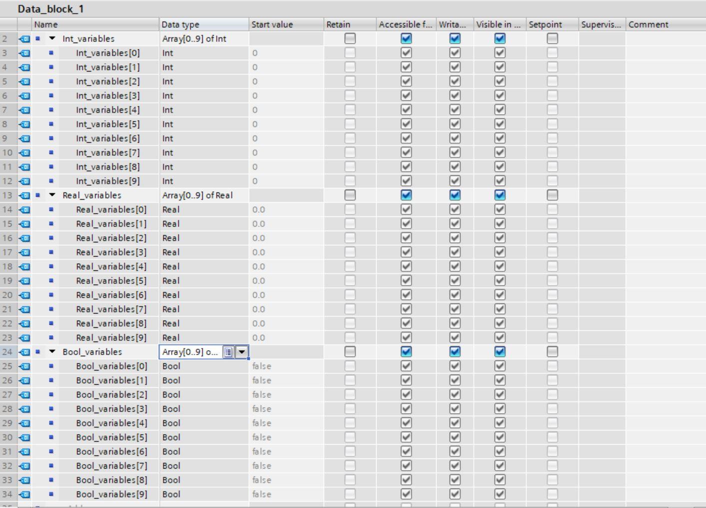
Let us create an array consisting of ten integers, ten reals and ten Boolean.
Open TIA Portal, create a new data block and customize the array as shown in the image below.
The limits for creating arrays are described below.
Struct Data Type
The STRUCT data type represents a data structure with a defined number of components of distinct data kinds. A structure can have components of the STRUCT or ARRAY data types. Data can be grouped according to the process control system and parameters can be transferred as a single data unit using structures.
A STRUCT tag always begins in a non-optimized block at a word limit, at an even-numbered byte. Individual components are then located in the memory in the sequence in which they were declared. STRUCT tags take up memory until the next word limit is reached. A nested structure is a substructure of another structure. It is possible to nest up to 8 buildings deep. The "InOut" section allows for a maximum nesting depth of 9 structures.
Creating Structures
Control Scenario
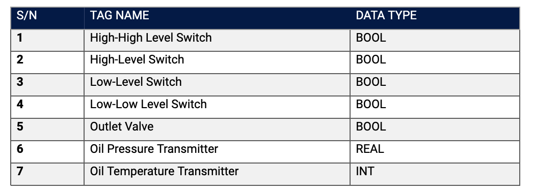
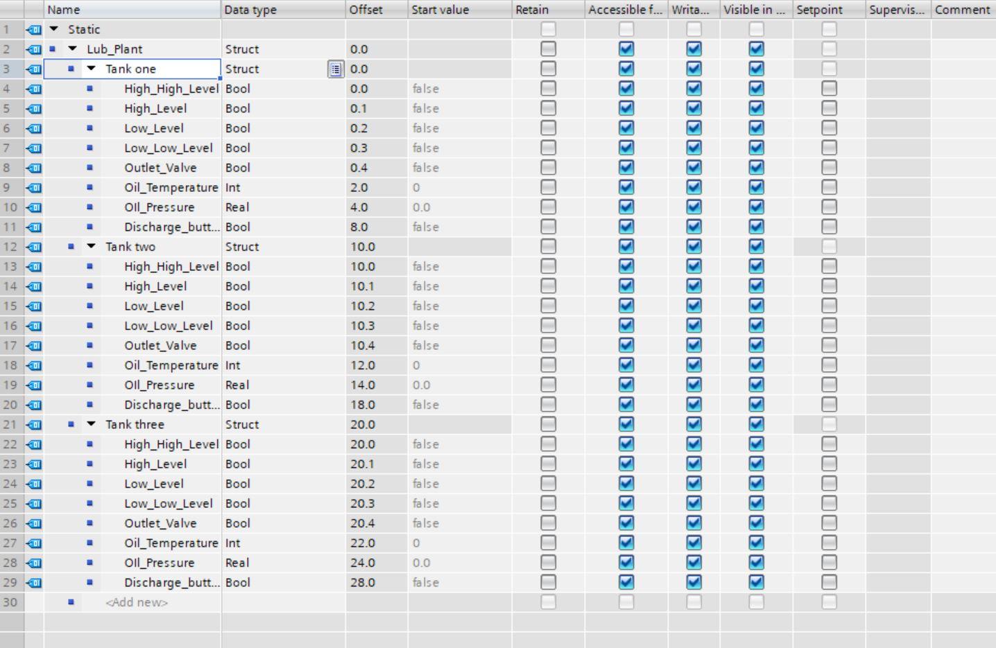
We have a lubricating plant with three tanks for storing lubricating oil after processing. The system consists of inputs and outputs. For each of the tanks, these are the following signals.
Create the STRUCT as shown in the image below
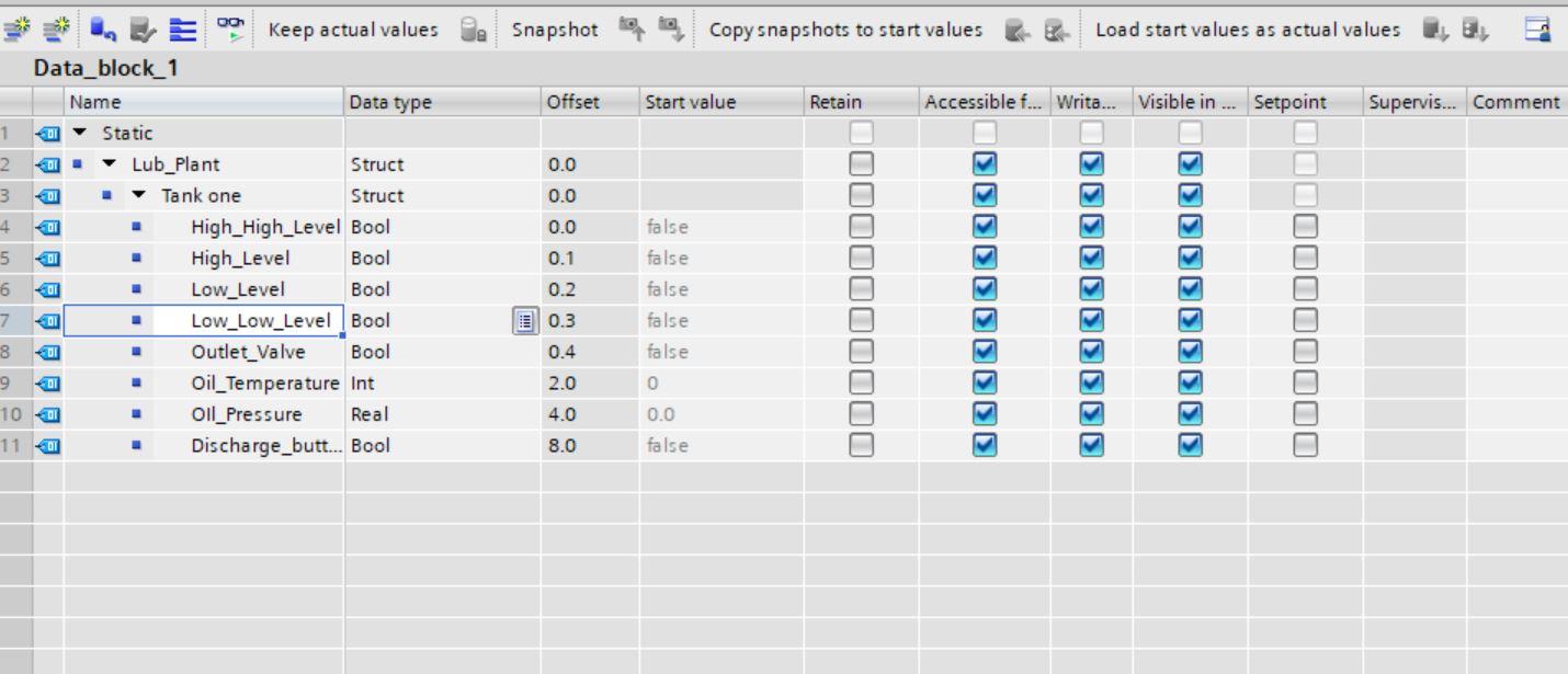
As we can see from the image above different data types are contained in the STRUCT data type.
To create other tank parameters simply copy tank one parameter, paste it and rename.
Using User Defined Types (UDTs)
When generating data blocks, you can designate PLC data types as a type. You can create several data blocks based on this type, all of which have the same data structure. These data blocks can be customized by changing the actual values for the appropriate task. Creating a PLC data type for a lubricating plant depot, for example. This data type can subsequently be assigned to many data blocks, each containing a different quantity of data.
Creating User Defined Types (UDT)
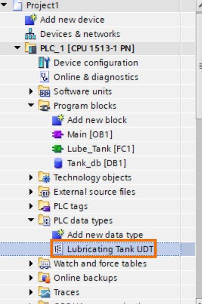
Let us start by creating a new PLC data type. Under project tree, navigate to PLC data type and create a new one.
Create the following tags as shown in the next image
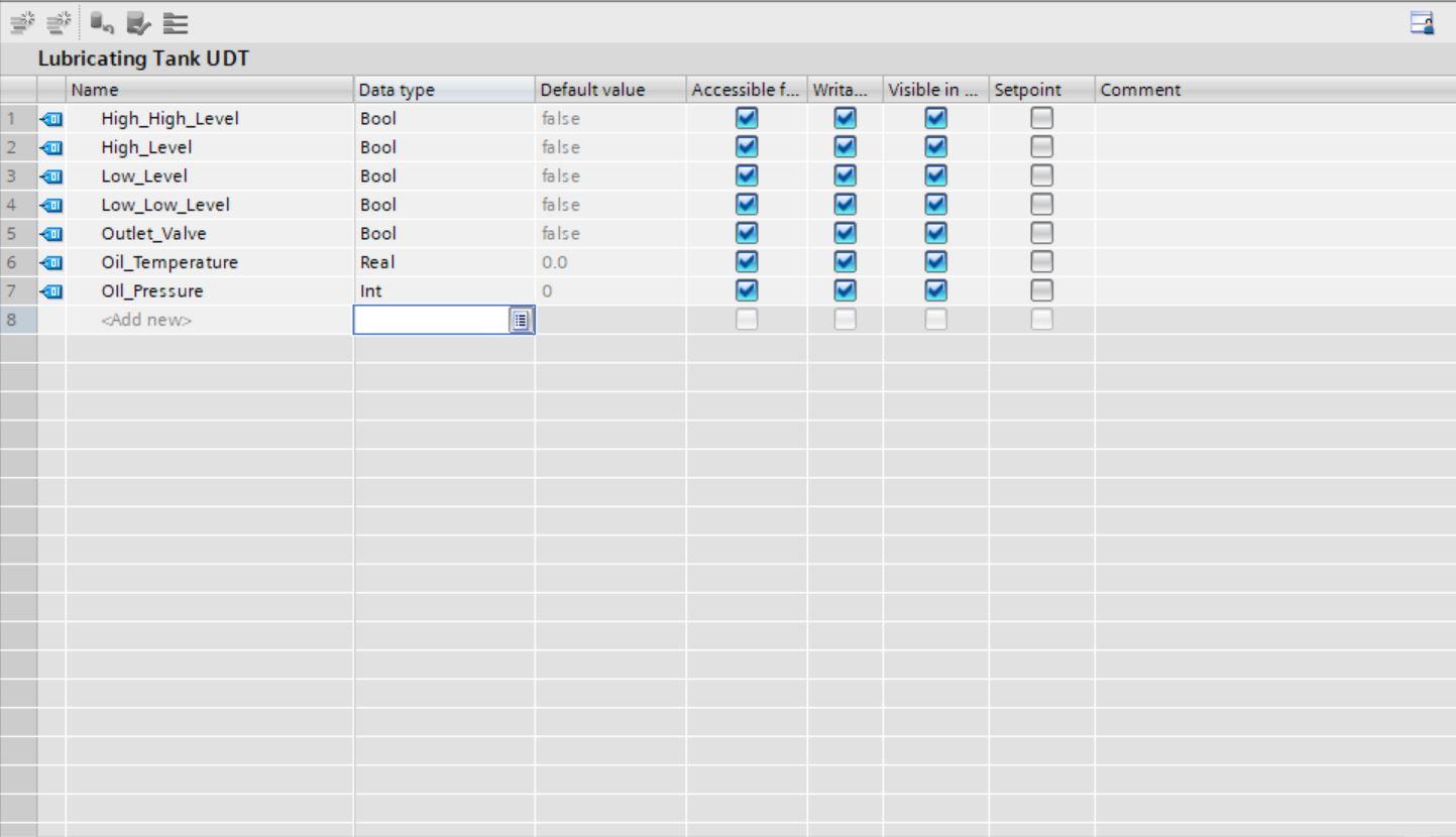
After creating this, the UDT can be exported and imported into another PLC project. A common practice is to save them as libraries for reusability.
We can go on to create a data block for our three tanks and use the UDT. Remove the optimized block access.
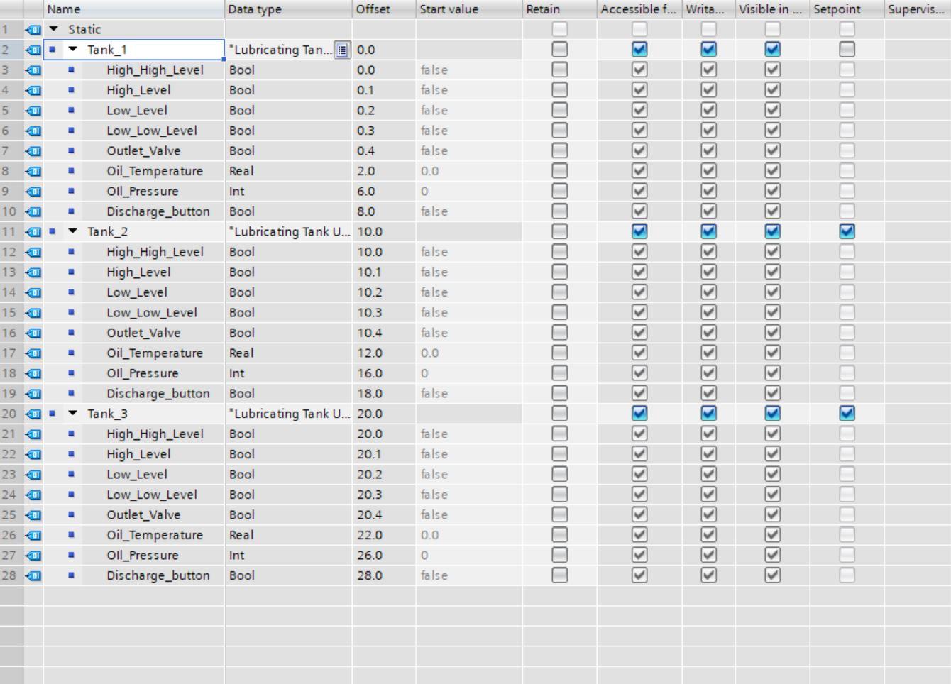
Each of the three tanks can use the same UDT for their IOs (take note of the data type). Instead of creating different tags for all tags, a simple UDT has solved this problem. Let us use the UDT in a simple program.
Testing the UDT
We will create a function that will hold some calculations for our Lubricating plant. Create a new function with the following parameters. Create the parameters as an internal parameter local to the function.
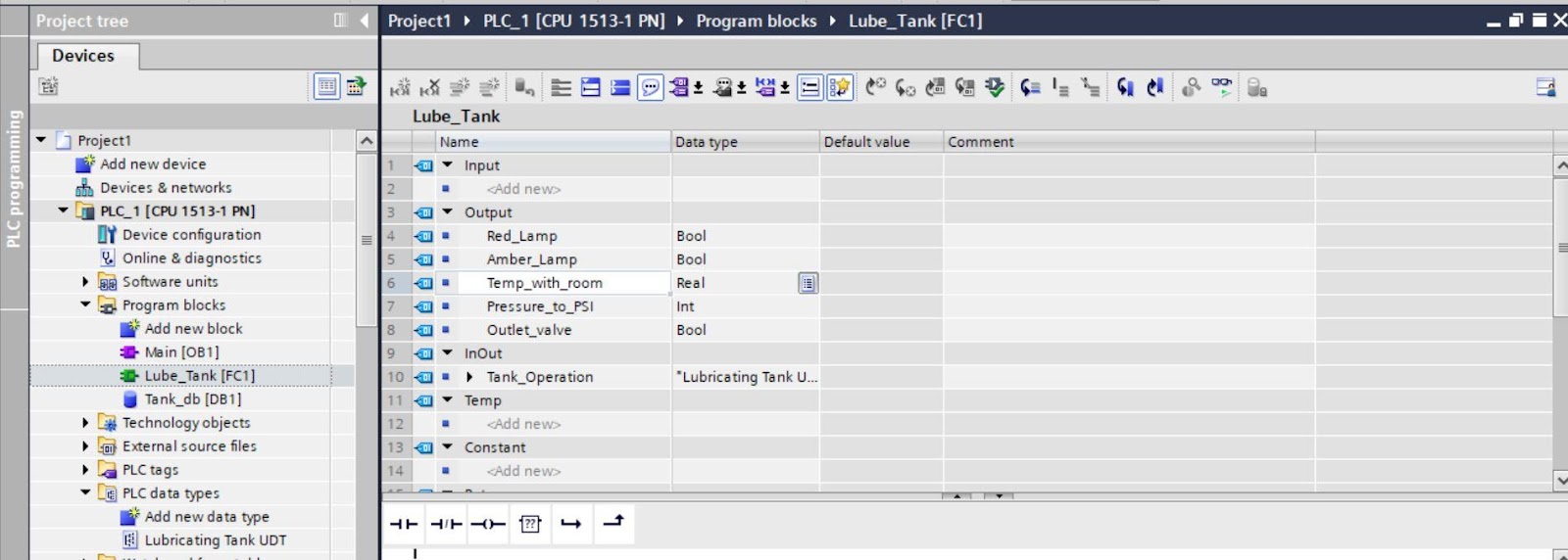
Here, we have created lamps as outputs for warning, an outlet valve for discharge, and temperature inclusive of room temperature and pressure in PSI unit.
Notice that the Tank operation parameter that uses our created UDT is under the INOUT type. This is because our UDT comprises inputs and outputs parameters.
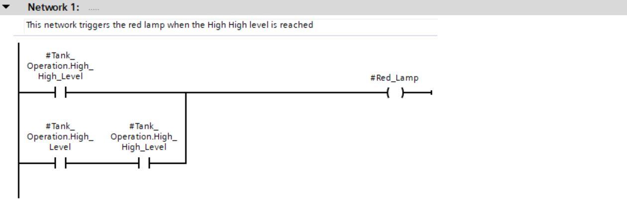
Network one is used to check for High-High condition level of each tank.
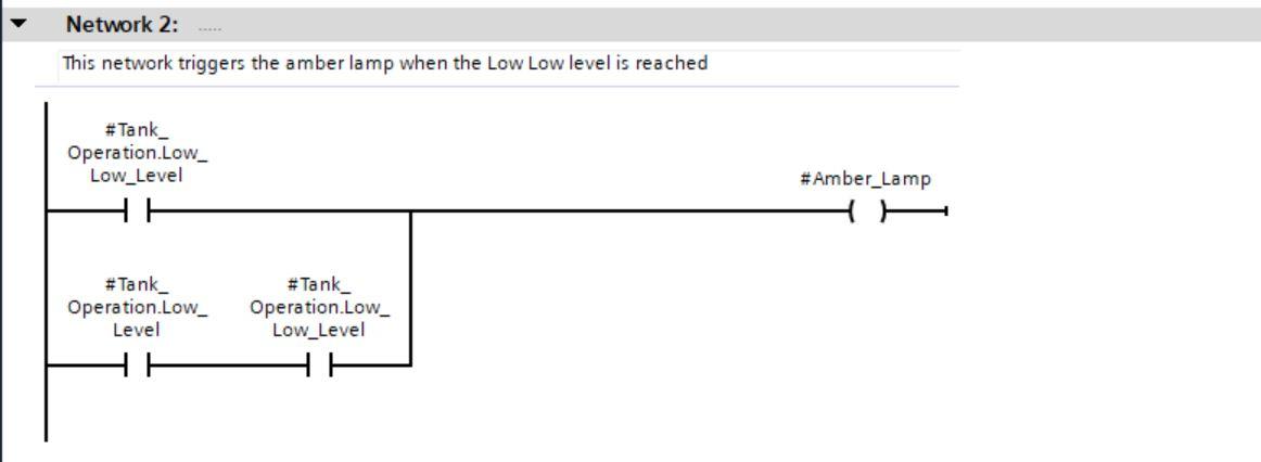
Network two is used to check for Low-Low condition level of each tank.
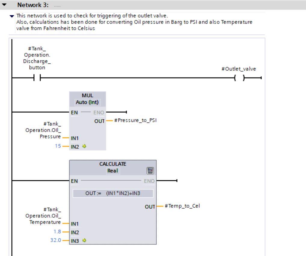
Network three has calculations for Pressure from Barg to PSI and Temperature from Fahrenheit to Celsius.
It also shows the control for activating the outlet valve through the discharge bit.
Dragging the Function from the project tree to the programming area of OB1 shows the following
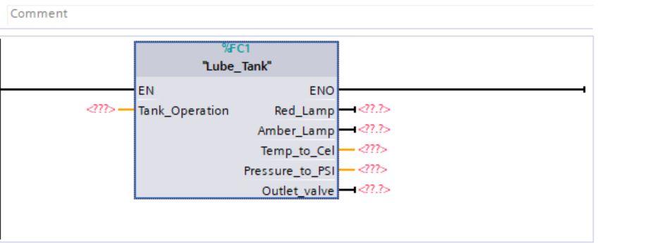
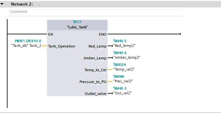
Complete the tagging of the FC as shown in the image below

Tank Operation takes the Tank one DB parameters for tank controls.
Red Lamp M2.0 will be tagged to a physical lamp same as Amber lamp M2.1
Temp_to_cel takes the temperature converted output
Pressure_to_PSI takes the converted pressure
Outlet value is the physical valve for discharging the liquid.
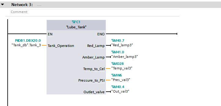
Replicate the same for tank two and three by changing the parameters to their respective tank DB number.
Compile and download the program into PLCSIM.
Testing of Program
Now for testing, edit some parameters of the individual tanks in the DB.
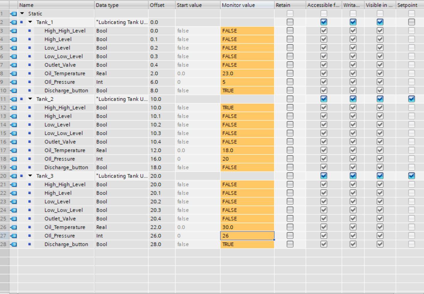
We can see the different states of the tanks. Let us look at the networks.
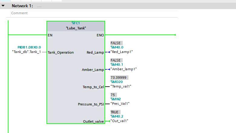
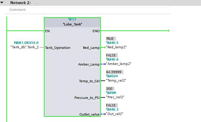
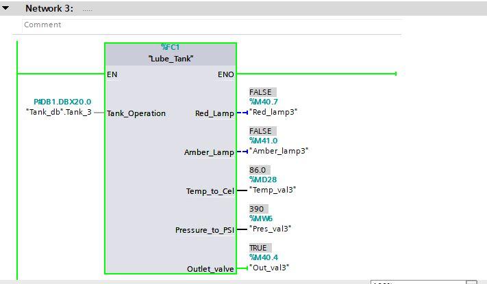
We can see that Tank one and tank three outlet valve is opened while two is closed. We can also the converted Temperature and Pressure valves for all tanks. We can see that the Tank two red lamp is on due to the activation of the High-High sensor.
This can also be done by creating the tags for the different tanks but that would be more cumbersome; UDT has simplified it. Additionally, if more tanks will be added in the future, it would just be a matter of creating a DB tank parameter with the UDT.
Download the program into the simulator.
In the extend to download screen, select Siemens PLCSIM Virtual Adapter as the PG/PC interface then search. After the PLC device is located load the program.
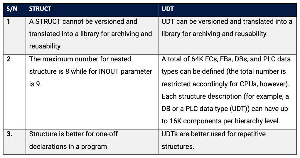
Difference Between STRUCT and UDT
At face value, a STRUCT and a UDT have many similarities but there are some differences between them as highlighted below.
Conclusion
Time-saving is one of the advantages of UDT as it helps in code reusability; It helps makes the project lifecycle more efficient. Once a UDT has been created, it can be multiplied in the program and transferred as a library to another project. A good practice for UDT is that only the needed tags should be defined to avoid wastage of PLC memory.
