Building an Alarm and Diagnostic System In Siemens Tia Portal

Introduction
In a previous tutorial, we’ve covered a useful tool for PLC programming, States Machines in Ladder Logic. This time, we’re going to extend the use of States Machines and build a structured path toward fault diagnostics and machine alarms development to create a solid alarm function block in Siemens’ TIA Portal.
A PLC program is able to operate and maintain production over machines and whole plants, but the interaction with the physical components leads to undesirable and often unsafe system behaviors. When developing those kinds of systems, it’s crucial to determine and code diagnostic and alarm algorithms capable of preventing, warning, and blocking unstable operations. This can be achieved by building a PLC logic to map the most inconvenient conditions and take some action over them. Most of the time, those actions are in the form of HMI/SCADA alarms, letting the system’s operator know an issue has been detected.
Moreover, when considering States Machines, every state transition’s conditions and actions are easily linked to warnings and faults—adding an extra value to alarms, in the sense of bringing continuity and clarity to the operation.
Digital Alarms in Tia Portal
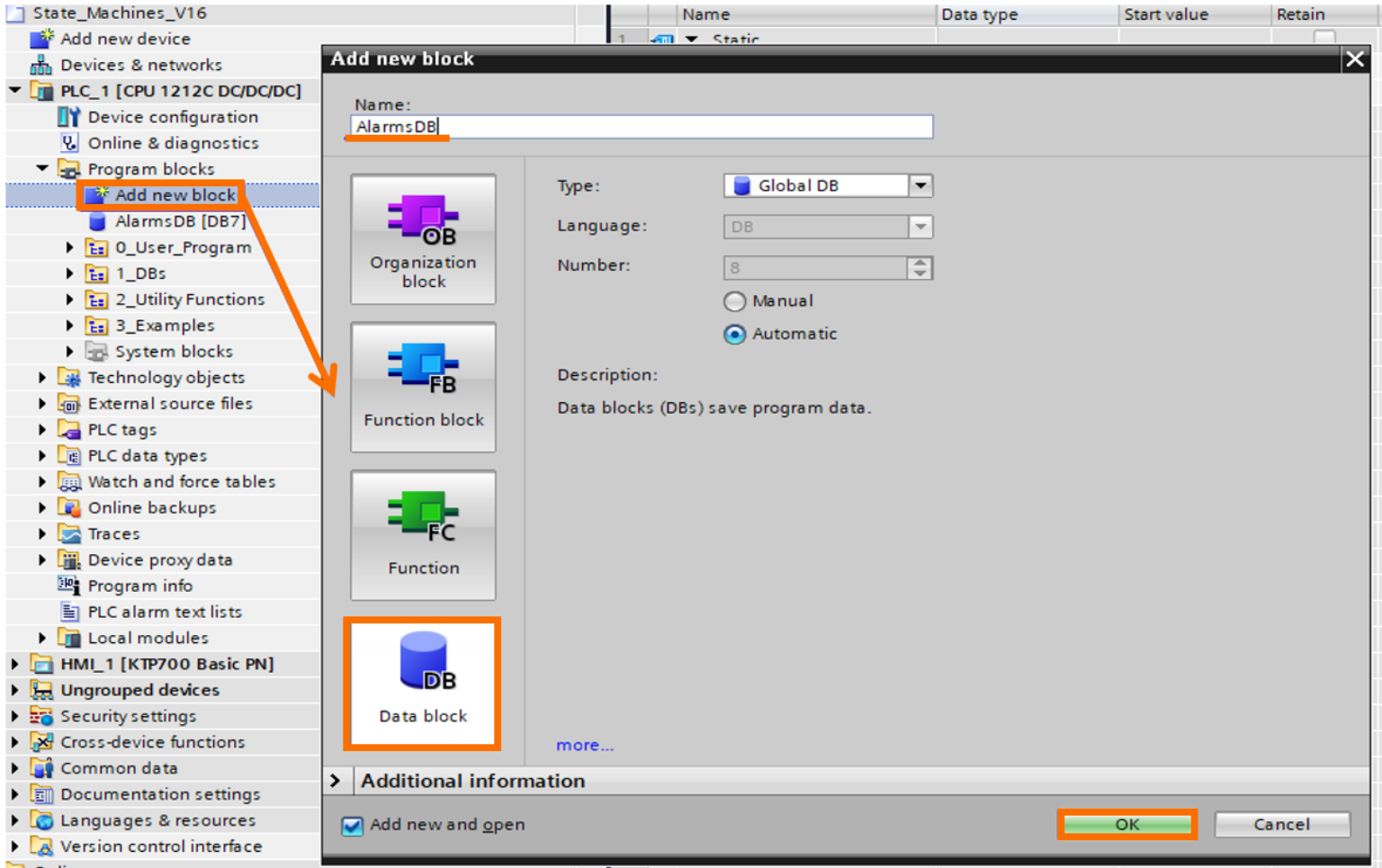
Digital alarms in Tia Portal are represented by a boolean signal contained in a word-type variable, so let’s build a simple alarm example. First, we need a Data Block to declare and store the alarm's values.
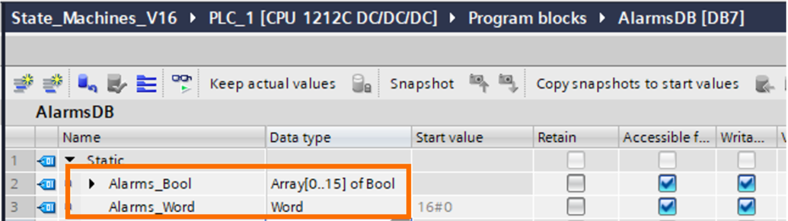
Initially, we need a set of Bool variables (array of 16 bools) and a word-type variable. The PLC logic will be responsible for writing the alarm’s status in each individual Alarm_Bool and then gathering all bools into the Alarms_Word, which will be accessed from the HMI.
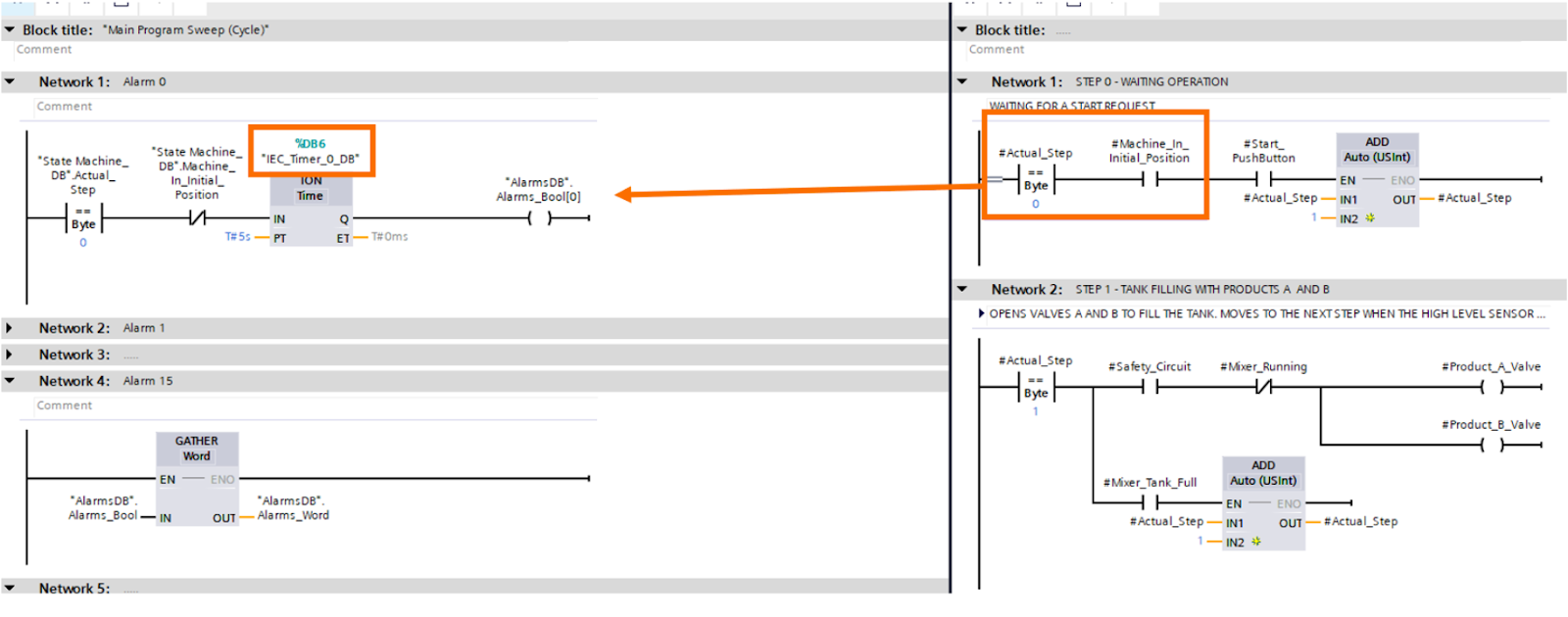
The state machine program can evaluate the conditions for activating the alarm bools. In our example, our first alarm bool is actuated when the machine state is in the initial state (“State Machine_DB”.Actual_Step==0) AND the machine’s Initial_Position bit isn’t activated. It’s often useful to set a monitoring time for each alarm condition, in this case, a TON(Timer On Delay) instruction is used to detect these conditions that have been active for five seconds.
That network’s structure can be replicated for all other 15 alarm conditions as you please, and after that, we need to convert the signals from the bool variables to the word variable. There are a number of ways for converting a group of bools into a word; for this tutorial, we’re using the “Gather” block.
Now that we’re all set from the PLC side, we need to add the HMI to our project.
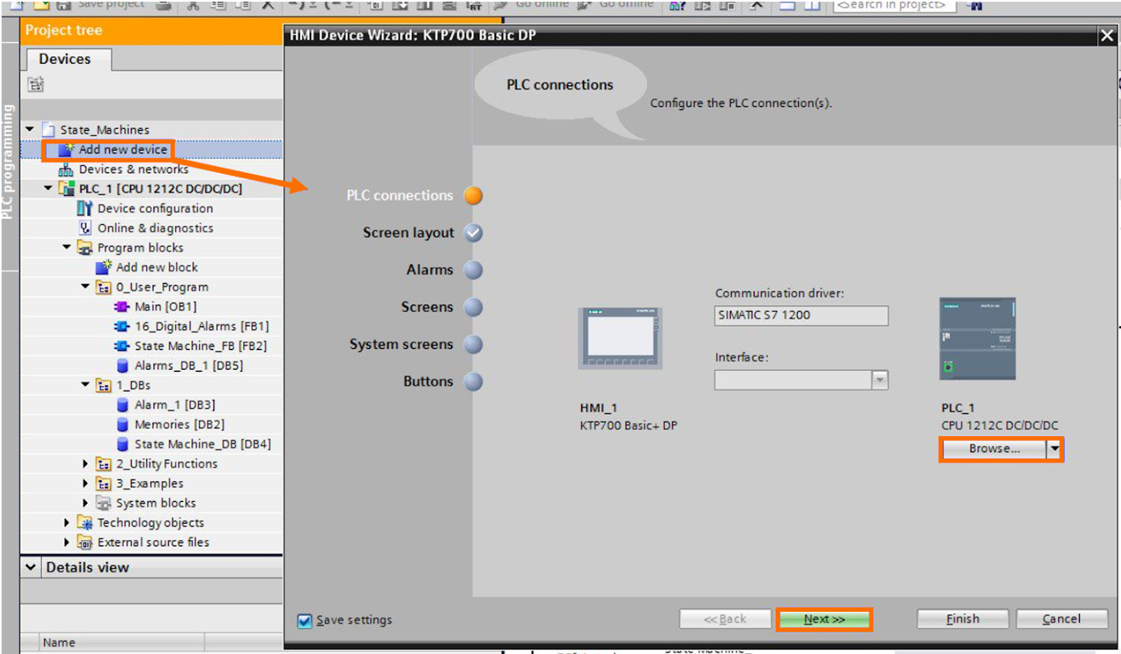
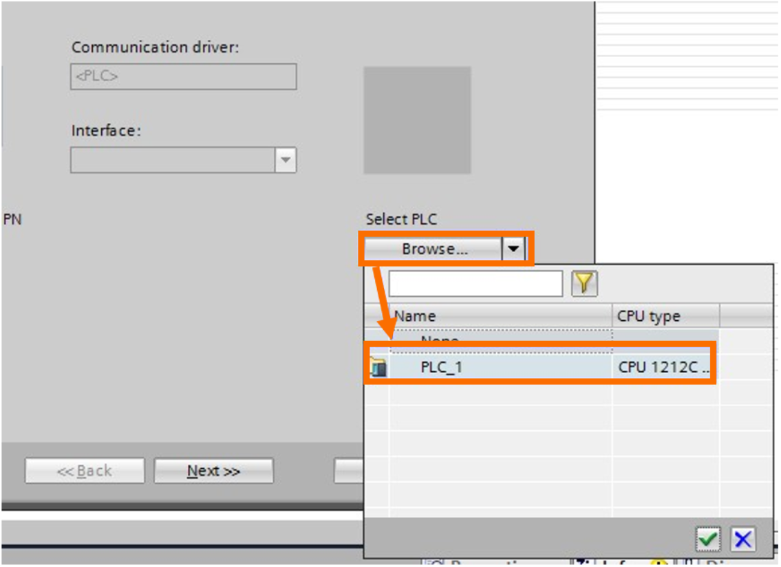
Select the HMI Device that’s convenient for your application and click the “Browse…” button to easily create the PLC-HMI connection.
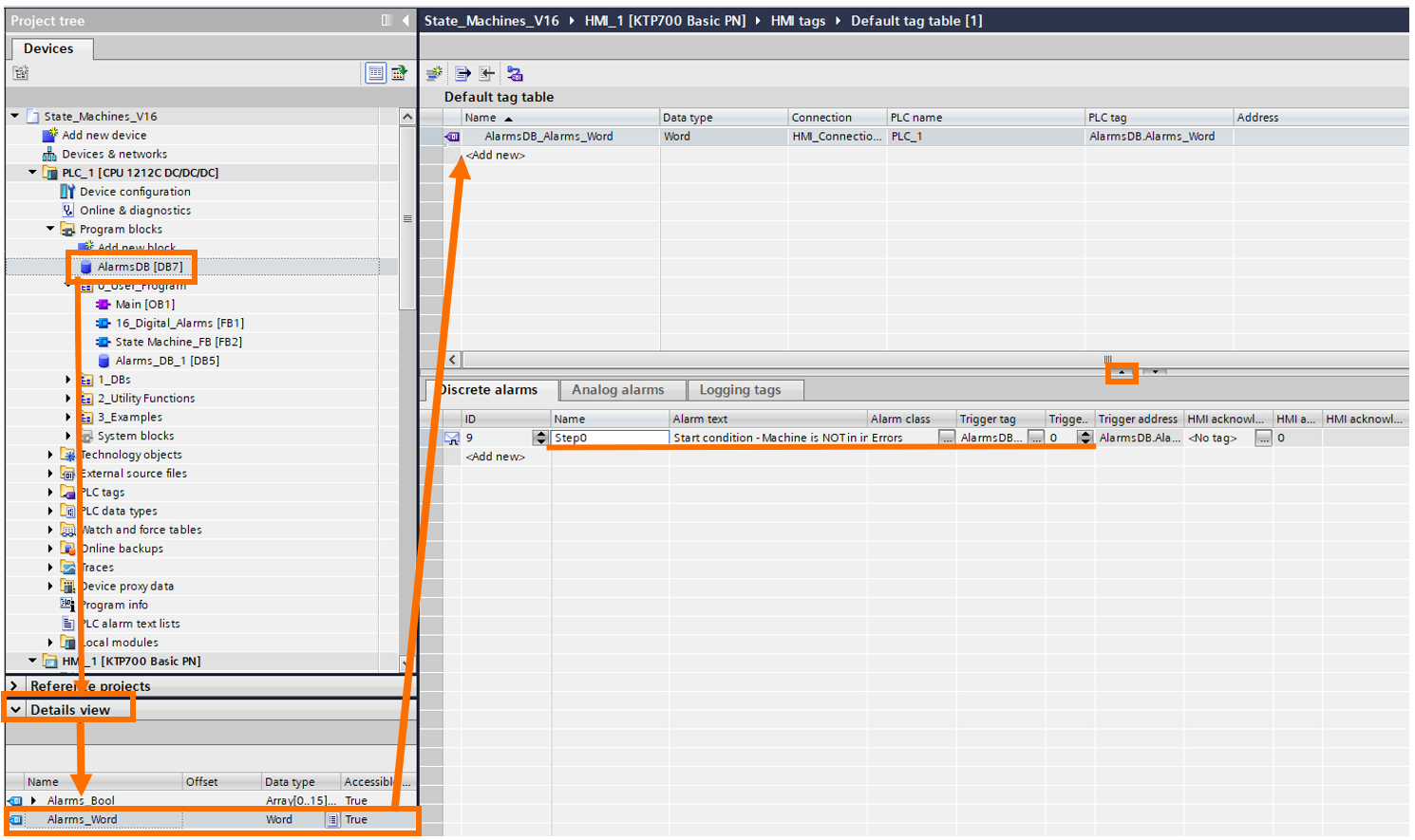
All tags needed from the PLC should be replicated in the HMI Tags.
In the “Details view,” a summary of the PLC tags can be easily accessed by selecting the desired Data Block (AlarmsDB) in the project tree, and it’s then possible to drag and drop the tags from the DB to the HMI tag table. Once our Alarm_Word is replicated, discrete alarms can be associated with each bit of the word. In our example, the first bit of the word (column Trigger bit = 0) will trigger the alarm message: “Start condition - Machine is NOT in initial condition”.
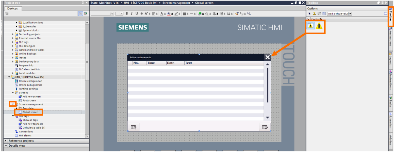
The alarm messages are shown in Global Screen (a window will pop up over the HMI screen) when an alarm is active. The alarm window, message, colors, activation, and properties can be personalized on the global screen over the Screen Management item in the project tree.
Structured 16 Digital Alarms Block
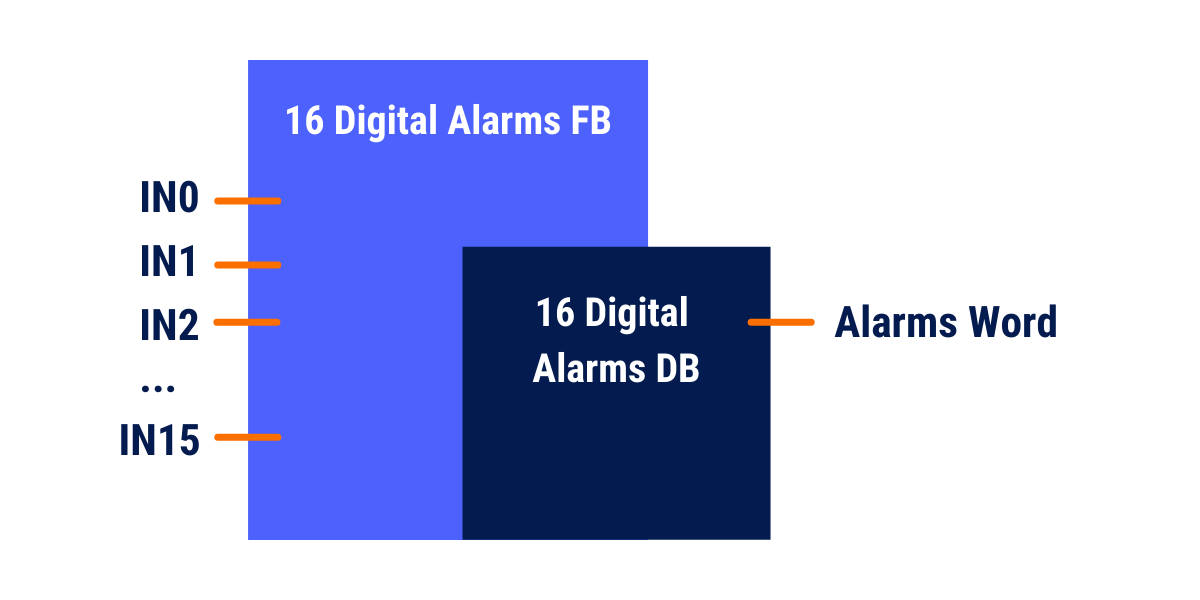
When programming PLC systems, it’s important to standardize and build well-structured pieces of code, since it makes it easier for expansions and later development and debugging, and online monitoring. Even though the way we’ve just implemented our first Alarm in Tia Portal is functional, it does bring some development tediousness in creating multiple conditions, TONs, and generating a great number of networks for debugging. With that in mind, let’s develop a simple Function Block capable of returning the Alarm word. At the same time, all the developer has to do is execute the FB and nominate an alarm condition for each block input.
Ladder Logic
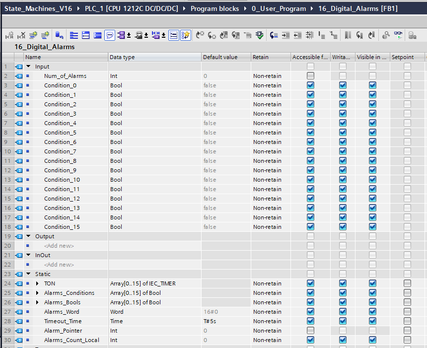
Our Function Block needs an integer input to determine the number of digital alarms (from 1 to 16 alarms) and an extra boolean input for each alarm condition. The static variables are necessary for executing the code itself and storing each alarm state.
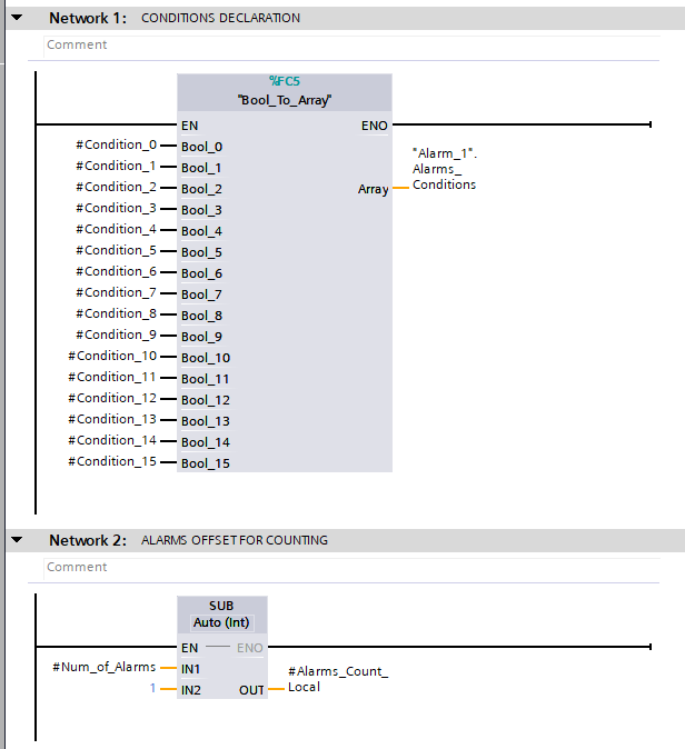
For the logic itself, first, we need to convert each bool state to an array of bool, since it will make it easier to iterate between each condition over the code. In Network 2, we’ll also offset the Num_Of_Alarms input by one, just because the count of alarm variables starts from 0, instead of 1.
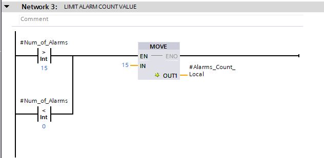
It’s also useful to limit the number of alarms from negative values to 15, the maximum of 16 alarms.
Now, we’re going to test the alarm condition itself. We’ll use a for loop in ladder logic to iterate over all stipulated alarm conditions, timers, and bool outputs. The alarm_pointer variable is declared as an integer static, incrementing by one after each iteration. For each of the array-type variables, it’s possible to address its index to the alarm_pointer value, in the following format: “#Array[#Alarm_Pointer]”. For each instant PLC’s CPU execution cycle, the array’s index is equal to the value of Alarm_Pointer.
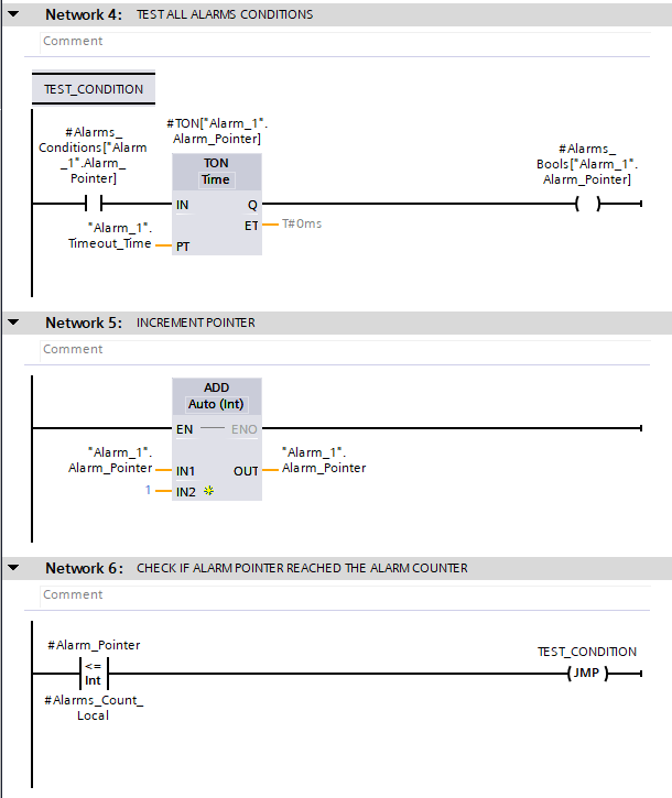
*If desired, it's possible to create different groups of alarms (for each Alarm FB individual Call) to accommodate multiple timeout values. E.g.: Alarm_Group_1_DB.Timeout_Time= 5s
Alarm_Group_2_DB.Timeout_Time=1M
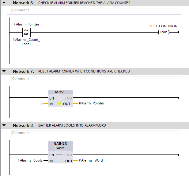
To exit the for loop (NOT JUMP to TEST_CONDITION), the value in Alarm_Pointer should be higher than our stipulated Alarms_Count. Once the loop ends, we need to reset the Alarm_Pointer value to zero and gather the Alarms_Bools into the Alarms_word to output the desired states.
Creating Alarms for the Mixer Machine
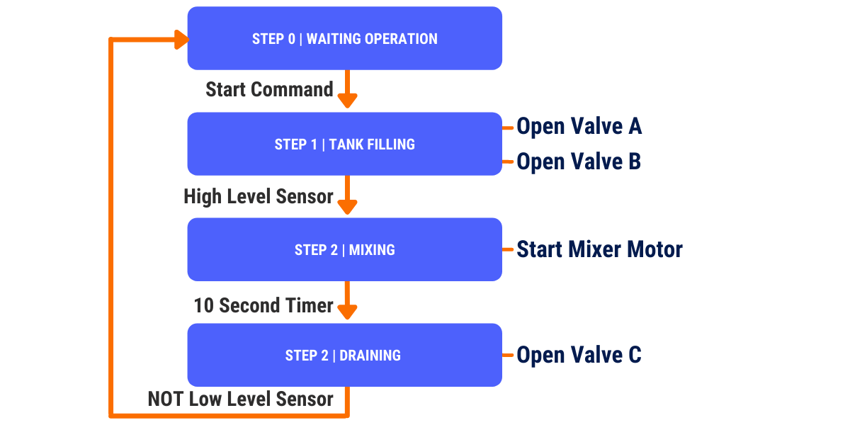
Since our FB is ready, let’s jump to a practical example of building alarms for our mixer machine from the last example, its state machine covers the following states and transitions.
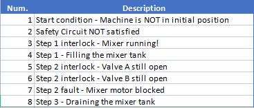
Initially, we need to project and list the alarms we need for the state machine and its description.
Let’s add a call of the 16_Digital_Alarms FB to our main routine by dragging the FB from the project tree and dropping it into the target network.
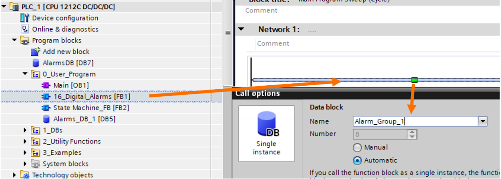
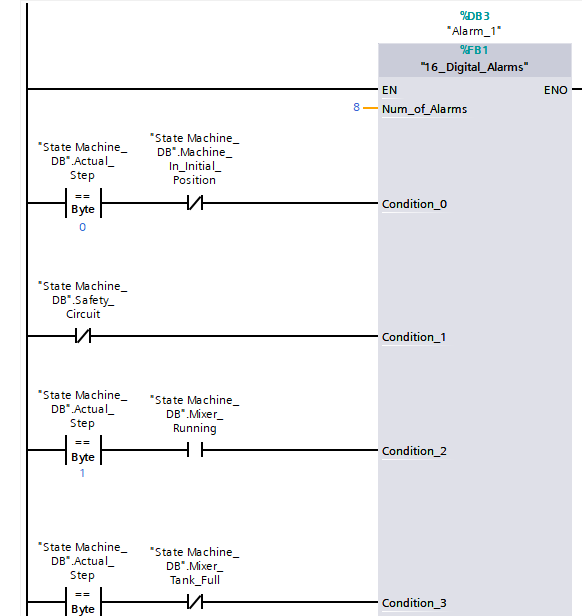
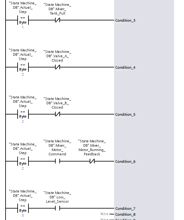
The Function Block needs to be fed with the number of alarms input (the integer value 8, since we’re creating 8 alarms) and every condition that leads to each alarm.
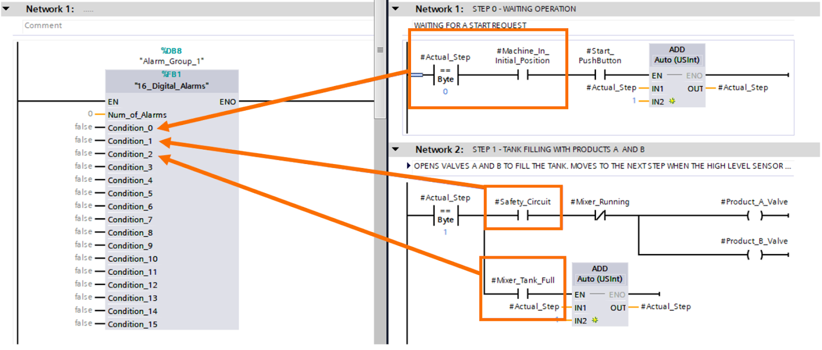
Tip: you can press F12 key to divide the screen horizontally making it easier to visualize two windows of code and drag and drop tags/instructions from one screen to another.
The next step is to link the Alarm Word tag from the PLC to the HMI tags and allocate every message to its trigger bit. Some alarms can be configured to the Warning class, instead of Error.
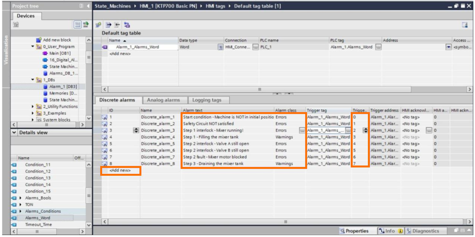
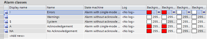
On the HMI alarms page, it’s possible to configure and customize alarm classes.
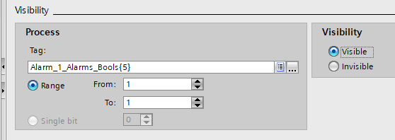
Besides popping up alarm messages on the screen, it’s also very useful to utilize the alarm signals to customize elements in HMI. For instance, let’s create a Valve Fault animation linked to our sixth alarm (Valve B Fault).
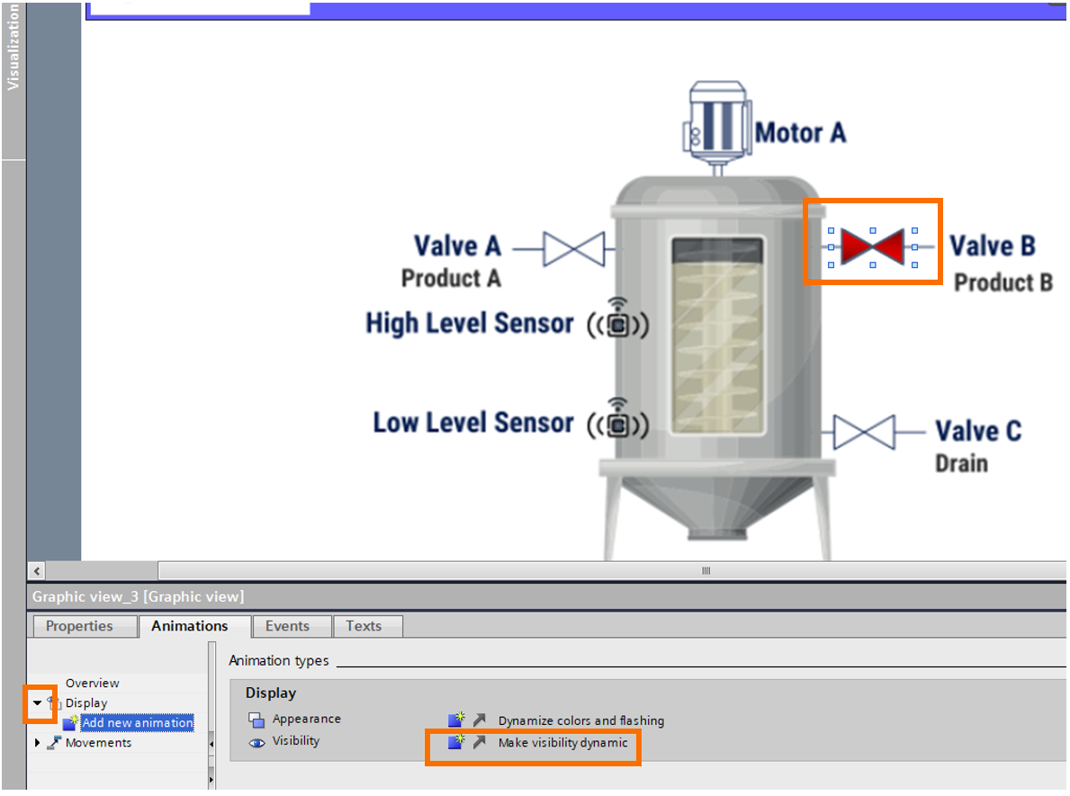
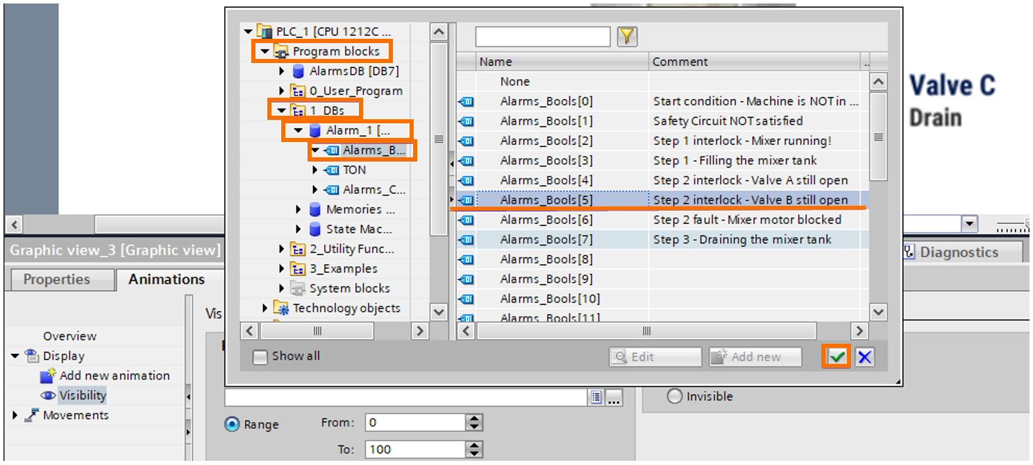
It’s easy to link the visibility of a red valve image over the regular valve to the corresponding alarm bool value. We then choose the image, which represents a fault in the equipment, to be visible when the alarm tag is equal to one.
Conclusion
The development of Alarms & Diagnostic systems is crucial to help operate and maintain PLC-based machines and plants. A well-structured alarm system not only achieves completeness on the main objectives (Clarity, continuity of process, and maintenance collaboration) but provides a clear and intuitive way of reproducing the PLC logic over all kinds of programs, giving the developer all tools needed to program and monitoring alarms, as well as treat the diagnostics data on future user functions such as data analysis.
