Programming a State Machine in Ladder Logic

Introduction
A state machine is an abstraction of a machine that can be in one of a finite number of states at any given time, wherein in each state there are actions and transitions. Actions are means for the machine to interact with the system, while transitions are certain conditions to be achieved in order to move from one step to another.

A State machine is a powerful tool when it comes to programming procedural industrial systems. It's possible to cover entire machines programs with this methodology, and even split a complex process into several smaller and simpler state machines. Diagnostics and troubleshooting are also facilitated, considering that the lack of transition and action signals are easily noted based on the current step status.
In this tutorial, you'll learn how to build a state machine in Ladder Logic. We'll be using Siemens Tia Portal and an S7-1200 PLC, but the methodology can be applied to any PLC and software that supports ladder logic.
Understanding the general template of a state machine in Ladder Logic

This template covers every instruction and the general structure of a step in ladder logic for the state machine. At first, the network checks whether the current step number is equal to the specific step. Some programmers utilize boolean memories for each step, but personally, I like to work with an integer memory, since it is easier to interact with multiple steps in a single memory.
If the current step is active, then the program proceeds to check interlocks and conditions needed for this step's actions. In a parallel branch, we check all the conditions to move to other steps from here.Since we're utilizing an integer memory to keep the actual step, it makes it easy to standardize a step-by-step logic by incrementing its value by one each transition. Furthermore, moving any integer value to the actual step memory is also useful to move the state machine to that specific step.
Next, let's put the concept into practice and build a simple product mixer machine.
Understanding the Mixer Machine

The mixer machine is composed of two product valves (Valves A and B), a mixer (Motor A), and a drain valve (Valve C). The operation should be initiated by pressing a Start Push-Button, which will open both product valves until the high-level sensor indicates the tank is full. After filling the tank, the mixer will be on for 10 seconds, and after that, the drain valve should be open until the low-level sensor goes off.
Building a State Machine Diagram
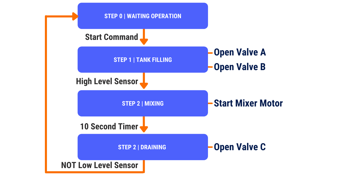
Building the state machine diagram is fundamental to formulating the steps and transitions, as well as anticipating any incoherence that may appear. The mixer state machine should cover the initial state, tank filling, mixing, and draining of the mix. Every transition condition should be the conditions needed for the machine to progress, while the actions of each individual step cover the outputs and logic commands to interact with the system.
Programming a State Machine in Ladder Logic

Now it's time to program each step, its actions, and transitions in ladder utilizing the general template of a state machine. For the initial step (Step 0), we have no actions (the machine is in an idle state) and only one condition, which is the start command.

The start command leads the machine to the filling step (Step 1), responsible to command both product valves (actions) to open until the high-level signal is received from the sensor, covering a transition to the next step (Step 2).

Since the memory actual step value is no longer equal to one, the valves are not open anymore(commands to open are off) and in the new step, the mixer motor output should be on for the estimated duration. A timer of ten seconds is then the transition condition to move the machine state from step 2 to step 3.

The last step consists of opening the drain valve (action) until its transition condition (low-level sensor signal goes off) is achieved. This transition leads to the completion of the process and takes the machine back to an idle state until the start button is pressed, or in other words, we move the machine to the initial step (Step 0).
Conclusion
In this tutorial, we covered a strategy for building state machines in ladder logic, using a simple product mixer as an example. This approach can be expanded to program complex machines with any number of steps. This ladder logic structure is also convenient for alarms development and interaction between machines and other functions from the same code, which is a topic we'll cover in the next tutorial.
