An Introduction to the GRAPH Language in TIA Portal (Sequential Function Chart)

Introduction
In industrial automation, the five IEC 61131-3 languages are pivotal tools for control system programming. Among these, Sequential Function Chart (SFC) language, often called GRAPH in the Siemens environment, plays a significant role. SFC provides a graphical representation of sequential control logic, breaking it down into Steps (actions) and Transitions (conditions). These visual elements offer a powerful way to design and implement sequential control logic for industrial automation tasks.
GRAPH, the name used for SFC in Siemens' TIA Portal, is a versatile programming language that simplifies the creation of complex control sequences. It involves arranging Steps and Transitions in interconnected charts, facilitating a structured approach to control logic design. Steps represent specific actions or operations, while Transitions define the conditions that trigger the progression from one step to another.
In this tutorial, you will learn how to harness the capabilities of the GRAPH language in TIA Portal. You'll discover how to create and connect Steps and Transitions, build conditional branches, use simultaneous branches, and employ endpoints for advanced control logic design. Additionally, we'll delve into the programming of actions within Steps and conditions for Transitions, demonstrating how to bring your automation sequences to life within the TIA Portal environment.
Prerequisites
To follow this tutorial, you will need an installation of TIA Portal. We will be using the latest versions to date (v18), but you can use any other version. No additional hardware or software is required.
New project configuring and creating a new block in GRAPH language
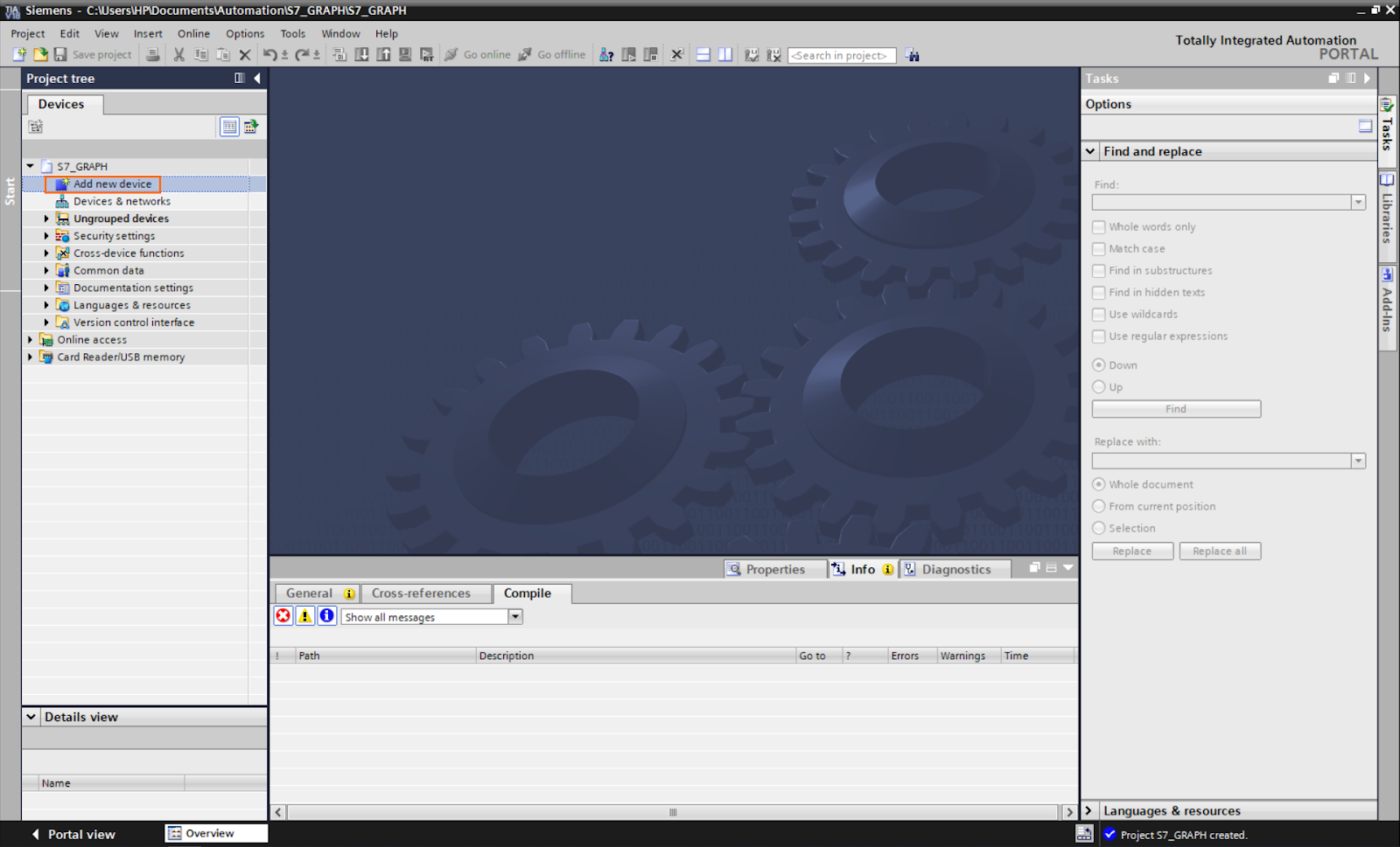
Let’s start by creating a new TIA Portal project. Once done, click on “Add new device” in the project tree.
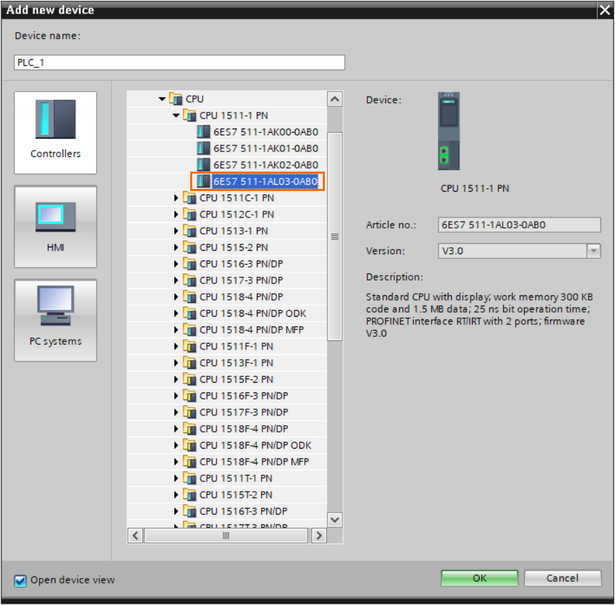
After that, we have to choose a CPU. You can select the CPU of your choice. Here, we will use a 1511-1 PN CPU.
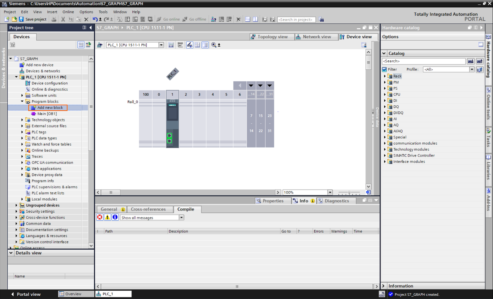
Now that the station is created, we can add a new function block using the GRAPH language. Click on “Add new block” in the program blocks section of the project tree.
Click on the “Function block” section, then select “GRAPH” in the languages list.
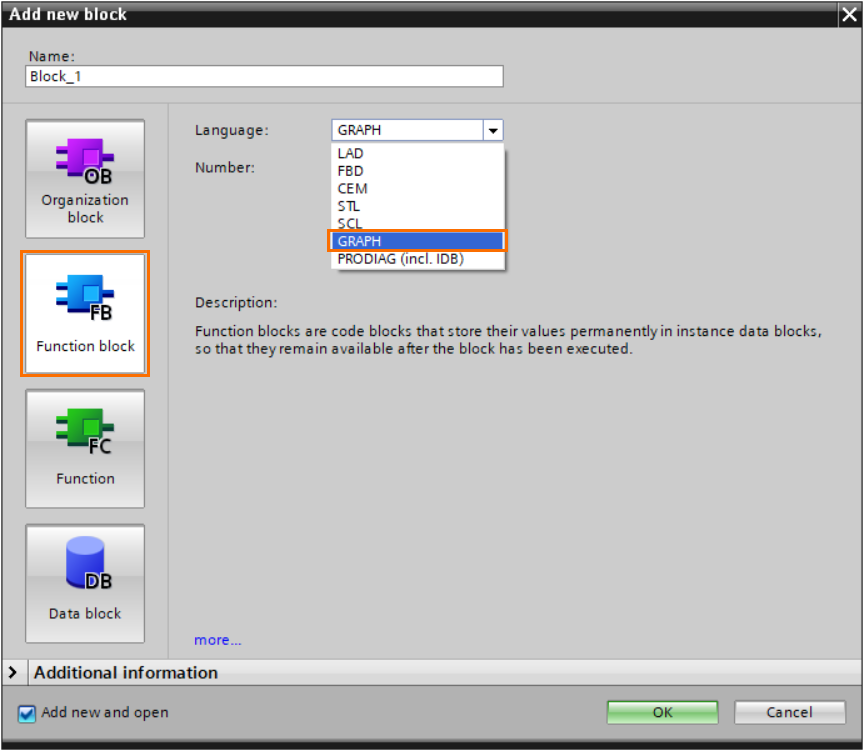
Once the language is selected, give the block a name and click “OK.”
![Figure 1.5 - TIA Portal GRAPH Language | Creating a new Function Block [FB]](https://cdn.prod.website-files.com/63dea6cb95e58cb38bb98cbd/64ee9dd4c3b6732ca1e466cc_SWl5ZA0qZf0rMPo3224DFGfWL6JzvNw5xo9R4mBZGXw6-_bfCARYBH8b9oUHMLxSB5yxgaTKghZdMlzqjBUPCnqn3hB_FQzVBmX7S8_r96wc21cm4jaRfJDoLjUcl_jiARR7ATfAxuJrUS8_AvaNdoY.png)
Basics of the GRAPH language in TIA Portal
We now come to the programming interface of the GRAPH language.
The GRAPH language is how the SFC language (Sequential Function Chart, a.k.a Grafcet) is named in the Siemens environment. The SFC language is a graphical language where you build sequences as successions of Actions/Conditions known as Steps (actions) and Transitions (conditions). Its main purpose is to serve as a graphical representation for designing and implementing sequential control logic in industrial automation applications. In GRAPH programming, control logic is structured as a series of interconnected charts (sequences), with each chart containing graphical elements (steps and transitions). Steps represent specific actions or operations, while transitions define the conditions that lead from one step to another.

- Navigation: All your sequences are displayed here. It also gives a general view of the active sequence.
- Workspace: This is where you assemble steps and transitions. By default, it contains an initial step and a first transition.
- Toolbox: You can find all GRAPH elements here, such as steps, transitions, branches, and endpoints.
- FB interface: As with any other FB block, GRAPH blocks have an interface where you can define the block’s inputs and outputs.
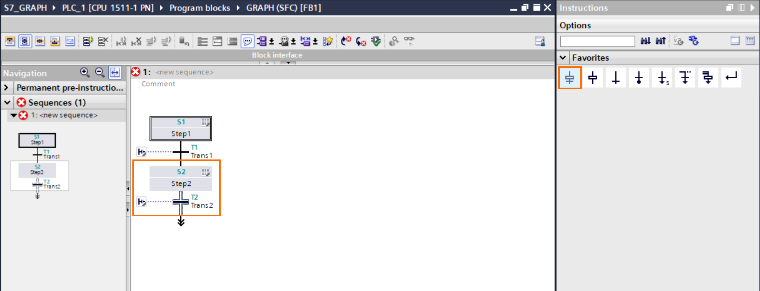
Let’s start adding elements to the sequence. Grab the first element in the toolbox (step and transition) and drop it under the first transition. As its name suggests, this tool allows you to add both a step and a transition at the same time.
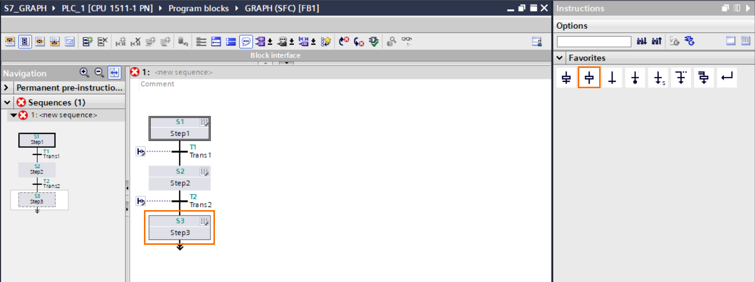
The next element, step, allows you to add a step to the sequence.
The third element, transitions, allows you to add a transition in the sequence.
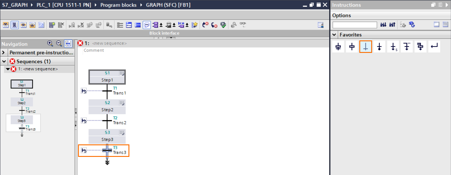
Please note that adding two steps or two transitions in a row is impossible. Each step must be followed and preceded by a transition and vice versa.
Now, let’s have a look at the sequence branching. There are two types of branches:
- Conditional branch: This type of branch is used when you need to define multiple conditional paths like “if X do Y OR else do Z.” It is the equivalent of an OR splitting.
- Simultaneous branch: This type of branch is used when you need to define multiple paths that happen at the same time like “If X do Y AND Z”. It is the equivalent of an AND splitting.
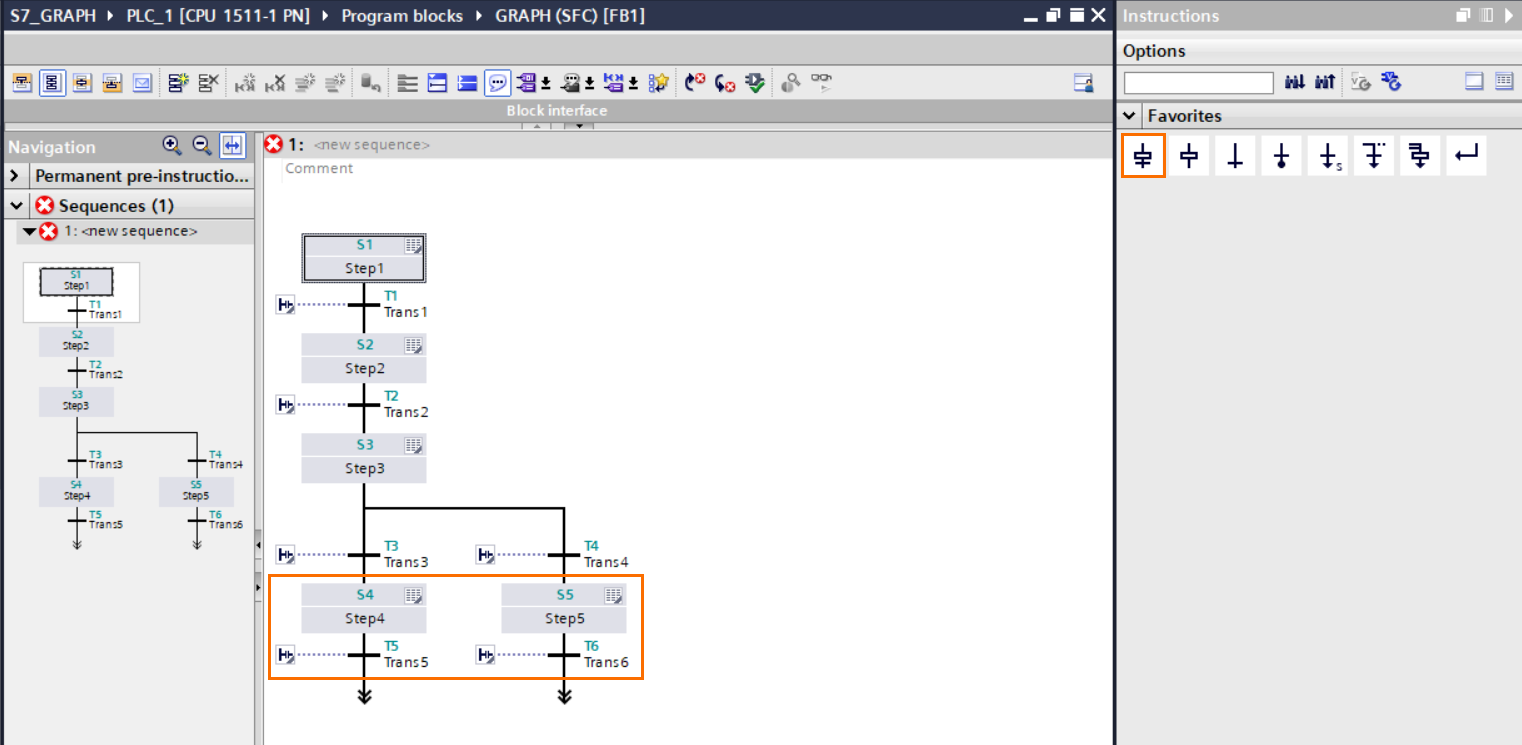
Let’s add a conditional branch. Grab a “branch” element and drop it just before transition 3. A conditional branch can only be added before a transition.
This will open a new branch with a fourth transition. You can interpret this as a logic OR; Once at step 3, if transition 3 is true, it will go to the left path. If transition 4 is true, it will go to the right path.

We can define the following actions in both paths by adding steps and transitions.
If you need to merge two branches at one point to become again a single branch, you can use a “Close branch” element where you need to connect them. Select a “Close branch” element and drag it to the end of the right path (after transition 6).
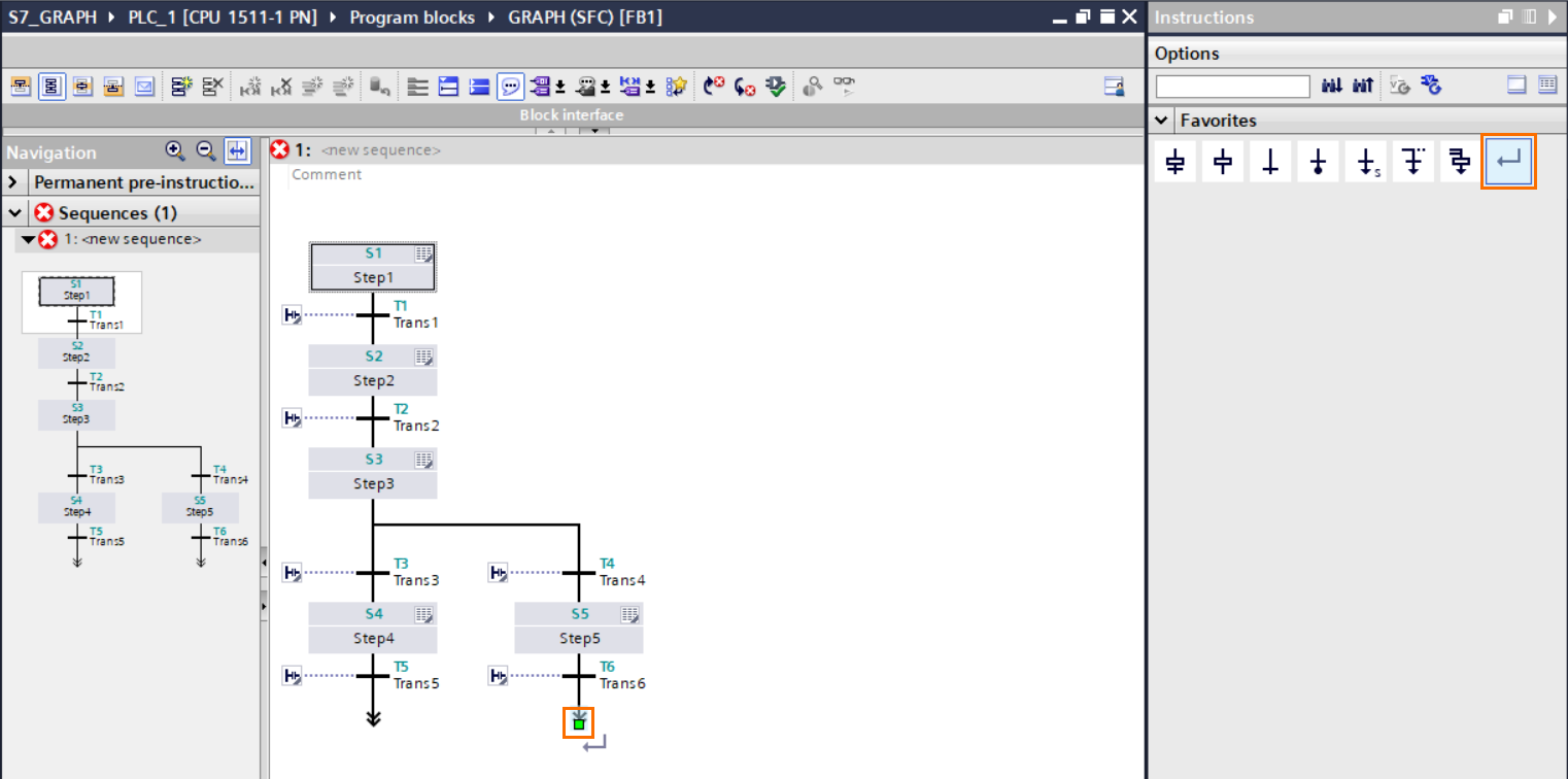
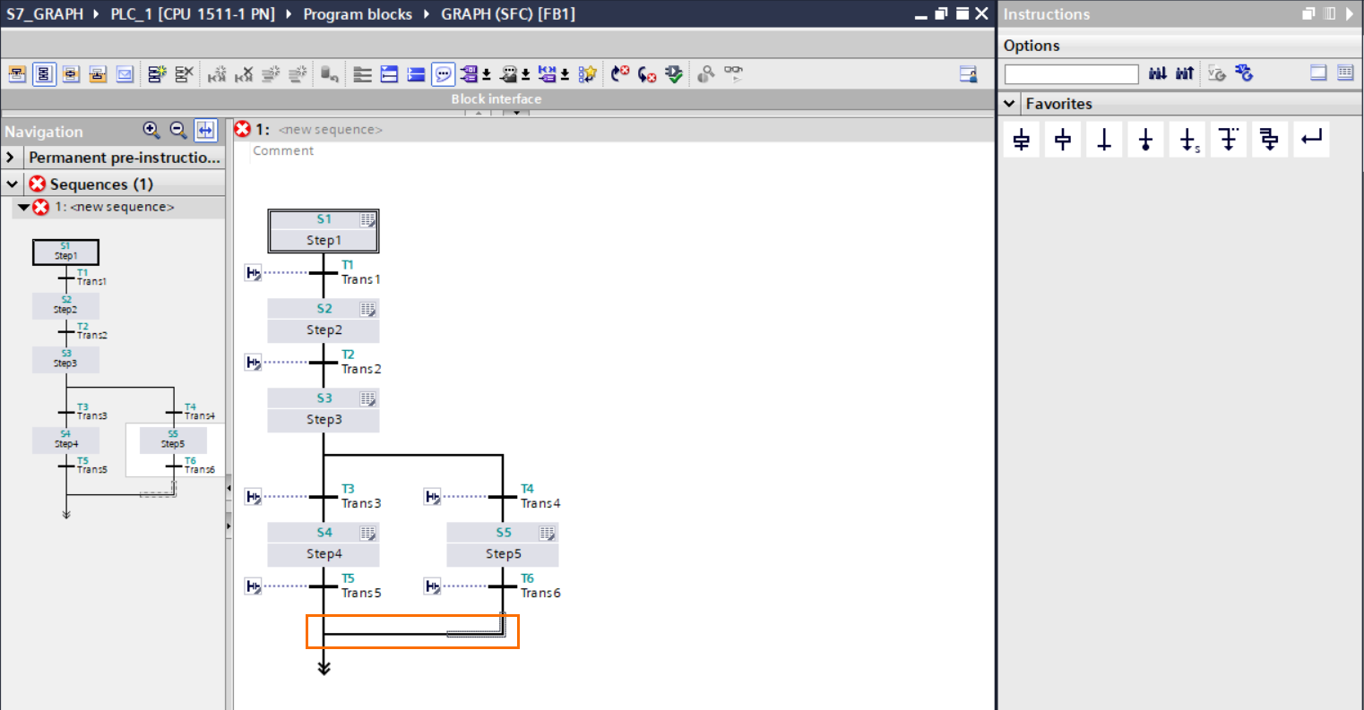
Then, drop it to close the branch and return to a unique branch.
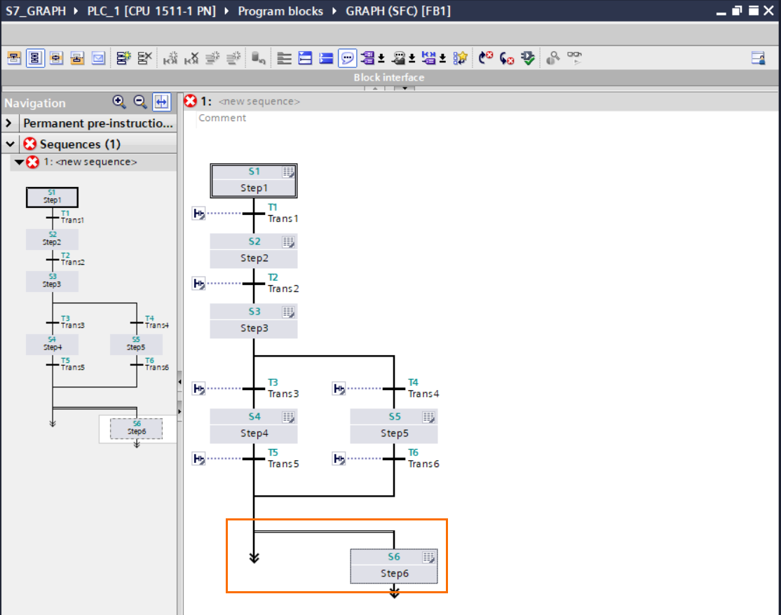
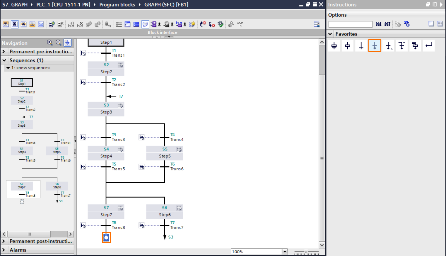
Now, let’s add a simultaneous branch. Select the “Simultaneous branch” element and drag it to the last point of the sequence.
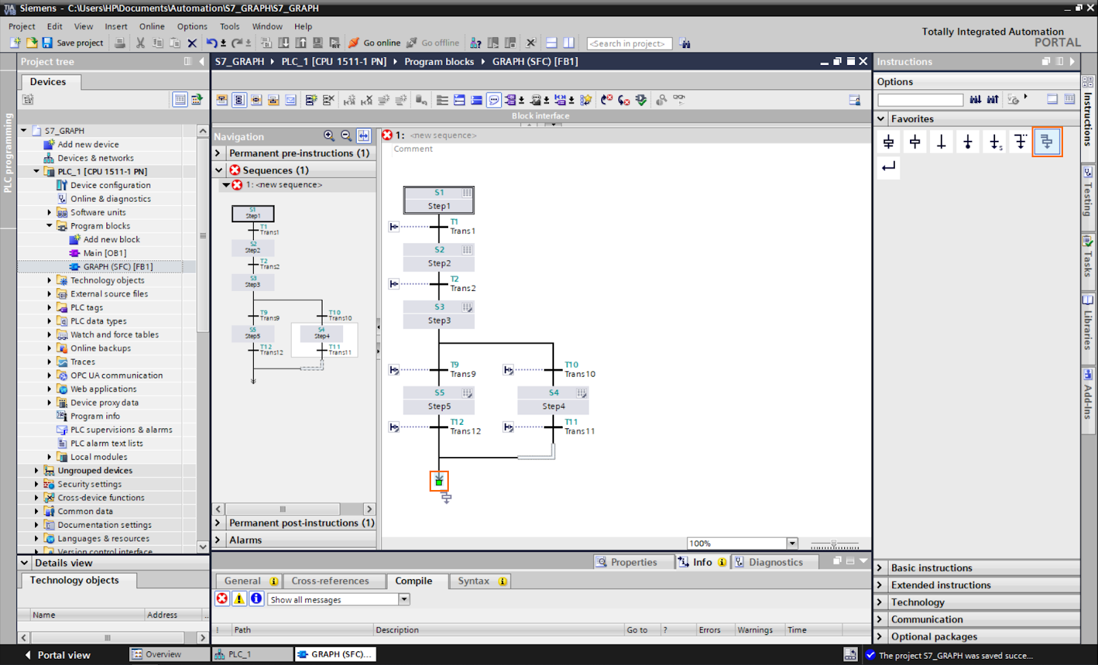
This will create a simultaneous branch. You can distinguish it by the fact that the top line is doubled. It will also automatically create a step in the newly created branch.
You can add the missing steps and transitions to fill the branches.
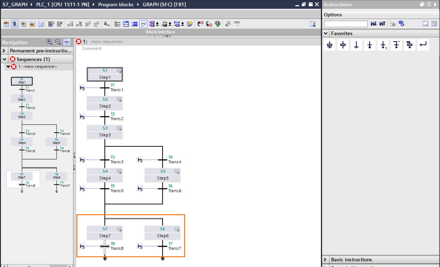
Here, both steps 6 and 7 will be executed at the same time. The simultaneous branch allows you to create a logic AND between multiple paths.
Instead of closing the branch as we did before, we can add an endpoint. There are two types of endpoints:
- Jumps: Allows you to create a loop to return to a previous step.
- End of sequence: Indicates that the sequence ends at this point.
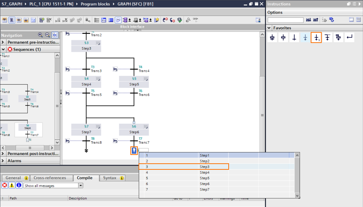
Let’s try to add a jump first. Select the “Jump” element and drag it to the end of the right branch. This will open a small window where you can select the step to jump to. Select step 3.
Jumps are indicated with black arrows indicating where the jump occurs (from T7, to S3).
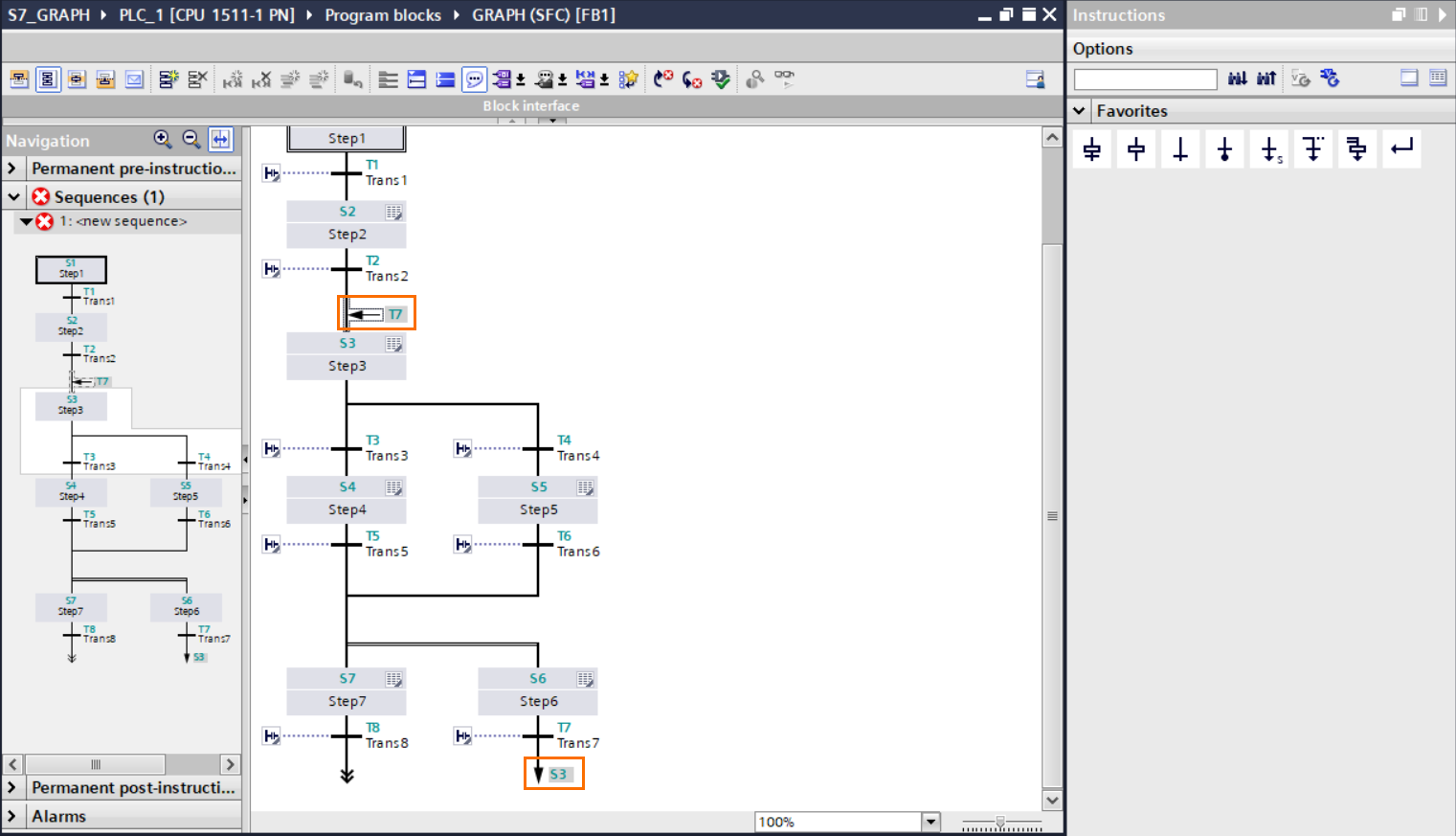
We can add an “end of sequence” element on the left branch. This will indicate that the program stops after transition 8. Select the “end of sequence” element in the toolbox and drag it to the end of the left branch (after transition 8)
Programming steps and transitions
We have covered the basics of creating a GRAPH diagram with its different tools to build complex logic sequences; we can now get a closer look at programming the actions performed in the steps and the transitions’ conditions.
Let’s start with a simple sequence containing 2 steps and transitions and a jump to step 1 at the end. After that, click on the “Single-step view” button to access the content of the steps/transitions.
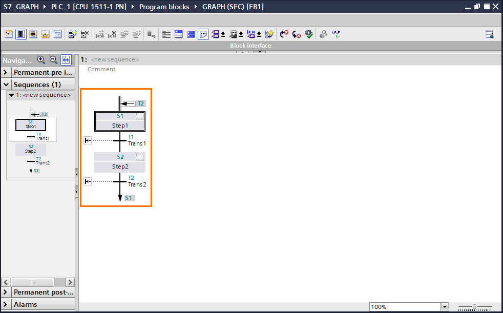
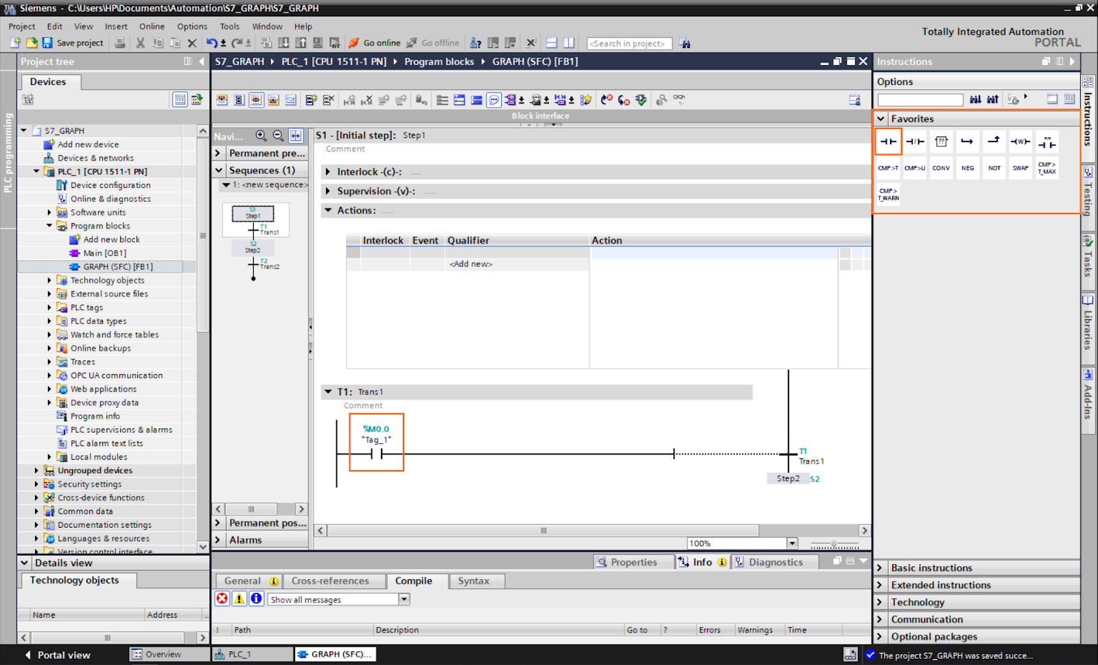
The single-step view mode always displays a step/transition pair (Here for example it displays step 1 and transition 1). You can select the desired step/transition pair to edit in the sequences section. Here, you can edit the actions performed in the selected step in the “Actions” section and define the conditions to be fulfilled to activate the transition in the bottom section.

For now, we will keep step 1 empty. Let’s first focus on the first transition. On the left side of the screen, you will find instructions allowing you to build complex logic operations in the instructions section. A boolean result always commands the transition, meaning only boolean logic operations and comparisons are allowed. By default, the transition programming uses the ladder language.
Let’s try adding a simple boolean interrogation. Select a NO contact instruction and drag it to the transition section. Once done, define a tag and add it to it.
Now select the step 2/transition 2 pair in the sequences section.
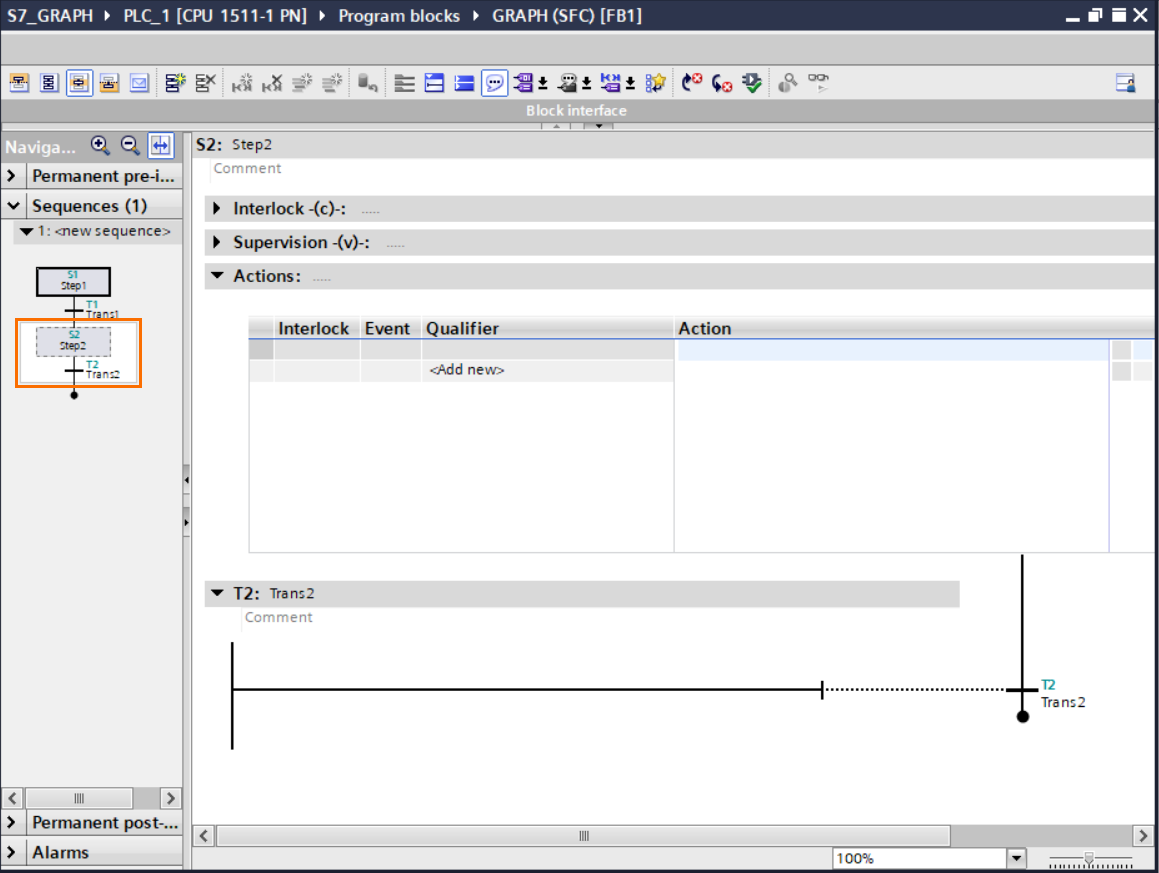
We will now define the actions of step 2. Many possible actions can be performed, such as set, reset, count up, count down, timers, affectations…etc. These types are called qualifiers; you can access the list by clicking on the arrow button in the “Qualifier” section.
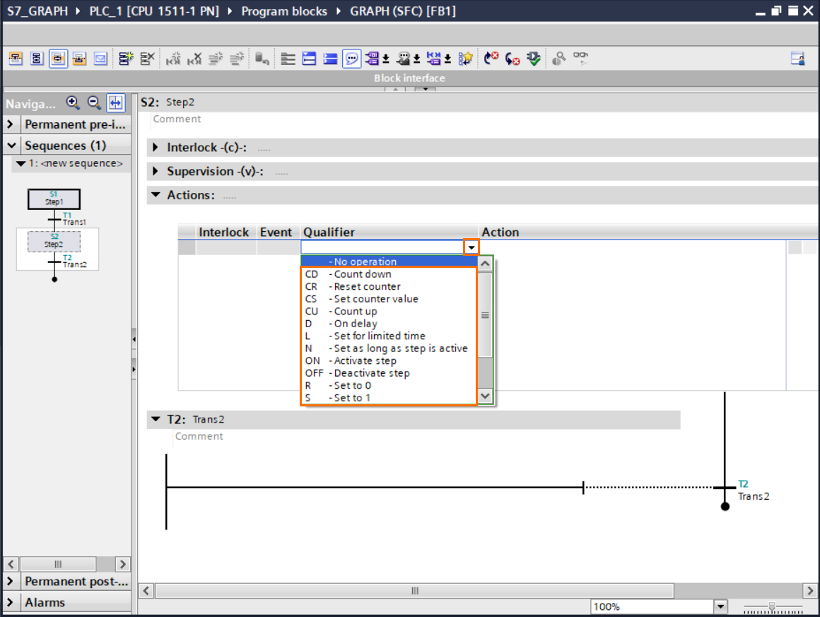
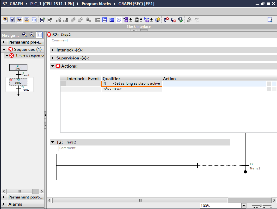
Select the “N - Set as long as step is active” in the qualifiers list. This sets a tag to 1 while the step is active. When the next transition is true, the step is disabled, resetting the selected tag.
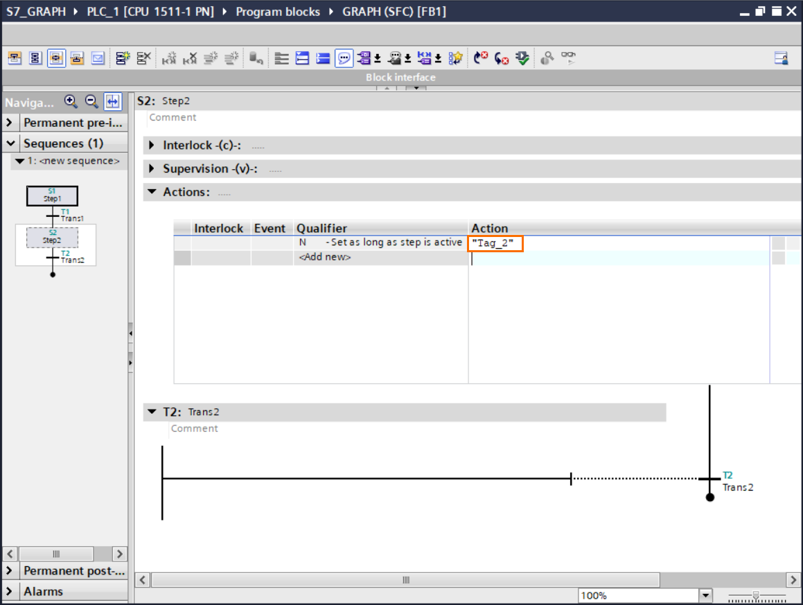
In the “Action” section, you can define the tag or address on which the action will be performed.
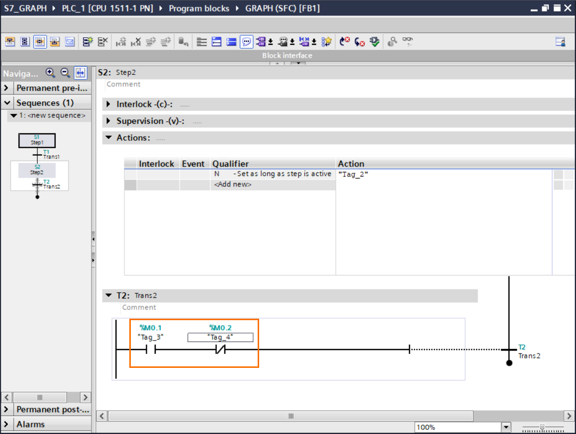
Now, let’s move to transition 2. You can add multiple instructions to build more complex conditions in which the final result will command the transition state. Add a NO contact and an NC contact with tags.
You can also add multiple actions in a step. Add a “S - Set to 1” action with another tag. Once the step is activated, it will also set to 1 permanently the selected tag (Tag_5).

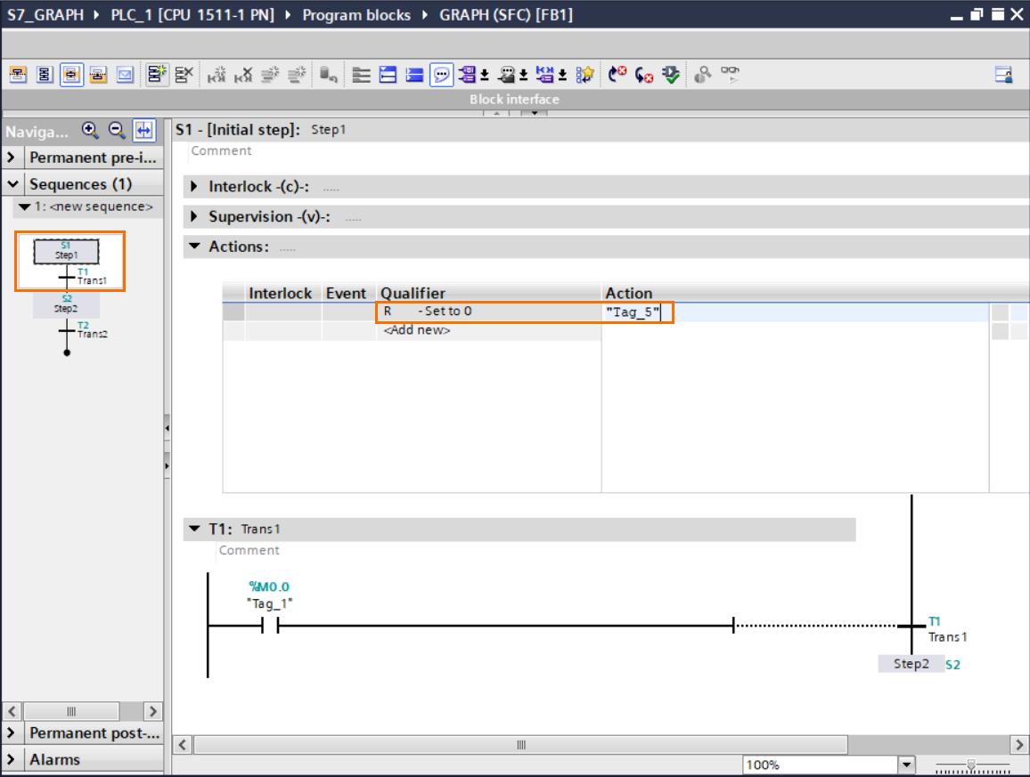
After that, we can return to step 1 to permanently reset the tag we set to 1. Select step 1 in the sequence view and add an “R - Set to 0” with the Tag_5. This will reset to 0 the tag when we return to step 1.
Executing a program in the GRAPH language
When we are done programming, we can test the execution of the program using a simulation. Open PLCSim and load the program into it. Don’t forget to call the FB in the main program. We will use a watch table to interact with the tags we used in the program.
- The program starts in the initial step (Step 1) and waits for transition 1 to be true before going to Step 2.
- Transition 1 is controlled with Tag_1. If it’s true, we move to the next step
- The program goes to Step 2, setting Tag_2 and Tag_5 to 1.
- Transition 2 is controlled by the logic result of Tag_3 and the invert of Tag_4. This means that Tag_3 must be at 1 and Tag_4 at 0 to enable the transition.
- Leaving Step 2 resets Tag_2 and going back to Step 1 resets Tag_5.
Conclusion
In this tutorial, you learned how to leverage the GRAPH language within Siemens' TIA Portal to create sophisticated control logic for industrial automation. Starting with the basics, you explored the process of project creation, device setup, and function block addition. Through a series of intuitive steps, you built complex control sequences using Steps and Transitions, implemented conditional and simultaneous branches, and employed endpoints to fine-tune sequence behavior. Furthermore, you gained insights into programming actions within Steps and defining conditions for Transitions, ensuring the logic operates seamlessly in real-world scenarios.
In industrial automation, the GRAPH (SFC) language stands as an indispensable tool for engineers and automation professionals. Its primary purpose is to provide a graphical means of representing and implementing sequential control logic. This language allows for the creation of logical sequences, with Steps embodying actions and Transitions embodying conditions that dictate the flow of control. The ability to design and execute such control logic is pivotal in a wide range of industrial applications, from manufacturing processes to complex machinery control. The GRAPH language's visual nature enhances the comprehensibility of automation workflows, facilitating efficient troubleshooting, maintenance, and modification of control sequences, and ultimately contributing to the advancement of industrial automation systems.
