Arduino Opta | Downloading & Installing Software / Tools, Configuring IDE, and Running Basic Sketch

Introduction to Arduino Opta
Arduino, a popular embedded systems platform, has recently released their new hardware in a partnership with finder - Arduino Opta. For those that may not know, I have extensive experience with Arduino. Before getting started with industrial automation and controls, I’ve had a popular Arduino programming YouTube channel - https://www.youtube.com/@EEEnthusiast On this channel, some of the most popular Arduino tutorials reached over 500,000 views and helped thousands of hundreds of engineers create projects using the platform. Furthermore, I’ve also worked on a number of projects that used Arduino software on a standalone ATmega328P-PU microcontroller (Arduino Uno core).
The Opta offers three variations of the hardware - Opta Lite, Opta RS485, and Opta WiFi

As the names suggest, the RS485 adds RS485 capability onto the base model, and the WiFi model adds WiFi capabilities onto the RS485 model. At this time, you can purchase the controllers for the following price:
Arduino Opta Lite - $146.40
Arduino Opta RS485 - $160.80
Arduino Opta WiFi - $193.20
However, all of the models are currently “SOLD OUT”.
The Main Selling Points of the Arduino Opta Platform
Arduino revolutionized embedded systems with the release of their Arduino Uno platform. For those that haven’t programmed an ATmega microcontroller without the Arduino IDE in C / Assembly, the different is night and day. Arduino streamlined the entire development process:
- The hardware eliminated the need for PCB design and complex setup process for getting signals in / out of the board.
- The software made it easy to create sketches that took care of back-end programming and made it intuitive for the user. Furthermore, it opened up the world to an open source collaborative environment where sketches and libraries could be easily shared between users.
The Opta promises to bring the same to the industrial world - an open development environment that supports the Arduino programming suite, as well as the newly added PLC IDE that supports IEC 61131-3 PLC languages that most control systems engineers already are familiar with. Based on my understanding, there’s an intent to bridge the gap between embedded systems and control systems engineering.
Arduino Opta Key Benefits
- Can be programmed using “classic” Arduino IDE in C / assembly or the new PLC IDE using IEC 61131-3 PLC languages.
- Support for Fieldbus and Modbus protocols.
- WiFi (only 1 model) support.
- Arduino Cloud support / integration.
- Rugged design with dinrail mount.
Arduino Opta Specifications
In this section, let’s explore the specifications of the Arduino Opta. Note that they can all be found in a “difficult to read” format in the datasheet of the hardware.
As mentioned above, there are three variations of the Arduino Opta controller - Lite, RS485, and WiFi. Here are their basic communication specifications:
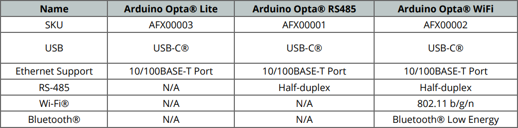
All controllers have the following specifications:
Input supply voltage range - 12 to 24 VDC
Inputs - 8x Digital or Analog
Outputs - 4x Relay
Processor - Dual-core ST STM32H747XI Processor
Program Memory - 1 MB of RAM
Flash Memory - 2 MB
Arduino Opta Inputs
As mentioned in the datasheet, the Arduino Opta has configurable input ports. They can be programmatically set to digital or analog inputs. For the digital setting, the Arduino will read either a LOW or HIGH signal; for the analog setting, the Arduino will read a voltage between 0 and 10 VDC.
Arduino Opta Outputs
The Opta has 4 Normally Opened relays to drive outputs. Each relay is rated at 10A of current with a maximum voltage of 250 VAC.
Getting Started with Arduino Opta
At the SolisPLC headquarters we’ve managed to secure the Opta RS485 version before it was sold out. In this section, our goal is to provide an overview of the “getting started” process so that you can easily install the right tools and connect to your controller!
The Arduino landcase has quickly become confusing for a first time user. We’ll cover both ways for you to get started with the Arduino Opta below.
Option 1 - Using the Classic Arduino IDE
Step 1 - IDE Downloads
If you wish to program the Opta using the traditional Arduino programming interface, you’ll need to download the Arduino 1 or 2 IDE.
We’ve tested ours with the Arduino IDE 2.0.4
Download Here - Arduino IDE
Step 2 - Tooling Downloads
Both IDEs require the user to download a tooling package for the Arduino Opta family.
For the Arduino IDE v2.0.4, you’ll need to follow the instructions:
- Install the IDE.
- Launch the IDE.
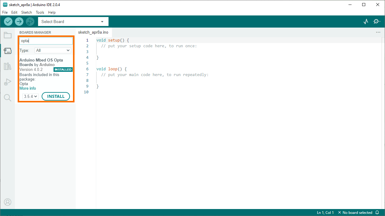
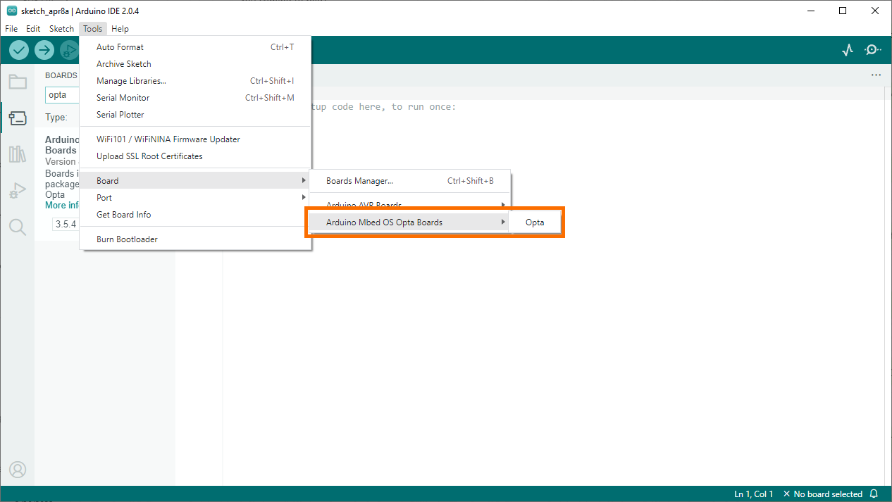
- Select “Tools” > “Board” > “Boards Manager”

- Search for “opta”
- Install “Arduino Mbed OS Opta Boards by Arduino”
Step 3 - Powering & Connecting the Opta
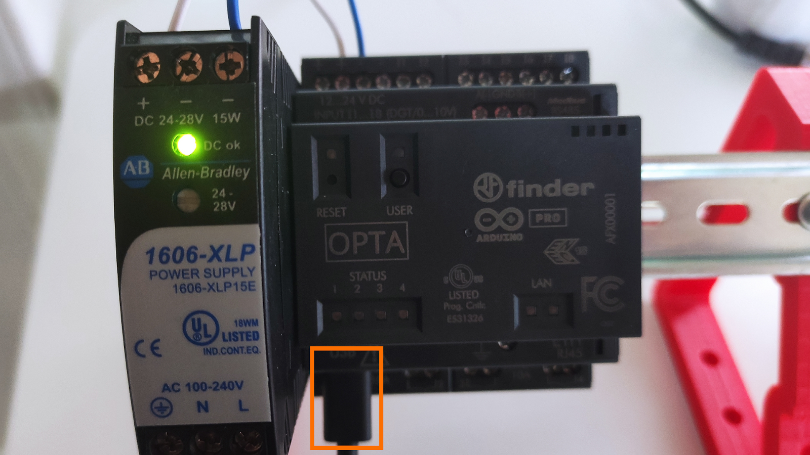
We recommend using a 1A power supply that provides 24VDC to power the Opta. It’s important to note that 24VDC is the industrial standard which isn’t something you’d see on the traditional Arduino boards. Unlike the Arduino Uno which is powered by the USB cable, the Opta requires a power supply to be tied to the + and - terminals on the top left corner.

Next, connect your computer to the Opta via the USB-C port on the bottom left corner.
Step 4 - Arduino IDE Connection & Sketch Download
At this point, we’re ready to connect to the controller and download our first sketch. If you’ve installed the IDE and tooling correctly, you’ll see an option for the Opta board. You need to select the Opta under the following dropdown.
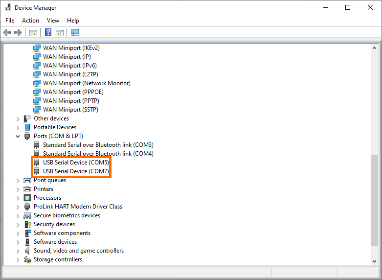
Next, we need to make sure that we’re connecting to the port that is connected to the Opta from our computer. To do this, you’ll need to launch Device Manager in Windows. Under “Ports” you should see one or two ports that are associated with the Arduino Opto. If you aren’t sure which ports fall under this category, unplug the USB, wait a few seconds, and plug it back in.
Note: in the PLC IDE section you’ll install tooling that “creates” the second port as part of the initial firmware flash. Until then, you should only see one port for the Opta. If you’ve gone through the tooling installation for the PLC IDE, you’ll see two of these ports.
Once you confirm the port, you need to select it in the Arduino IDE under “Tools” > “Port”
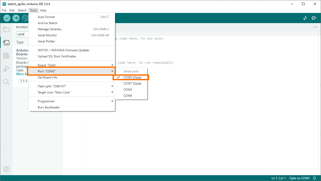
Note that once you select your board and port, they should be displayed at the bottom right corner of the IDE. Based on the selections we’ve made in this tutorial, the IDE displays Opta on COM5.
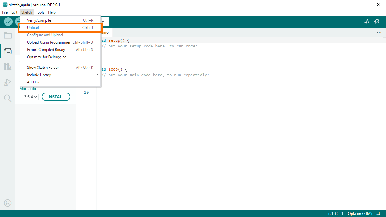
We can copy & paste the sketch written by Arduino as a test of the controller.
Use one of the several ways to Upload the sketch to the Opta (Using the arrow icon from the IDE, using the Upload button from the “Sketch” menu, or using the Ctrl + U shortcut)
Step 5 - Final Result
If everything goes well, you should receive a confirmation message from the Arduino IDE that your project has been successfully downloaded and the sketch we’ve loaded onto the Opta should now let you press the User push button to achieve a “scrolling” effect of the LEDs as shown below:

Option 2 - Using the Arduino PLC IDE
Step 1 - IDE Download & Install
If you wish to program the Opta using the PLC Programming Languages, you’ll need to download a separate IDE - Arduino PLC IDE.
We’ve tested ours with the Arduino PLC IDE 1.0.3.1
Download Here - Arduino IDE (Scroll down the same page)
Install the IDE.
Step 2 - Tooling Downloads
Both IDEs require the user to download a tooling package for the Arduino Opta family.
For the Arduino PLC IDE v2.0.4, you’ll need to follow the instructions:
- Download the Tools under the same download page. Note: you won’t be able to program the Opta through the PLC IDE if you skip this step.

- Double click the file to install.
Step 3 - Powering & Connecting the Opta
Follow the same instructions as we’ve outlined above. Connect 24VDC Power and a USB cable to the Arduino Opta.
Step 4 - Arduino IDE Connection & Sketch Download
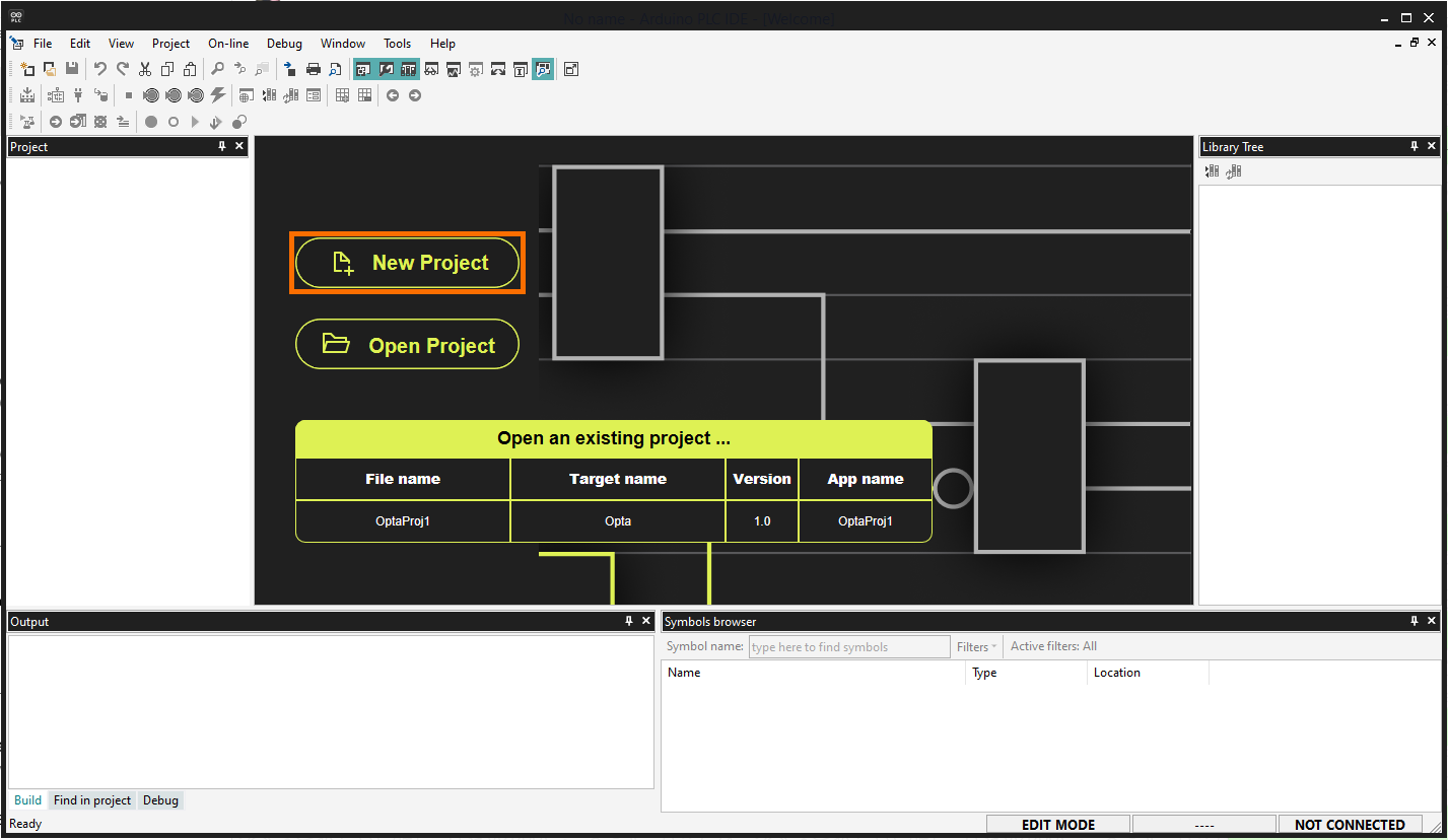
Launch the Arduino PLC IDE and create a new project.
On the main page of the project, in the “Other” section, choose the same port as we had chosen in the previous section. Press on “Download”
At this point, the IDE will install the firmware needed for the controller.
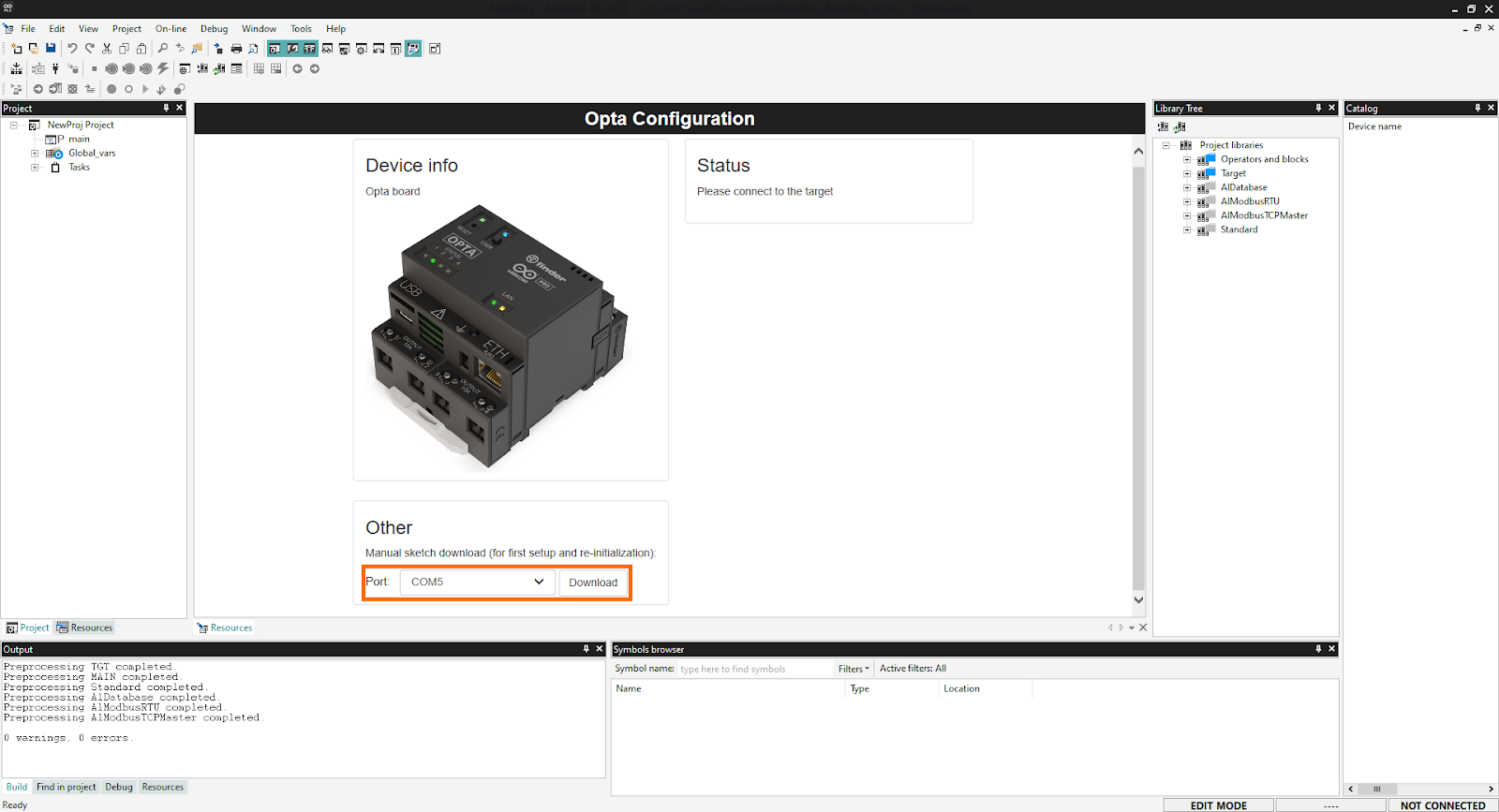
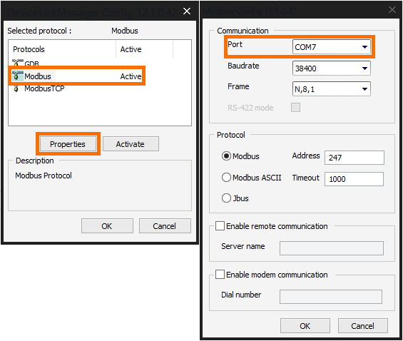
Under “On-Line” > “Set-Up Communications” you’ll find a menu that has connection drivers. You need to select the “second” port that is listed for the Opta under your Windows Device Manager. In our case, the initial port was COM5 while the port we’ve set here is COM7 as shown in the table below.
At this point, we’re ready to connect. Select “On-Line” > “Connect”. If everything goes well, you should see the following screen with the available interfaces listed for your specific device and a status of “CONNECTED” in the bottom right corner of the IDE:
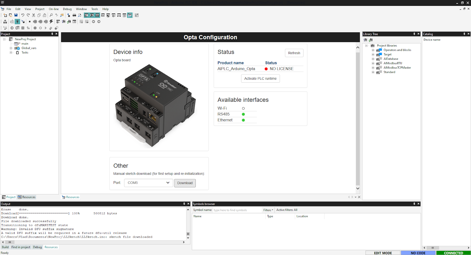
Note that the Opta comes with a license, so you simply need to press on the “Activate PLC runtime” to enable the program you’ve created.
Conclusion on Arduino Opta
At first glance, the Arduino Opta isn’t a solid offer for the industrial automation space. The “more mature” low-price platforms such as Siemens Logo, Automation Direct, Allen Bradley Micro800, Opto 22, Phoenix Contact, and a few others are much more capable at this time. The only advantage we see on the Arduino side is a strong userbase it managed to gather over the years. That being said, the Opta does feature an “extension” port which may be used for additional modules that will put the Arduino Opta at an advantage over the competition. Only time will tell.
