Balanced Load Distribution in Multi-Motor Systems Using Siemens PLC

Introduction
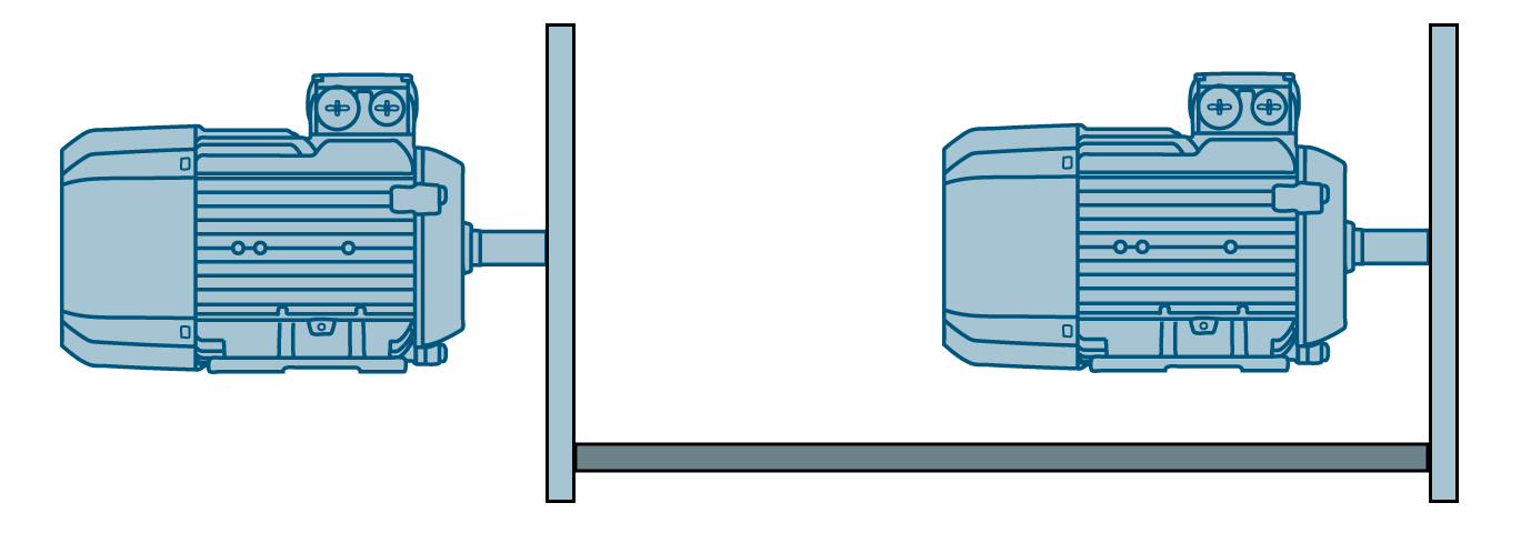
If you're using several motors at once, it's necessary to distribute the mechanical load evenly among them to ensure proper functioning. When you don't balance the load during motor control, they can end up fighting each other and even begin oscillating. When dealing with an imbalanced load, their temperature could spike, or motors may trip due to hitting their maximum torque. You require a solid mechanical connection to spread the load among the motors. So, the deal is that the motors must either work with the same gearbox or be connected through a shaft.
If you check out Figure 1.2, you'll see a discrepancy in the actual torque values of both motors. Even with the mechanical coupling maintaining the same speed setpoint, each motor deals with its load.

Look at Figure 1.3! The torque values match, and both motors cooperate to split and handle the load evenly.
Prerequisites
What you will need to follow along with this tutorial:
- You need to install the TIA Portal software on your personal computer. Although this tutorial refers to version 18, rest assured that other versions of the TIA Portal will work just fine.
- How to apply technology objects for controlling purposes.
Load Balancing Principle
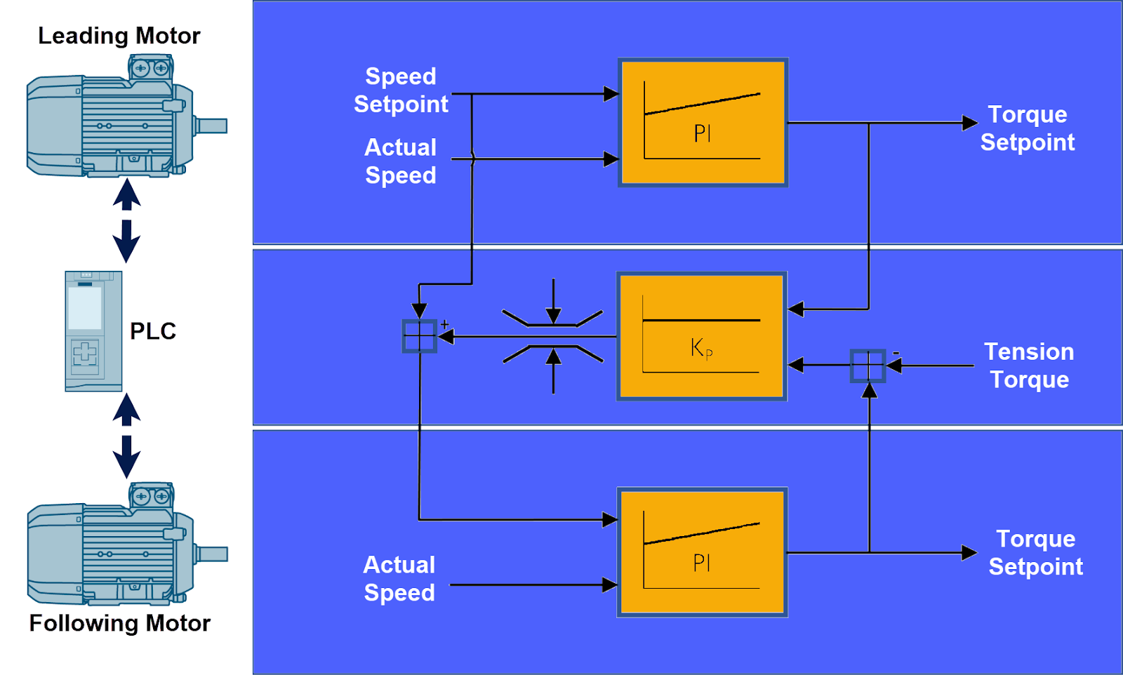
The idea behind load balancing, as explained in this tutorial, is to compare the torque setpoints of motors meant to work together. Here, the motors team up in a leading-following setup, where a single motor leads while multiple motors can follow. On the PLC side, there's a load balancing controller for every following motor, assessing torque setpoint variations from its leading motor. The assessment produces an output value, which serves as an additional speed reference for the following motor, promoting an equal workload distribution. For load balancing to be effective, it's as simple as having the leading and following motor(s) set to the same speed. To guarantee this, use one position control for both motors and share the speed setpoint of the leading motor with its associated following motor(s).
Commissioning
The "LLoadBal" library is created particularly for S7-1500 PLCs, allowing load distribution among two or multiple motors. You can download this library from here.
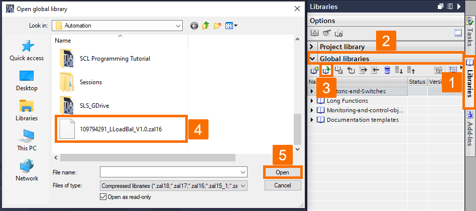
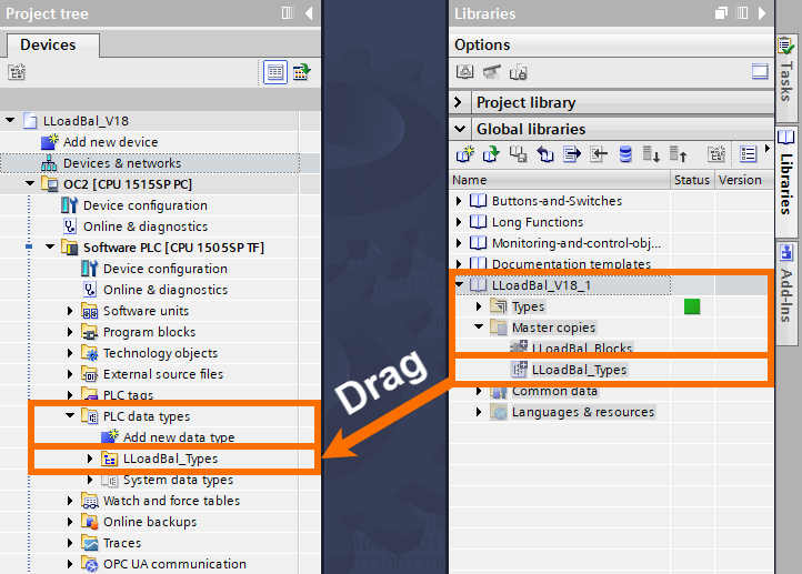
In the TIA Portal, go to the right-hand side and open the "Libraries" task card. From there, head to the "Global Libraries" tab. Then, locate and open up the "LLoadBal" library.
Insert the program blocks of the library by dragging and dropping the "LLoadBal_Types" group from "Master copies" into the "PLC data types" folder of the S7-1500 PLC.
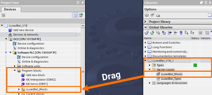
Insert the data types of the library by dragging and dropping the "LLoadBal_Blocks" group from "Master copies" into the "Program blocks" folder of the S7-1500 PLC.
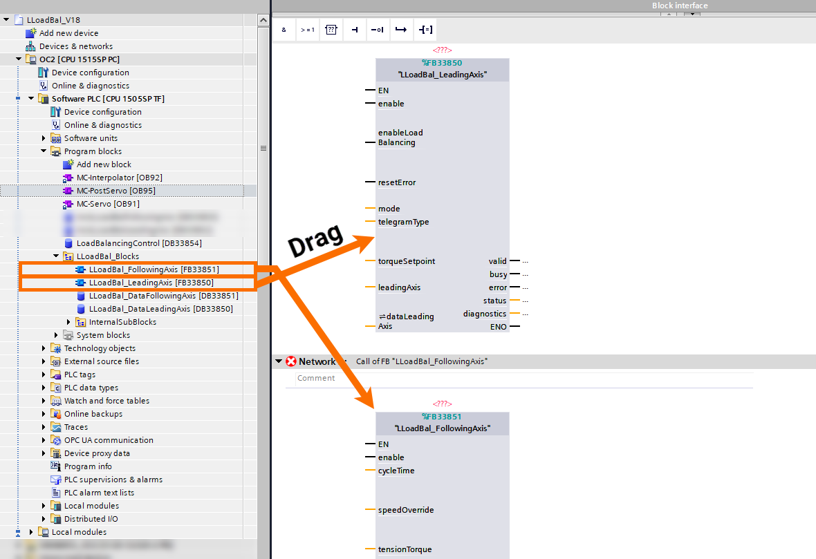
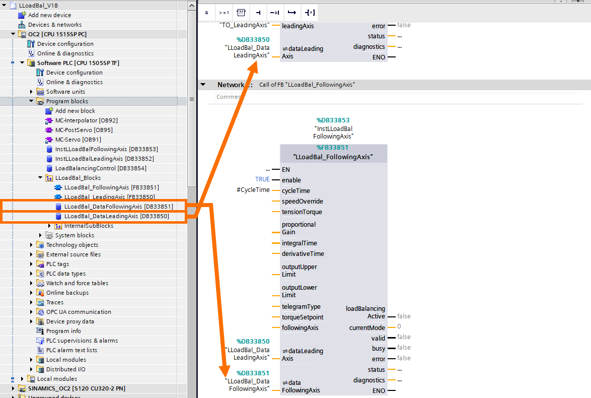
Within the MC-PostServo organization block (OB95), you must cyclically call the "LLoadBal_LeadingAxis" and "LLoadBal_FollowingAxis" function blocks for them to work correctly.
Ensure that the OB95 is added to the "Program blocks" folder of the S7-1500 PLC if it is not included in the project already.

Insert the "LLoadBal_LeadingAxis" function block into the first available network (Network 1) within the OB95 by dragging and dropping it. To include the "LLoadBal_FollowingAxis" function block, follow the same process.
After adding the required function blocks, ensure that a separate instance needs to be created for each one. To get it done, right-click on the function block in the given network, select "Create Instance," provide a unique name, and confirm your decision.

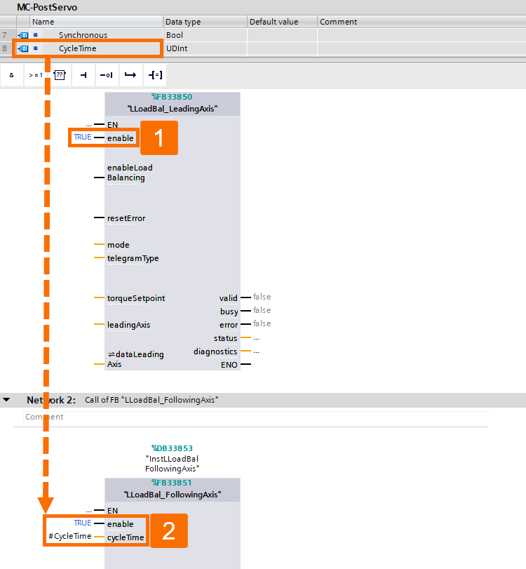
When you send a (static) TRUE signal to the "enable" input, the given function block becomes enabled. The "LLoadBal_FollowingAxis" function block requires knowledge of the cycle time it is called with for its internal functioning. So, the MC-PostServo organization block offers this info in the start info variable "#CycleTime," which you need to assign to the function block's input called "cycleTime."
It's necessary to assign the technology object of the leading axis to the "LeadingAxis" input of the "LLoadBal_LeadingAxis" function block. Furthermore, the "FollowingAxis" input of the "LLoadBal_FollowingAxis" function block should receive the technology object of the following axis.

Both function blocks and their axes are linked using the "LLoadBal_DataLeadingAxis" data structure. Assign it to the "dataLeadingAxis" inputs of both the "LLoadBal_LeadingAxis" and "LLoadBal_FollowingAxis" function blocks.
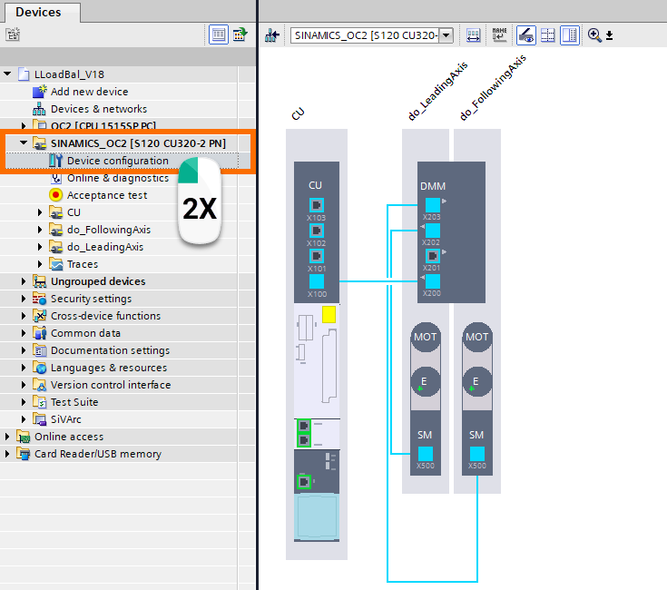
Since the load balancing relies on comparing the torque setpoints of the motors that are supposed to work simultaneously, the setpoint values need to be available in the PLC for further handling. To make this work, you need to expand the specific drive telegram with an extra actual value. While you are still in the TIA Portal, find the device configuration for the SINAMICS control unit and open it up.
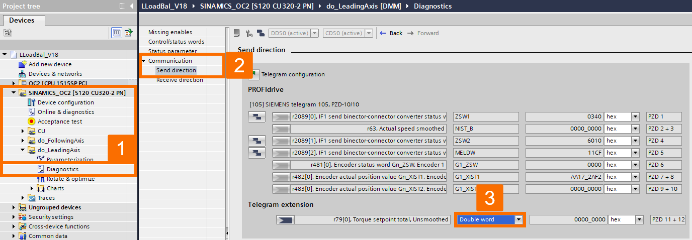
Go into the control unit properties, locate the "Telegram Configuration" option, and include a free telegram (actual value) in both the leading DO (Drive Object) and the following DO that is part of the load balancing process. Make the free telegram two words in length. If required, you can optionally modify the telegram's starting address.

Combine the two words added before into a double word within the "Diagnostics" overview of the specific DO (Drive Object).
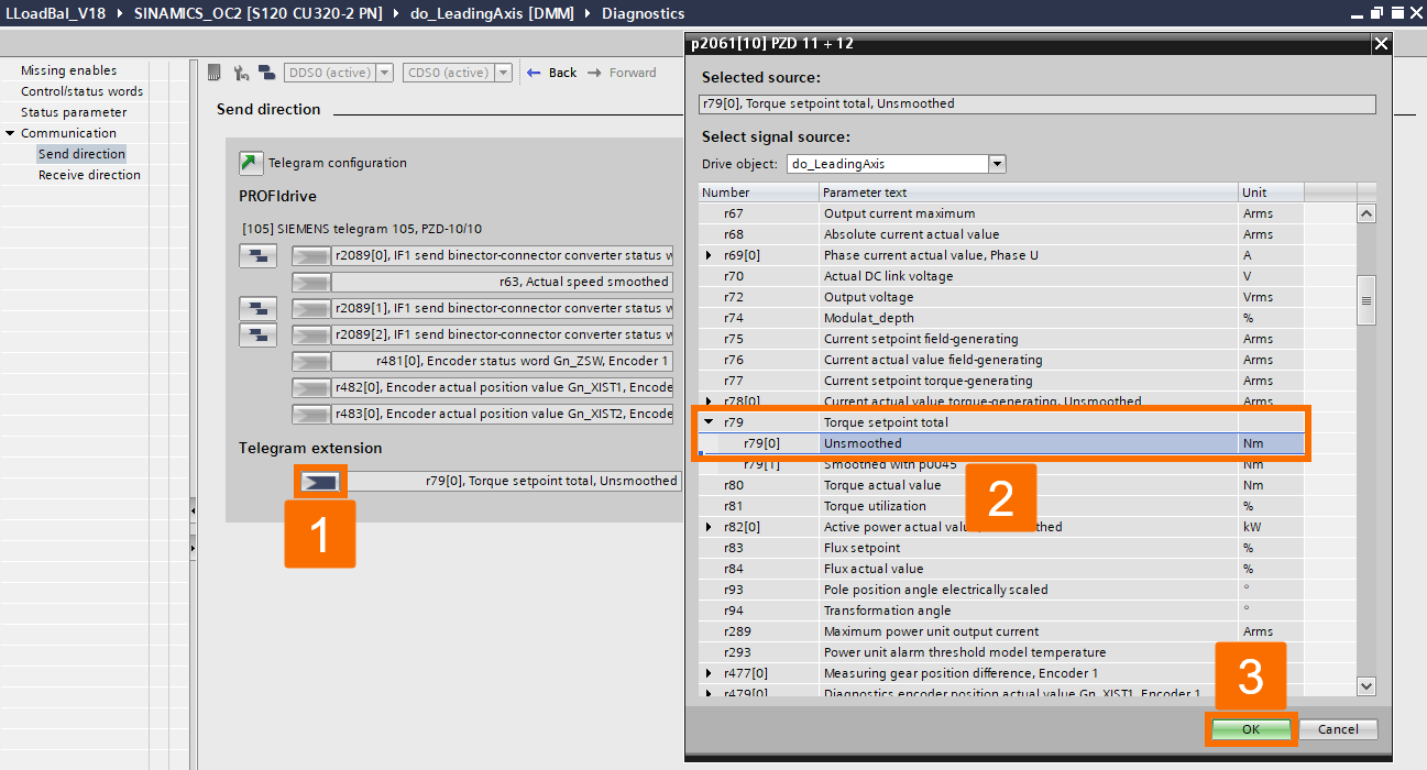
Next, you need to connect the double word to parameter r79[0], which is the "Torque setpoint total, Unsmoothed," of the specific DO (Drive Object).
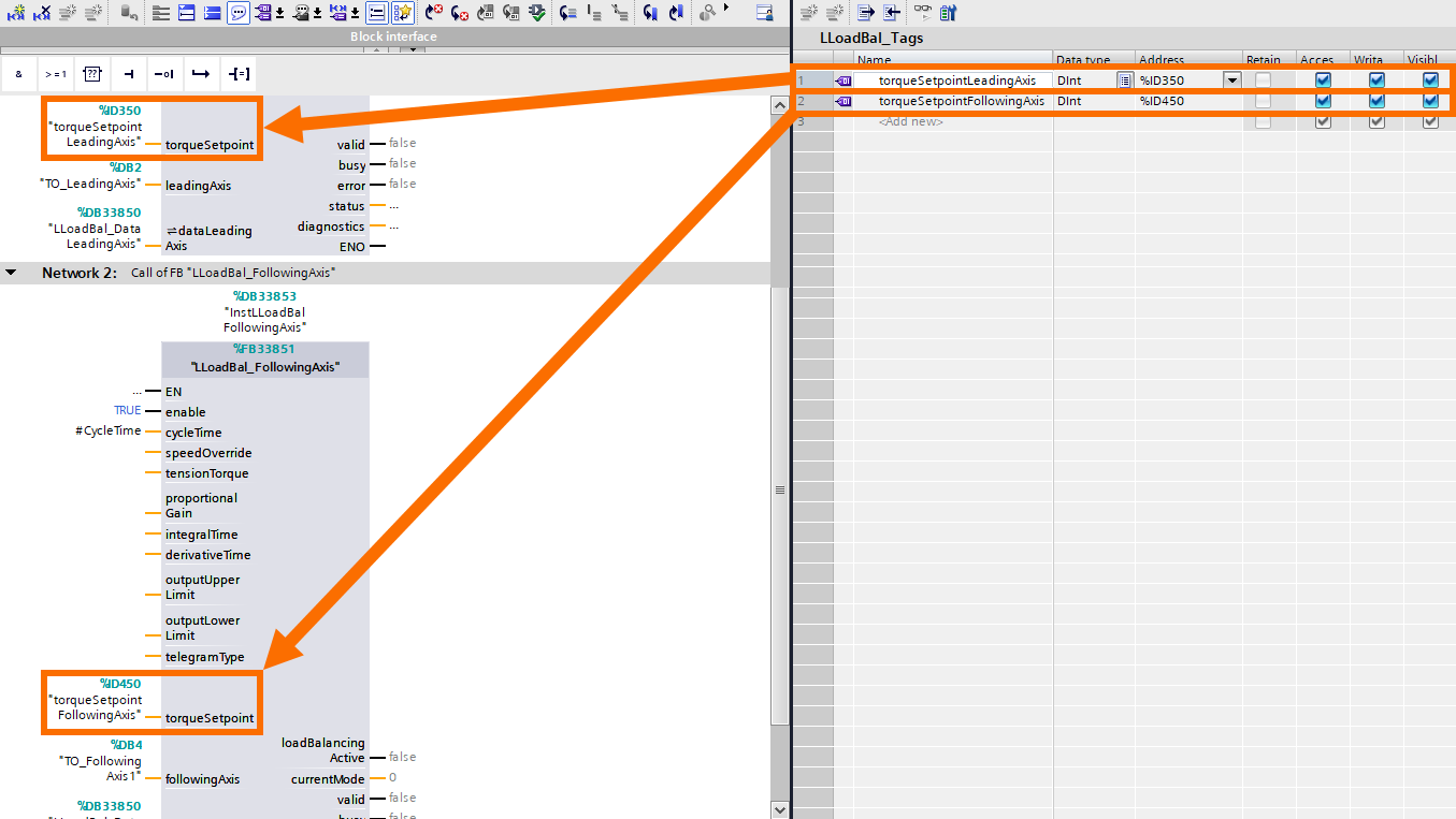
To retrieve the values of torque setpoint through the PLC program, under the "PLC tags" folder, make sure you add a PLC tag for each value, using the starting address from the free telegram you included in the control unit's device configuration earlier. Change the PLC tags' data type to "Dint" (Double Integer).

It is required to connect the PLC tags to the "torqueSetpoint" input of that specific instance of the "LLoadBal_LeadingAxis" and "LLoadBal_FollowingAxis" function blocks in the MC-PostServo organization block (OB95).
Applying Load Balancing
Changing load balancing settings or mode is only possible when the leading axis is not in motion. When the leading axis is in motion, tweaking the input state won't impact how the function block is currently running. But here's the deal: once the leading axis stops moving, any changes you make to the input will kick in immediately.
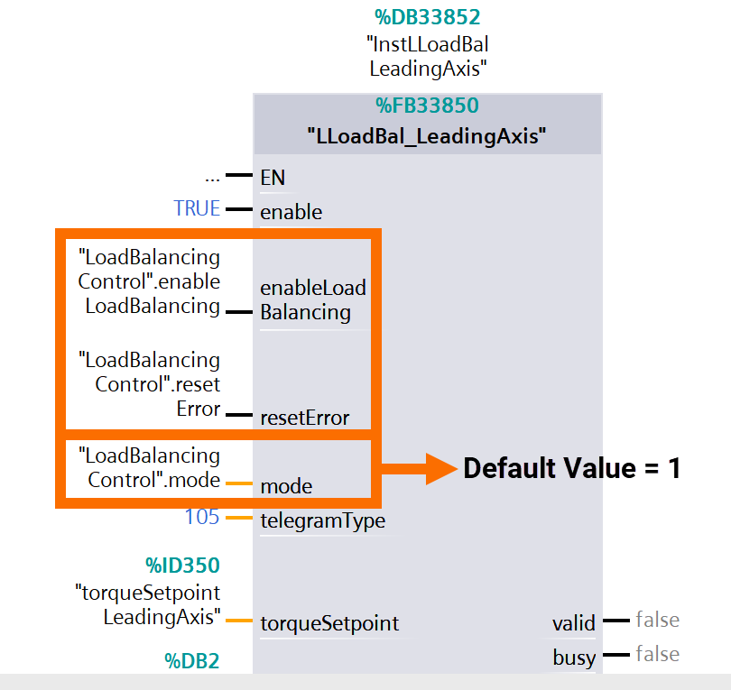
You can activate/deactivate it by using the "enableLoadBalancing" input. So, based on the mode you set using the "mode" input (default value = 1), all following axis function blocks connected to the specific leading will be pushed to switch to that mode.
To clear any errors in the leading axis function block and its assigned function blocks of the following axis, you'll need to activate the "resetError" input with a rising edge.
If the specific following axis has load balancing activated, you'll notice it through the "loadBalancingActive" output of the following axis function block. Load balancing comes into play when you've got the proper mode (in other words, "mode" = 1), set a proportional gain > 0.0, cleared all errors, and enabled both the leading and following axes.

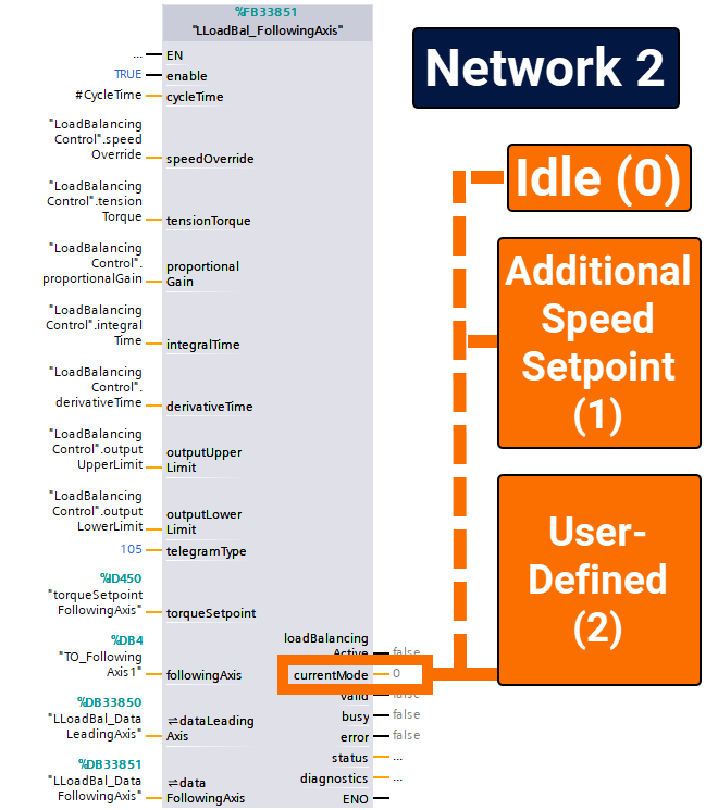
The "CurrentMode" output will display the currently active mode in the function block of the following axis.
Idle ("CurrentMode" = 0): The function block stays put until it receives a command to switch to a different mode. Load balancing is switched off. You'll enter this mode if load balancing is turned off (when "EnableLoadBalancing" is FALSE), the mode is set to "Idle" ("mode" = 0), or there's an error ("error" = TRUE) in the function block of the leading axis.
Additional speed setpoint ("CurrentMode" = 1): When load balancing is enabled ("loadBalancingActive" = TRUE), the setpoints for the leading axis are shared with the specific following axis, and an extra speed setpoint is computed based on differences in values of torque setpoint between the leading and following axes. This mode becomes available when load balancing is activated ("EnableLoadBalancing" = TRUE) and "Additional speed setpoint" mode is set ("mode' = ").
User-defined ("CurrentMode" = 2): An alternative mode that users can tweak if desired. By default, load balancing is switched off. You'll access this mode by activating load balancing ("EnableLoadBalancing" = TRUE) and setting the mode to "User-defined" ("mode" = 2).
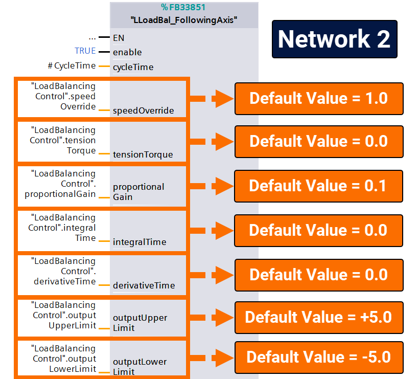
The function block for the following axis allows you to set controller parameters of load balancing using "ProportionalGain," "IntegralTime," and "DerivativeTime," and you can choose whether or not to utilize the derivative and integral aspects of the controller.
Furthermore, you can restrict the controller output (i.e., following axis additional speed setpoint) using the "outputLowerLimit" and "outputUpperLimit" input values. Initially, the limits are set at ±5 rpm and can be modified when configuring the load balancing controller (if needed).
Additionally, you can specify a fixed tension torque using the "TensionTorque" input, resulting in a consistent torque differential between the leading and following axes. Also, the tension torque is utilized to configure the load balancing controller.
You can adjust the following axis speed setpoint by utilizing the "SpeedOverride" in case you need it. By default, the override is set to 1.0, meaning that the following axis speed setpoint = 1.0 * leading axis speed setpoint.
When configuring the load balancing controller, the main idea is to fine-tune the proportional gain for fast regulation of deviations between the leading and following axes' torque setpoint values. Typically, a P-controller alone does the trick.
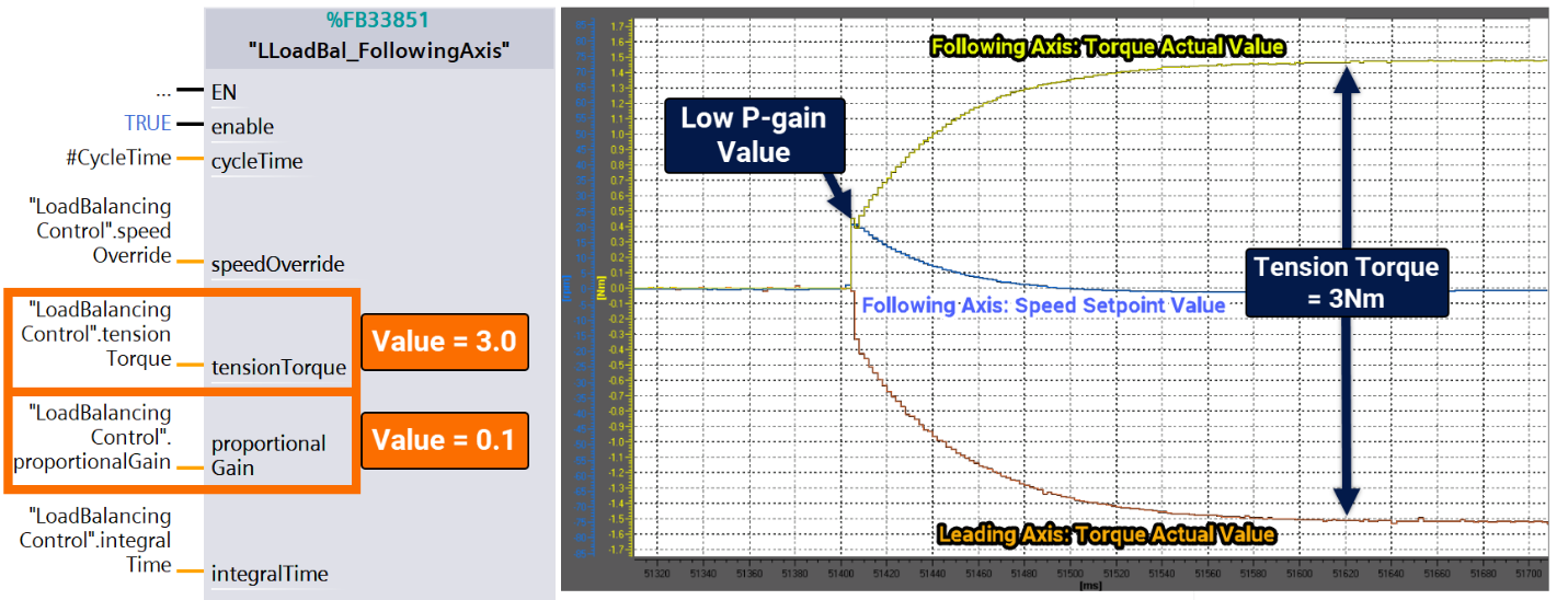
To kick things off, set a low proportional gain (0.1 or even lower) to assess the current situation. Continuously modify the value until you find a setting that works. To check the effectiveness of the adjustment, configure a SINAMICS trace that includes LeadingAxis.r80 (actual torque), FollowingAxis.r80 (actual torque), and FollowingAxis.r62 (speed setpoint).
When the leading and following axes are active, and if there are motor-holding brakes, you must introduce a sudden setpoint change in the load balancing controller. You can achieve this by utilizing the "tensionTorque" input in the function block of the following axis.
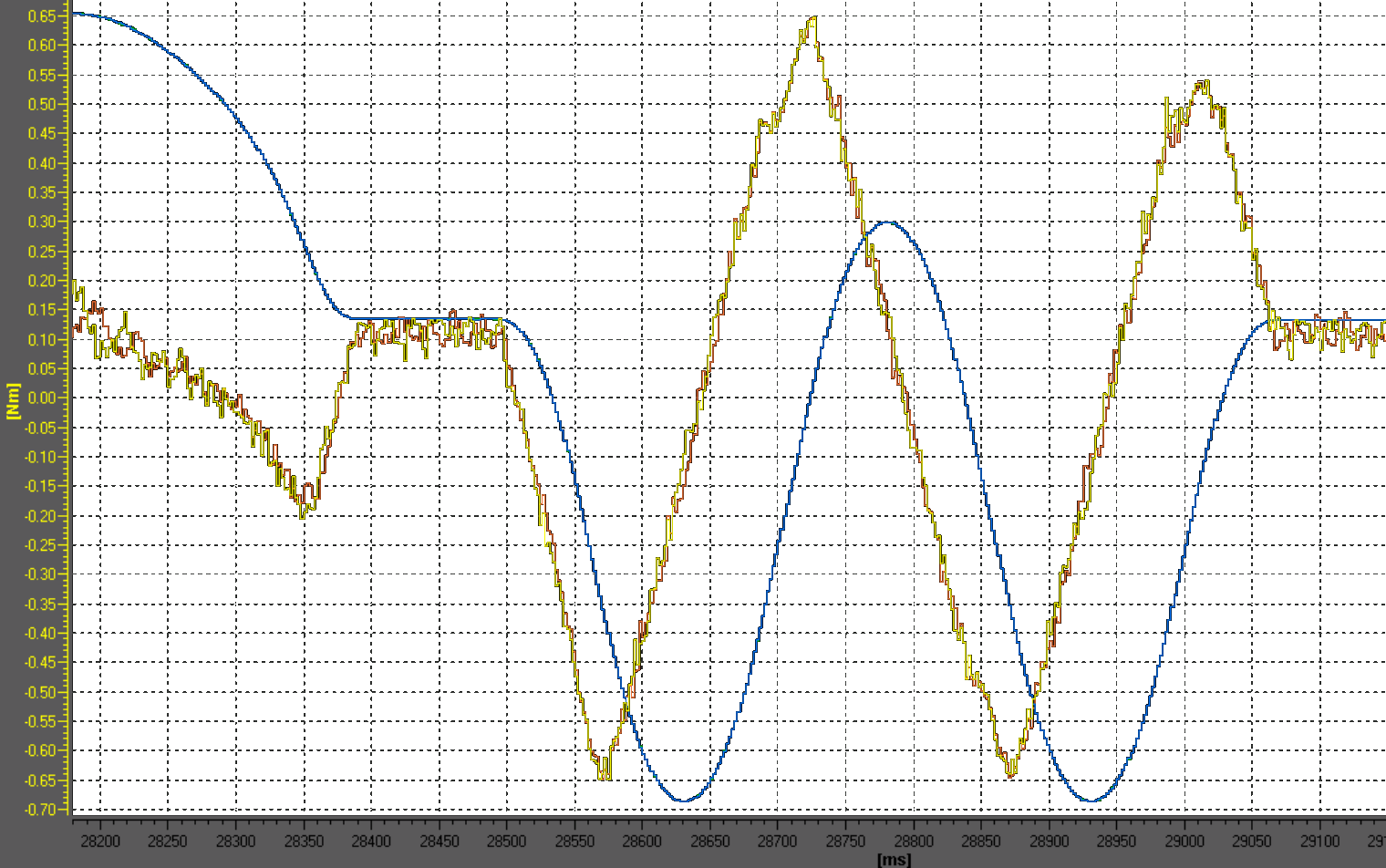
Check out the trace in Figure 4.5, and you'll see how the load balancing controller outputs a speed setpoint value (blue), resulting in a setpoint jump for the following axis. After about 250ms, the system achieves the specified tension torque of 3Nm, with the leading (orange) and following (yellow) axis actual torques having a symmetrical distribution of ± 1.5Nm. However, you can always ramp up the proportional gain for a quicker regulation time. The goal is to minimize the regulation time without surpassing the final value of the following axis's actual torque during the initial jump when reaching the applied tension torque.
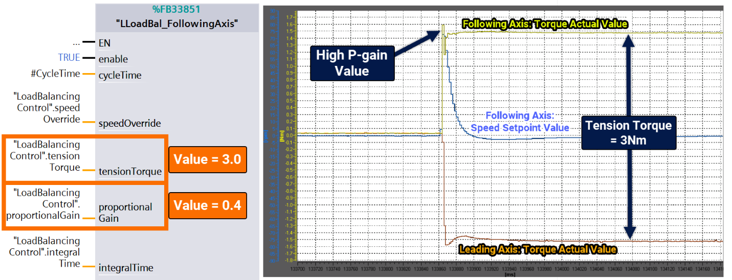
After that, we raise the proportional gain to 0.4. By applying a higher speed setpoint value (blue) to the following axis, the regulation time drops significantly, around 25ms. Even though the proportional gain is cranked up, the actual torque of the following axis (yellow) experiences an initial jump that surpasses the final value of 1.5Nm.
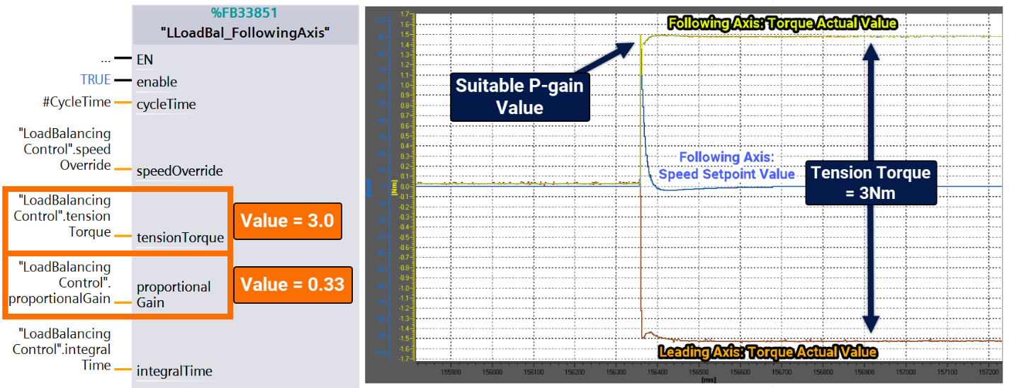
It's time to bring the proportional gain down just a notch. So, the next value comes to 0.33. The regulation time is still lightning-quick, around 50ms, and the jump of the actual torque of the following axis (yellow) doesn't surpass the final value. The proportional gain is nailing it.
Conclusion
In conclusion, you've learned the importance of load balancing when multiple motors operate together. Without proper load distribution, the motors can end up opposing each other and even start oscillating, leading to potential problems like overheating or tripping due to uneven loads or reaching maximum torque. It is necessary to have a robust mechanical connection between the motors to avoid these issues, ensuring the load is evenly distributed among all motors involved.
