Cookies are important for this site to function properly, to guarantee your safety, and to provide you with the best experience. By clicking OK, you accept all cookies. For more information, please access our Privacy Policy.
Table of Contents
Tutorials / 
Optimizing Torque Control of Siemens Servo Drives Through TIA Portal
Advanced

Optimizing Torque Control of Siemens Servo Drives Through TIA Portal

Siemens
TIA Portal
Hardware
Servo Motors

Introduction

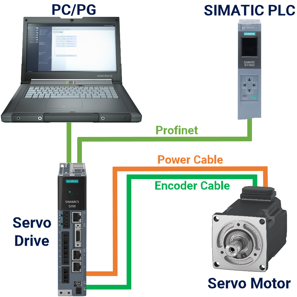
One of the cool features of the SINAMICS S200 PN servo drive system is called Telegram 750, which lets you fine-tune the torque settings like the extra torque, maximum and minimum limits, and the actual torque. This tutorial walks you through applying torque using SIMATIC S7-1500 PLC. Moreover, you can extend the content of this tutorial to torque applications with SIMATIC S7-1200 PLC as well. For a quick and clear understanding of the automation task, refer to Figure 1.1.

Figure 1.1: Applying torque to Siemens S200 servo drive - Automation task overview

Prerequisites

What you will need to follow along with this tutorial:

Fundamental Insights on Telegram 750

Table 2.1 presents all the details on supplementary Telegram 750. For this Telegram, the controller establishes communication by transmitting three words to the drive, and the servo drive sends back one word to the controller.

Table 2.1: Supplementary Telegram 750 overview

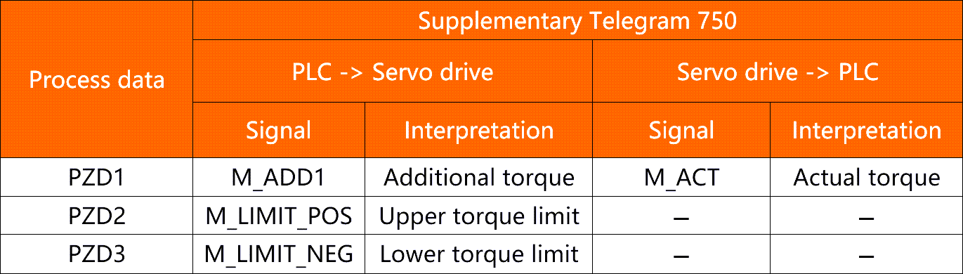
If you make any of the following settings while using Telegram 750, you better hold on tight because the motor unleashes its inner speed demon and accelerates like there is no stopping it:

  • Adjusting the upper torque limit to a negative value using the M_LIMIT_POS
  • Changing the lower torque limit to a positive value using the M_LIMIT_NEG

Applying Torque Using a Function Block

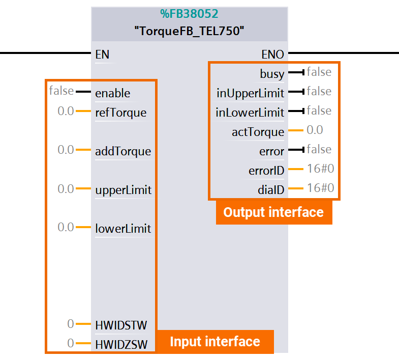
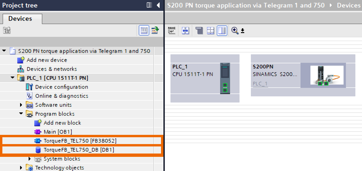
Check out Figure 3.1 for an in-depth view of the function block, specially crafted to utilize with SIMATIC S7-1500 and S7-1200 PLCs. Integrating FB38052 means you don't have to worry about creating the corresponding instance DB—it happens automatically. With this function block, you can cyclically take charge of a SINAMICS drive using the supplementary Telegram 750. The block's input interface includes seven inputs in various data formats. These inputs are preconfigured with initial values during the function block's initial configuration. Also, the block's output interface comes with seven outputs in various data formats.

Figure 3.1: Applying torque to Siemens S200 servo drive using function block - TorqueFB_TEL750 (FB38052)

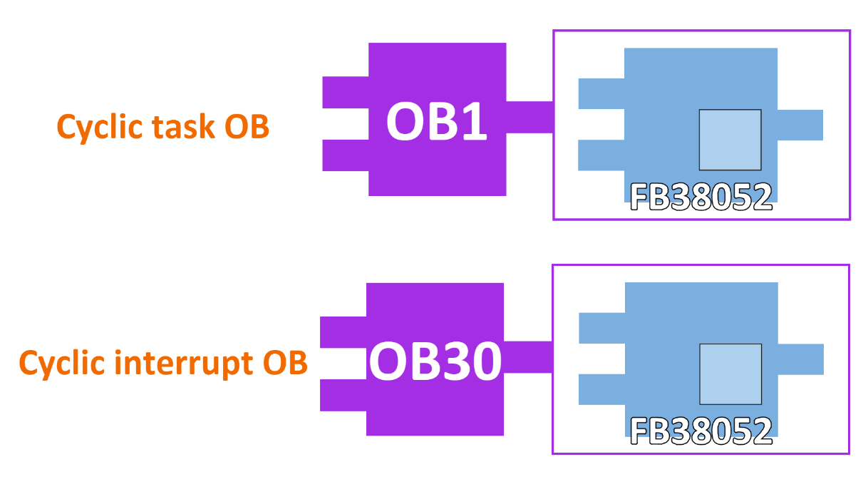
Here are the OBs where you can install the function block. OB1 is perfect for cyclic tasks or OB30 (or similar OBs) if you require cyclic interrupt tasks.

Figure 3.2: Applying torque to Siemens S200 servo drive using function block - Calling OBs

It is time to become pros at configuring and running the torque application with the help of Telegram 750 and Telegram 1. Start with a TIA portal project creation, then add the desired CPU and integrate the target servo drive (SINAMICS S200 PN) to the project using the GSDML file.

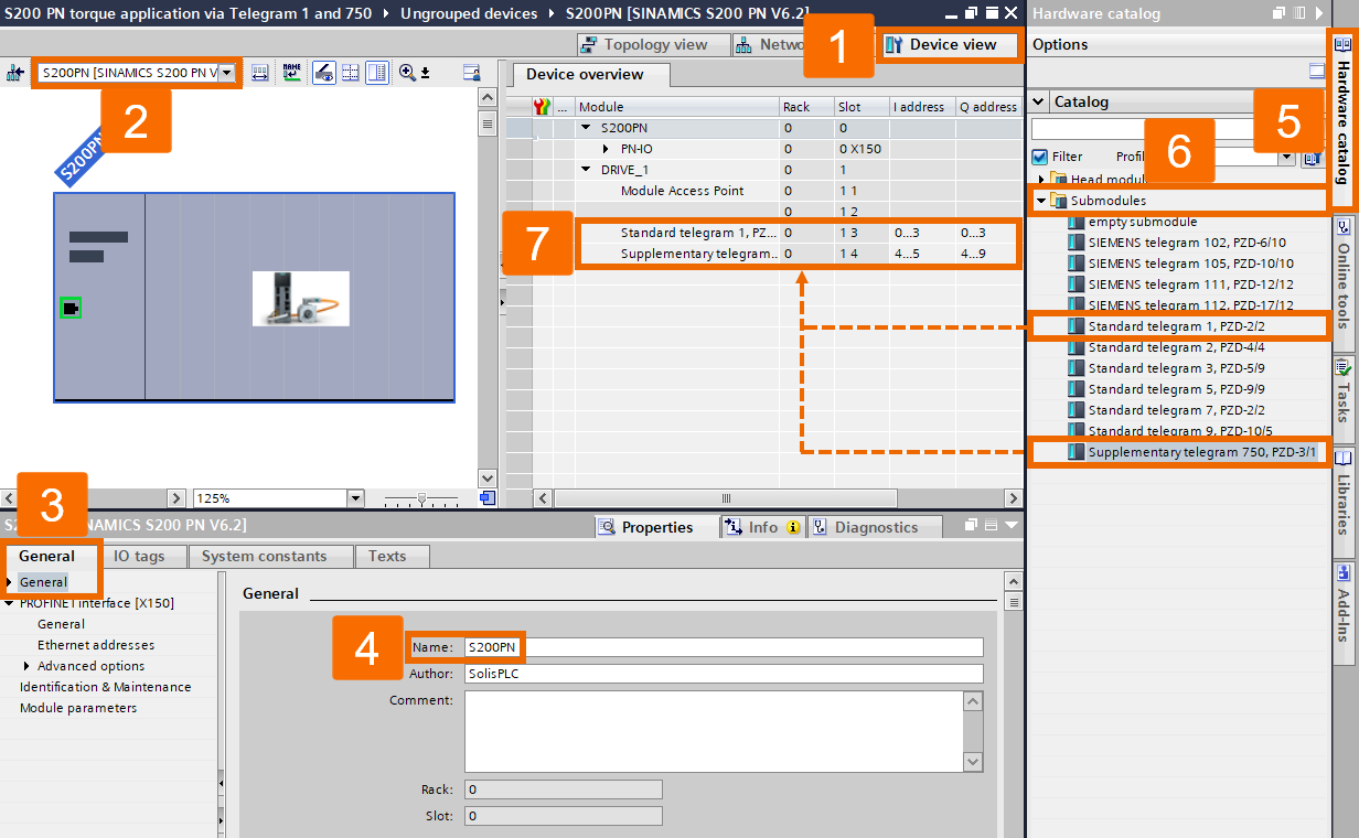
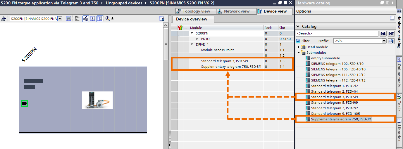
Then, transition to the Device View. Pinpoint the relevant SINAMICS S200 servo drive by selecting it from the options in the drop-down menu. Give the device a new name within the drive properties' general menu. Choose the Hardware Catalog tab. Expand the folder containing the submodules. Fit in the supplementary Telegram 750 alongside the standard Telegram 1 into your servo drive.

Figure 3.3: Applying torque to Siemens S200 servo drive using function block - Placing Telegram 750 and Telegram 1 into the drive

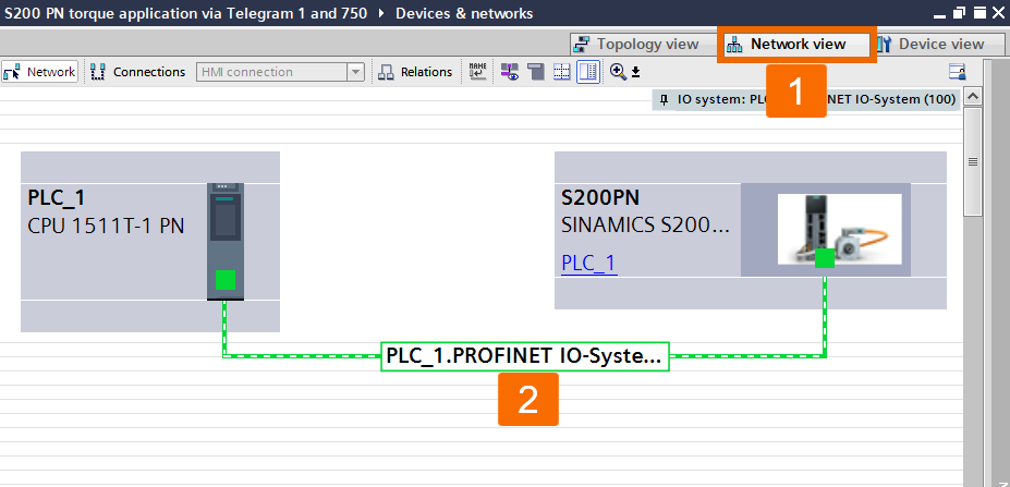
Hop over to the Network View and set up a Profinet connection between the PLC and the S200 servo drive.

Figure 3.4: Applying torque to Siemens S200 servo drive using function block - Setting up Profinet connection between PLC and Drive

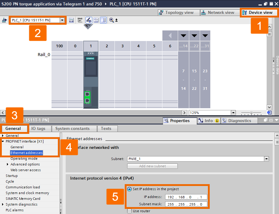
The CPU's IP address is 192.168.0.1.

Figure 3.5: Applying torque to Siemens S200 servo drive using function block - Configuring PLC’s IP address

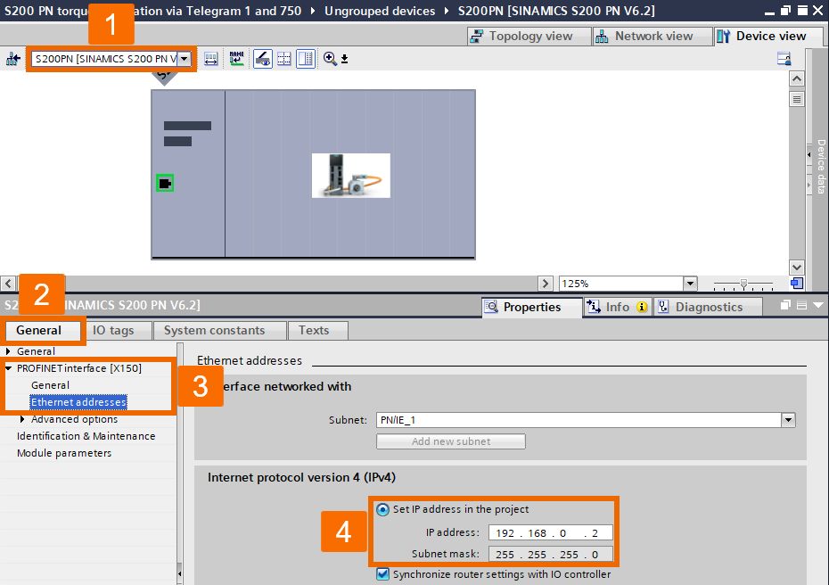
The S200 servo drive's IP address is 192.168.0.2. The Profinet connection is configured with a subnet mask of 255.255.255.0.

Figure 3.6: Applying torque to Siemens S200 servo drive using function block - Configuring Drive’s IP address

Contact the Siemens support in your area and request to download the TorqueFB_TEL750 library, and after that, include it in your project.

Figure 3.7: Applying torque to Siemens S200 servo drive using function block - Including TorqueFB_TEL750 library into the project

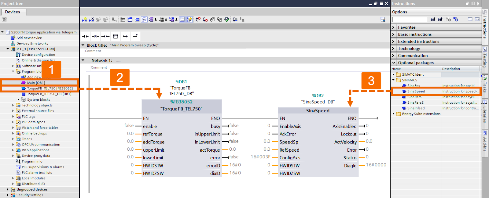
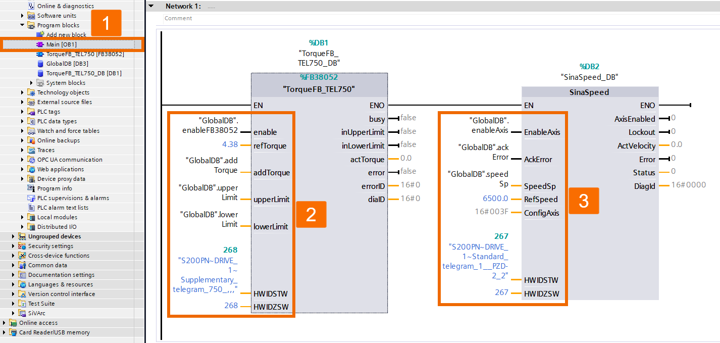
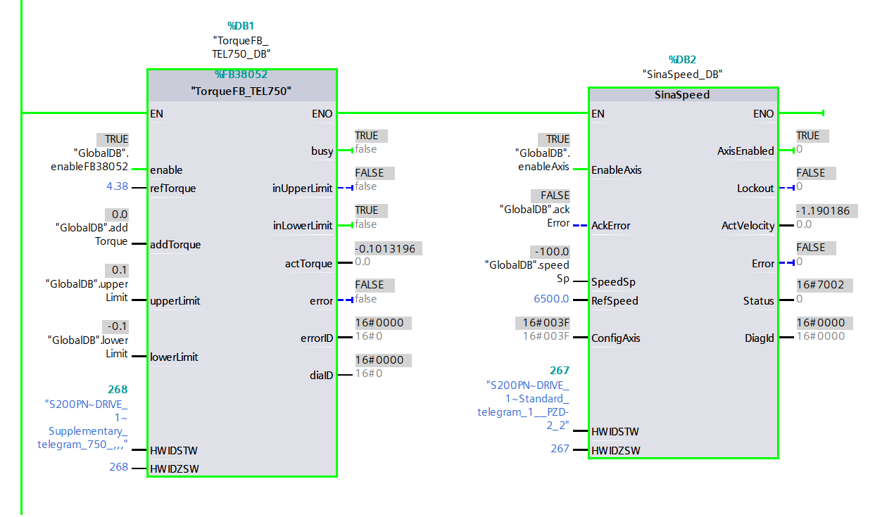
Access the Main [OB1] programming block and place SinaSpeed and FB38052 within Network 1.

Figure 3.8: Applying torque to Siemens S200 servo drive using function block - Creating network 1’s logic

Follow the lead from Figure 3.9 and Figure 3.10 and generate a global data block with the related variables.

Figure 3.9: Applying torque to Siemens S200 servo drive using function block - Creating global data block
Figure 3.10: Applying torque to Siemens S200 servo drive using function block - Generating related variables for the global data block

Tweak the PLC logic using those global variables you came up with.

Figure 3.11: Applying torque to Siemens S200 servo drive using function block - Configuring logic of network 1 via related variables of global data block

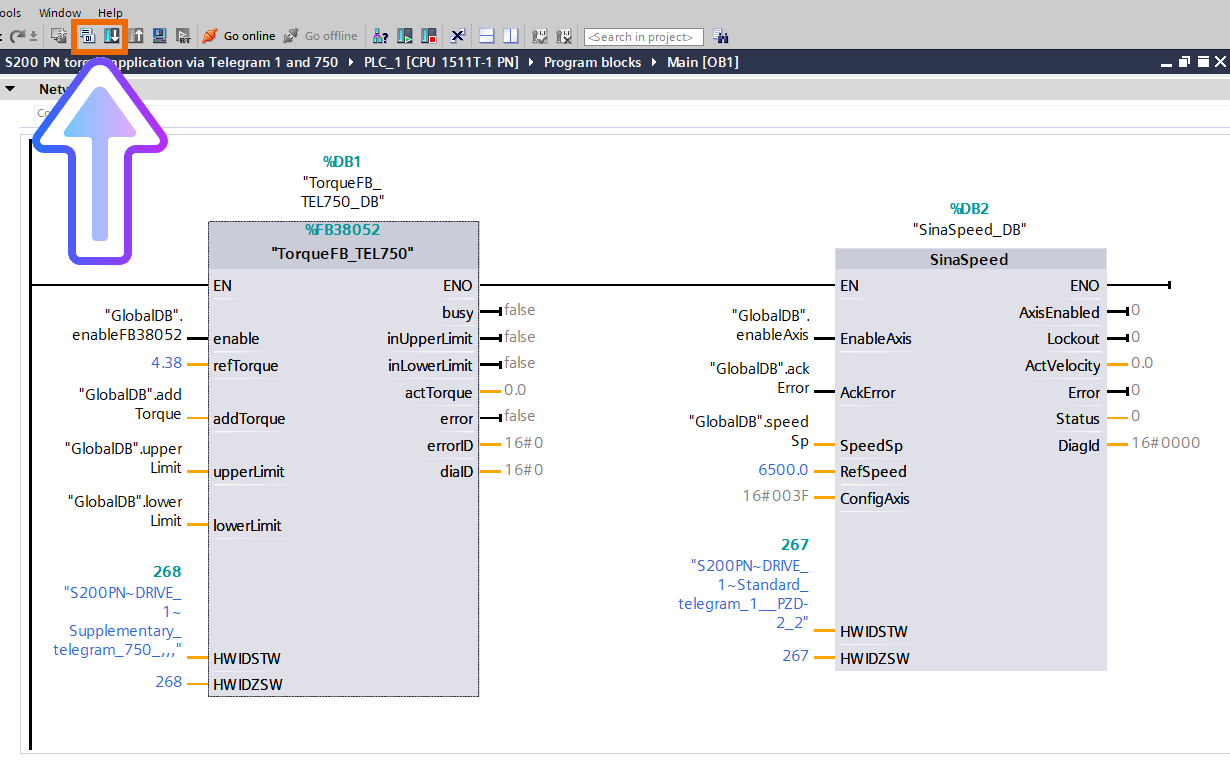
Make the project ready for compilation and then download it to the PLC.

Figure 3.12: Applying torque to Siemens S200 servo drive using function block - Compiling the project and downloading it to the PLC

Give the motor a spin and see if the load torque hits around 0.02Nm. Afterward, make sure the torque limit is set above the load torque.

Figure 3.13: Applying torque to Siemens S200 servo drive using function block - Giving the motor a spin

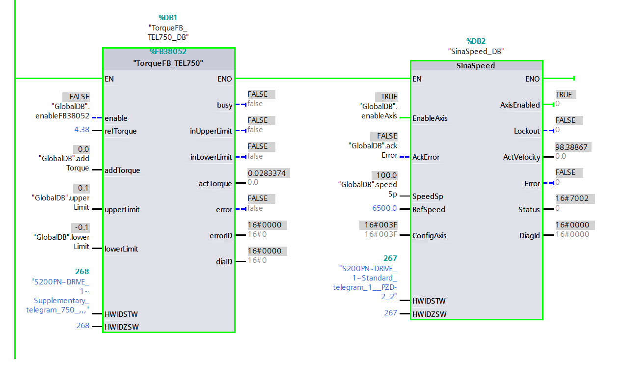
Activate the function block. Lock the motor in place, resulting in a velocity of 0, and cap the actual torque at the highest limit.

Figure 3.14: Applying torque to Siemens S200 servo drive using function block - Halting the motor

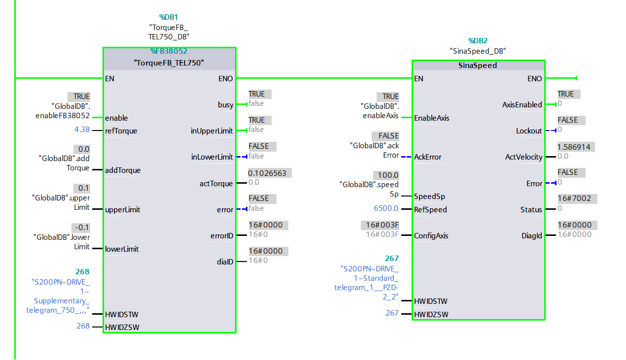
Alter the rotation direction, and then lock the motor. As a result, the velocity hits 0, and the torque is restricted to the minimum limit.

Figure 3.15: Applying torque to Siemens S200 servo drive using function block - Altering the motor rotation direction

Applying Torque Using the Technology Object in Real-Time

This section centers around the technology object that includes the speed axis, and its depiction is specifically outlined through Telegram 3 and the GSDML file. This part does not introduce any other telegram or technology object, including those in StartDrive. However, they can be referenced in this application. Now is the moment to uncover the specifics of configuring and operating the torque application using the supplementary Telegram 750 and the standard Telegram 3 via RT (real-time) communication.

Within this technique, after expanding the submodules folder, slap in the supplementary Telegram 750 and the standard Telegram 3 into your servo drive.

Figure 4.1: Applying torque to Siemens S200 servo drive using speed axis technology object - Placing Telegram 750 and Telegram 3 into the drive

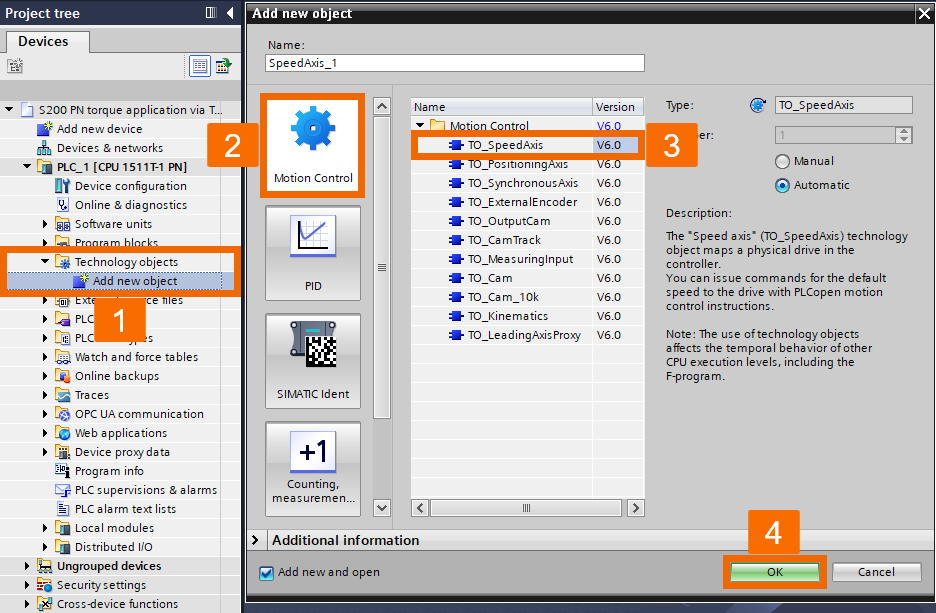
Once you establish the Profinet connection between the PLC and the servo drive, it is required to include the target technology object in the project. To do so, check out the project tree, expand the Technology objects folder, and double-click over the Add new object to open it up. Under Motion control, you want to select the TO_SpeedAxis, hit OK, and watch this speed axis tech object become part of your project.

Figure 4.2: Applying torque to Siemens S200 servo drive using speed axis technology object - Creating speed axis technology object

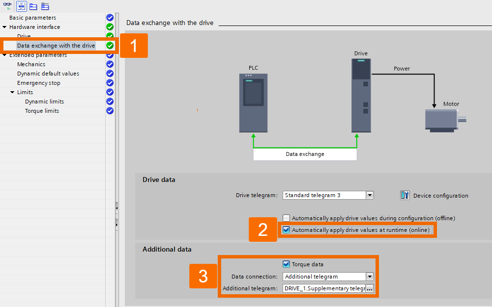
Within the Function view, select the Drive menu. Pop open that screen by hitting the button. Pick the telegram you are aiming for. Hit OK to toss this data into the properties of the drive.

Figure 4.3: Applying torque to Siemens S200 servo drive using speed axis technology object - Configuring drive menu setting

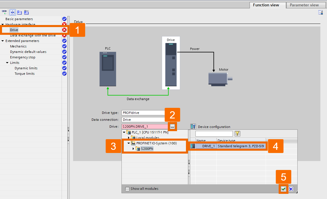
Check the checkbox for the feature that applies drive values automatically while the system is running (online). Once you've appropriately configured Telegram 750, the torque data kicks in automatically, and by default, the Data connection and additional Telegram properties are set up automatically.

Figure 4.4: Applying torque to Siemens S200 servo drive using speed axis technology object - Configuring data exchange with the drive

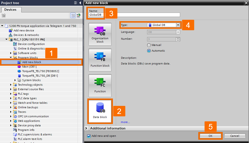
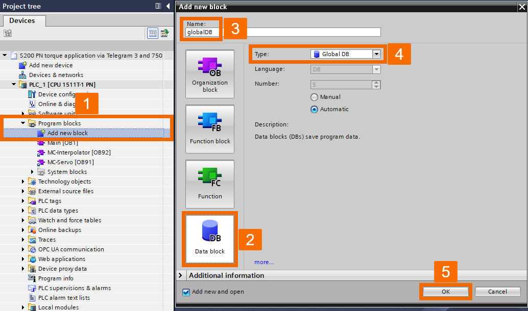
Under the PLC_1 item in the project tree, expand the Program blocks folder and double-click over the Add new block to generate a global data block called globalDB.

Figure 4.5: Applying torque to Siemens S200 servo drive using speed axis technology object - Creating global data block

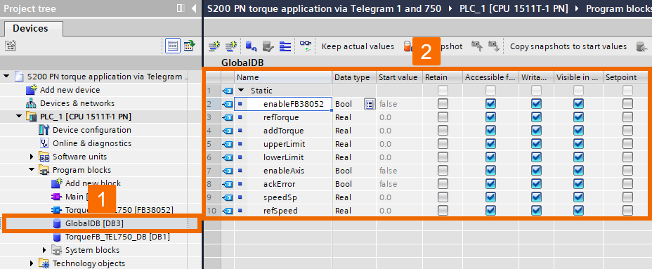
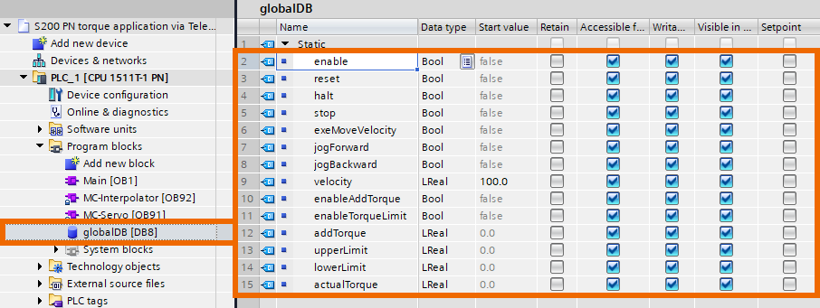
When the global data block window opens, tweak the corresponding table with related variables, as shown in Figure 4.6.

Figure 4.6: Applying torque to Siemens S200 servo drive using speed axis technology object - Generating related variables of global data block

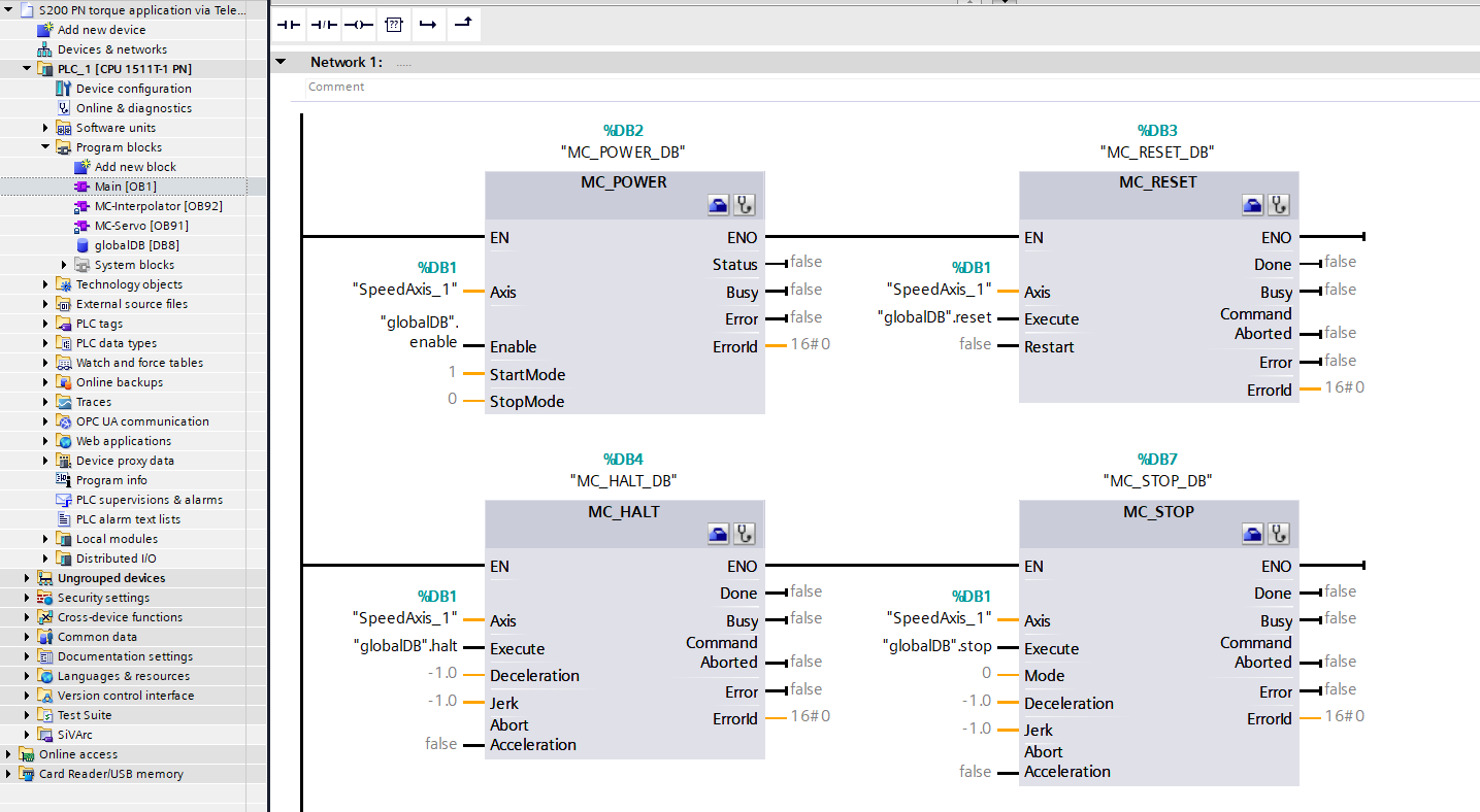
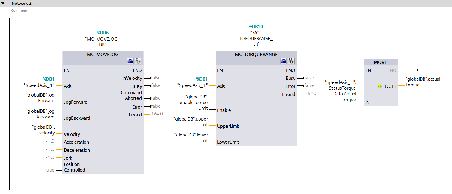
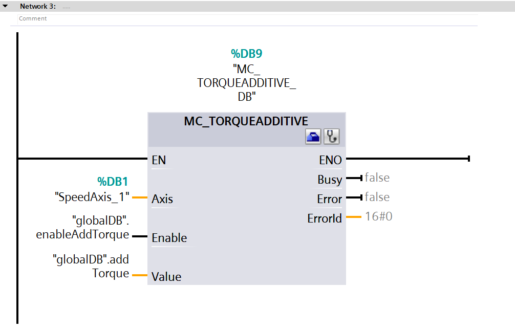
Open up the main organization block (Main [OB1]) and create some logic in network 1, network 2, and network 3, as depicted in Figures 4.7, 4.8, and 4.9. Ensure that you compile the project and then initiate the download to the PLC.

Figure 4.7: Applying torque to Siemens S200 servo drive using speed axis technology object - Creating logic of network 1
Figure 4.8: Applying torque to Siemens S200 servo drive using speed axis technology object - Creating logic of network 2
Figure 4.9: Applying torque to Siemens S200 servo drive using speed axis technology object - Creating logic of network 3

Give the motor a spin and ensure the load torque is at 0.02Nm. Afterward, adjust the torque limit to a value higher than the load torque and activate the block that limits torque.

Figure 4.10: Applying torque to Siemens S200 servo drive using speed axis technology object - Giving the motor a spin

Halt the motor (prevent the motor from moving), restricting the actual torque to the lower limit value.

Figure 4.11: Applying torque to Siemens S200 servo drive using speed axis technology object - Halting the motor

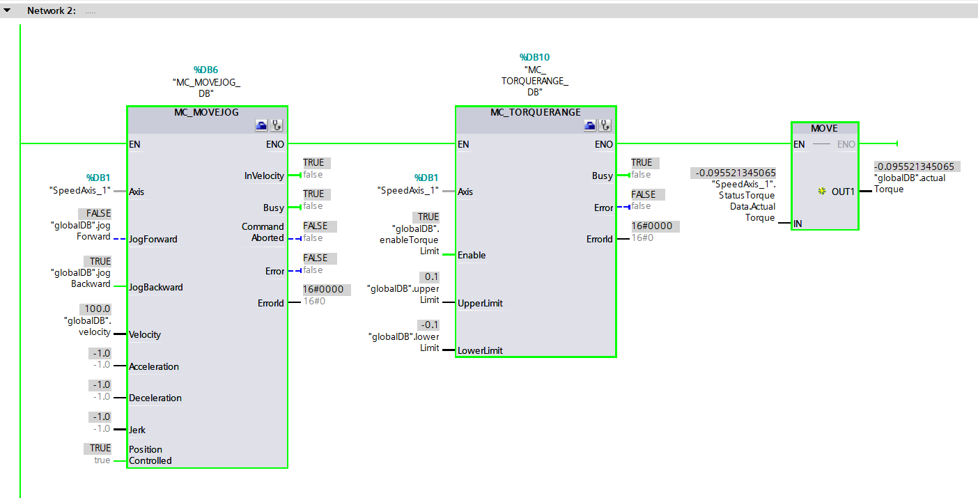
Switch the direction of rotation and once more halt the motor; the actual torque is restricted to the uppermost value.

Figure 4.12: Applying torque to Siemens S200 servo drive using speed axis technology object - Altering the motor rotation direction

Applying Torque Using the Technology Object in Isochronous Real-Time

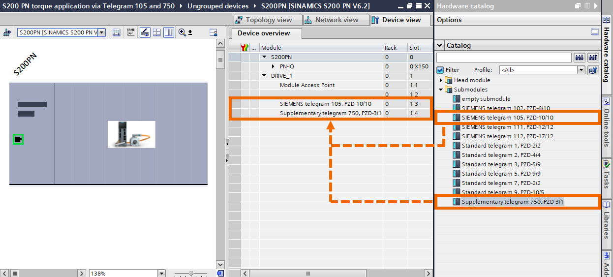
This section centers around the technology object that includes the position axis, and its depiction is specifically outlined through Telegram 105 and the GSDML file. Now is the moment to uncover the specifics of configuring and operating the torque application using the supplementary Telegram 750 and the standard Telegram 105 via IRT (isochronous real-time) communication. Within this technique, after expanding the submodules folder, slap in the supplementary Telegram 750 and the standard Telegram 105 into your servo drive.

Figure 5.1: Applying torque to Siemens S200 servo drive using position axis technology object - Placing Telegram 750 and Telegram 105 into the drive

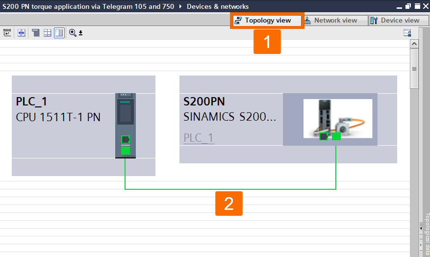
Shift to the Topology view and customize the topology using the actual connection.

Figure 5.2: Applying torque to Siemens S200 servo drive using position axis technology object - Using the actual connection to configure the topology

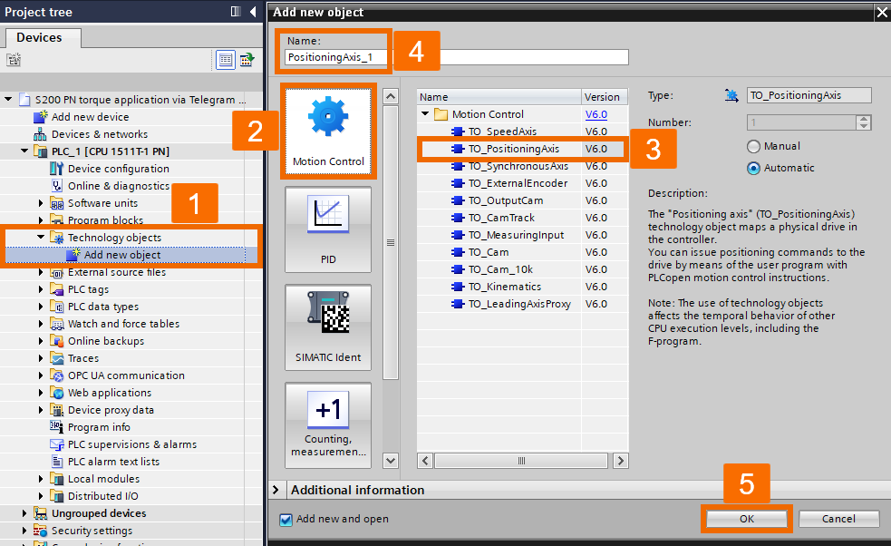
Expand the Technology objects folder within the project tree on the left pane, and double-click over the Add new object to open it up. Under Motion control, you want to select the TO_PositioningAxis, hit OK, and watch this position axis tech object become part of your project.

Figure 5.3: Applying torque to Siemens S200 servo drive using position axis technology object - Creating position axis technology object

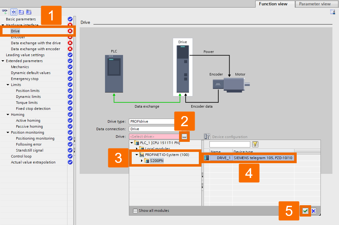
Arrange the Drive menu to incorporate Siemens Telegram 105.

Figure 5.4: Applying torque to Siemens S200 servo drive using position axis technology object - Configuring drive menu setting

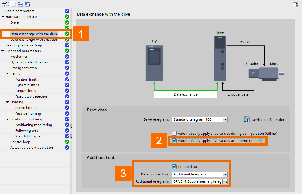
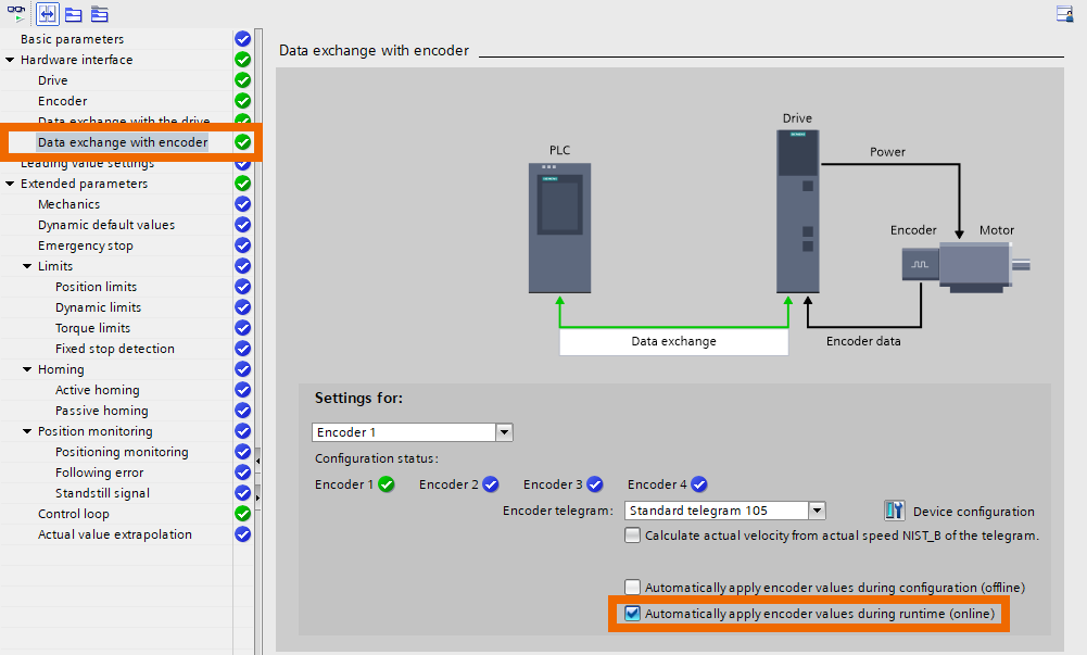
When configuring the setting of the Data exchange with the drive function, enable the feature that applies drive values automatically while the system is running (online) to retrieve the drive data automatically. When Telegram 750 is appropriately configured in the servo drive, the additional data will be automatically updated with the torque details.

Figure 5.5: Applying torque to Siemens S200 servo drive using position axis technology object - Configuring data exchange with the drive

Within the Data exchange with encoder menu, check the checkbox for the option that automatically applies encoder values while it's running (online).

Figure 5.6: Applying torque to Siemens S200 servo drive using position axis technology object - Configuring data exchange with encoder

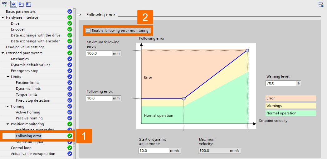
Toggle off the error monitoring function so you don't have to deal with the annoying error alarm while using torque limit functions for positioning. Alternatively, set up an appropriate value for testing the torque limit functions.

Figure 5.7: Applying torque to Siemens S200 servo drive using position axis technology object - Disabling error monitoring function

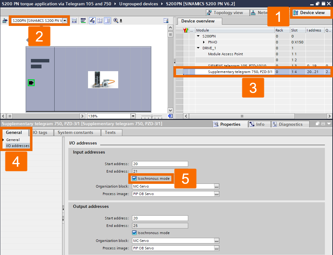
Switch to the Device view. Make a selection of the S200 servo drive. Pick out the supplementary Telegram 750. Then, navigate to the Properties in the inspector window to enable the isochronous mode.

Figure 5.8: Applying torque to Siemens S200 servo drive using position axis technology object - Enabling isochronous mode for Telegram 750

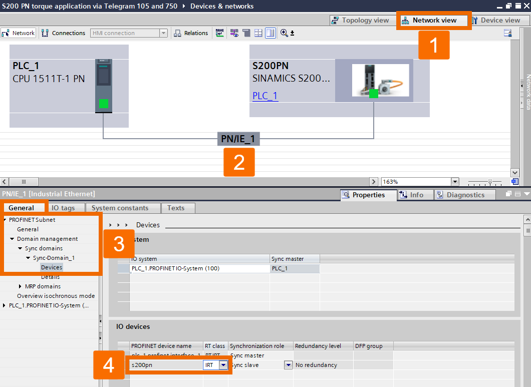
Hop to the Network view and single out PN/IE_1. Under the General tab, navigate Domain management -> Sync domains -> Sync-Domain_1 to reach the Devices item. From there, tweak the properties to switch the RT class to IRT communication.

Figure 5.9: Applying torque to Siemens S200 servo drive using position axis technology object - Configuring IRT communication for S200 servo drive

Under the Program blocks folder, generate a global data block and tweak the corresponding table with related variables, as shown in Figure 5.10.

Figure 5.10: Applying torque to Siemens S200 servo drive using position axis technology object - Creating related variables for the global data block

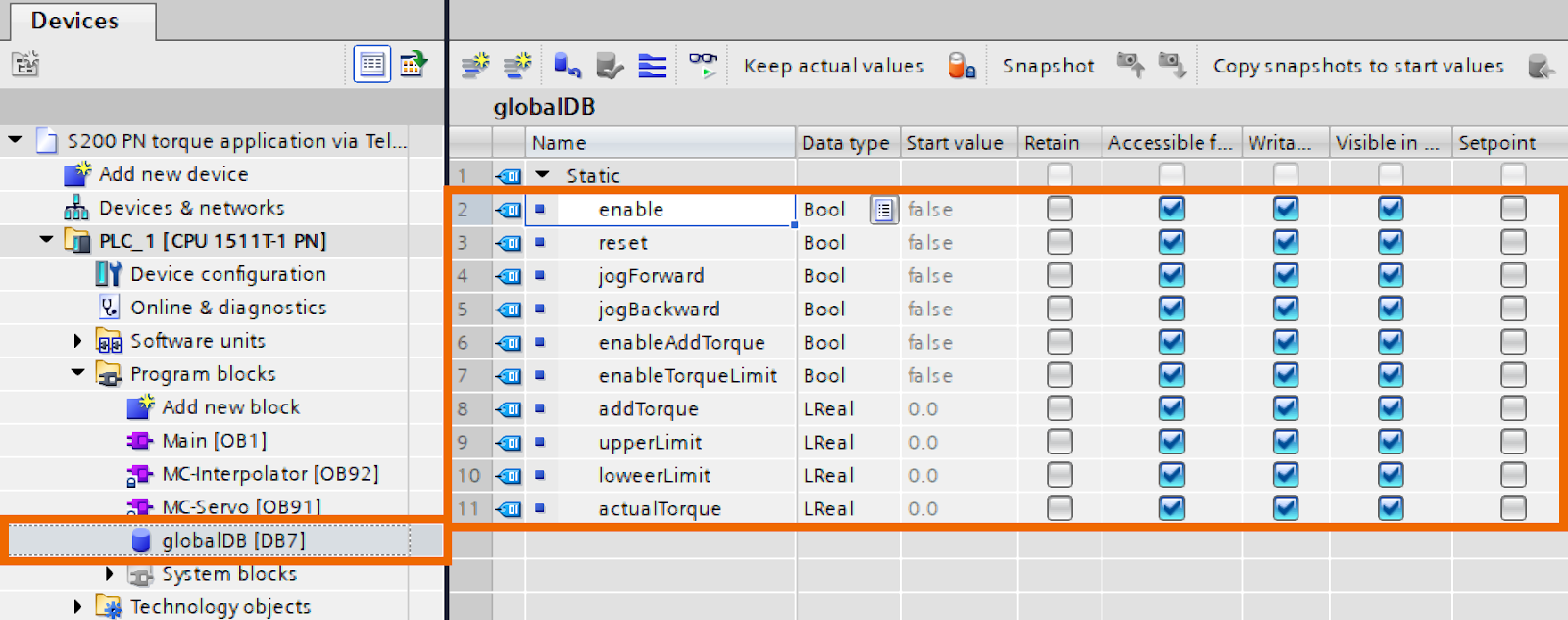
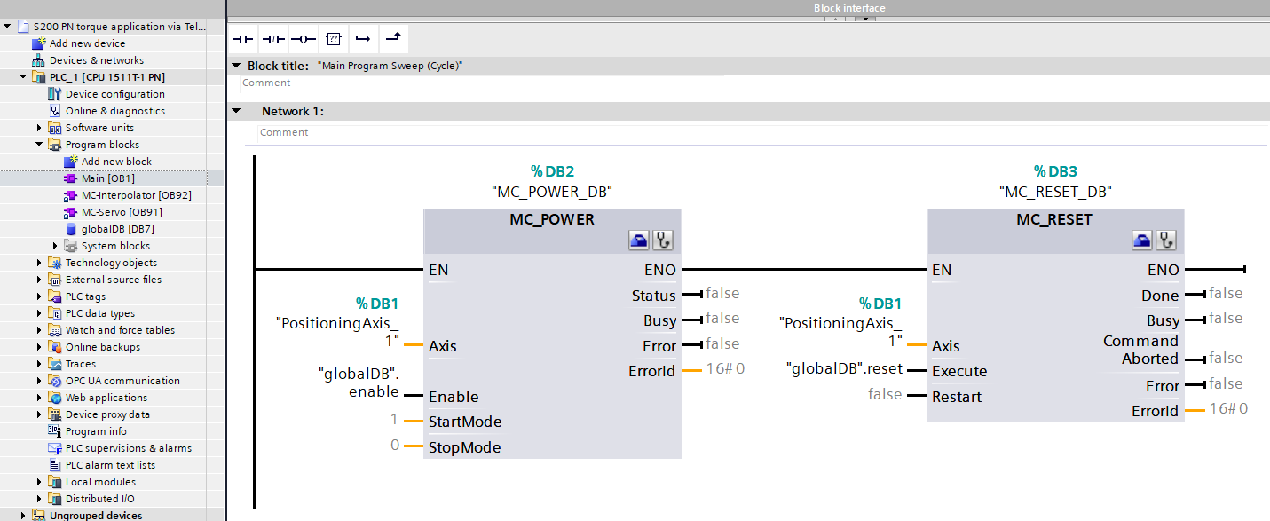
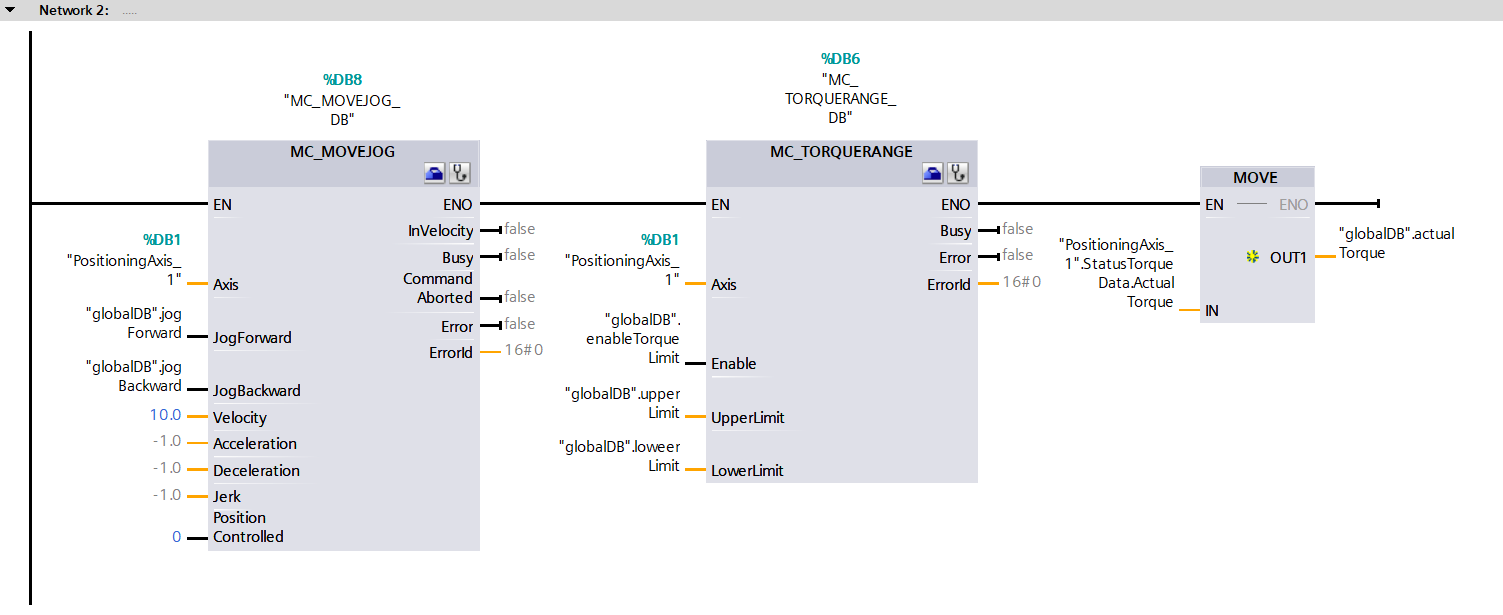
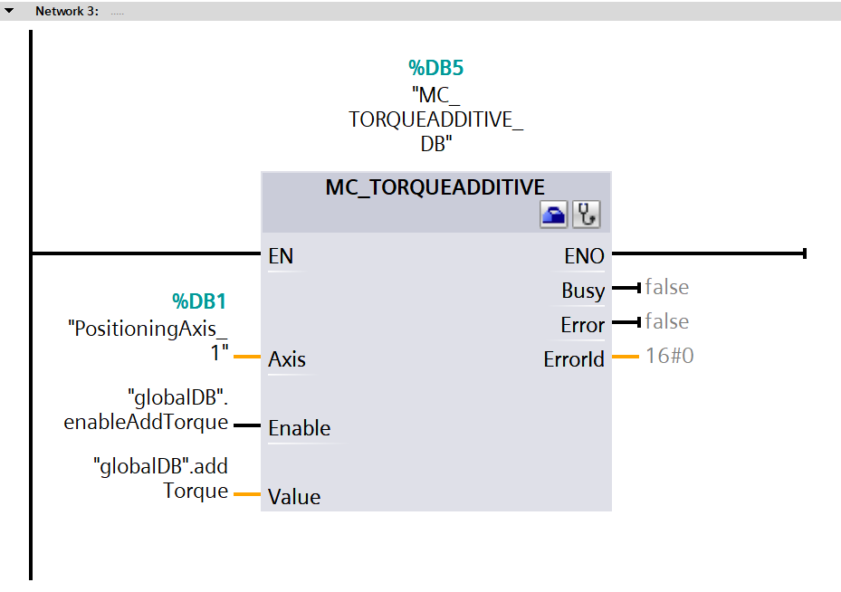
Open up the main organization block and create some logic in network 1, network 2, and network 3, as depicted in Figures 5.11, 5.12, and 5.13. Ensure that you compile the project and then initiate the download to the PLC.

Figure 5.11: Applying torque to Siemens S200 servo drive using position axis technology object - Creating logic of network 1
Figure 5.12: Applying torque to Siemens S200 servo drive using position axis technology object - Creating logic of network 2
Figure 5.13: Applying torque to Siemens S200 servo drive using position axis technology object - Creating logic of network 3

Give the motor a spin and ensure the load torque is at 0.02Nm.

Figure 5.14: Applying torque to Siemens S200 servo drive using position axis technology object - Giving the motor a spin

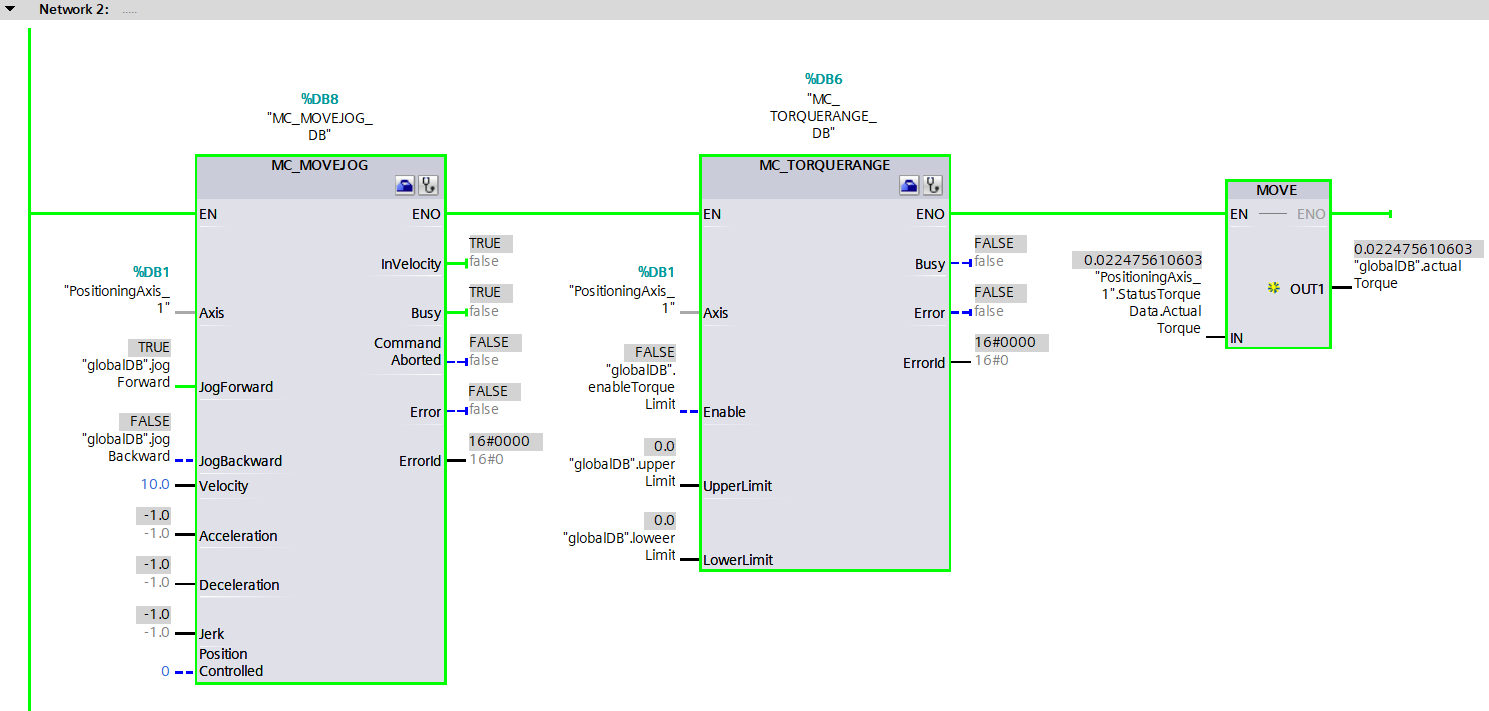
Bump up the torque limit above the load torque and activate the torque limit function. Bring the motor to a halt and verify that the actual speed registers as 0 while ensuring that the actual torque is restricted to the upper limit value.

Figure 5.15: Applying torque to Siemens S200 servo drive using position axis technology object - Halting the motor

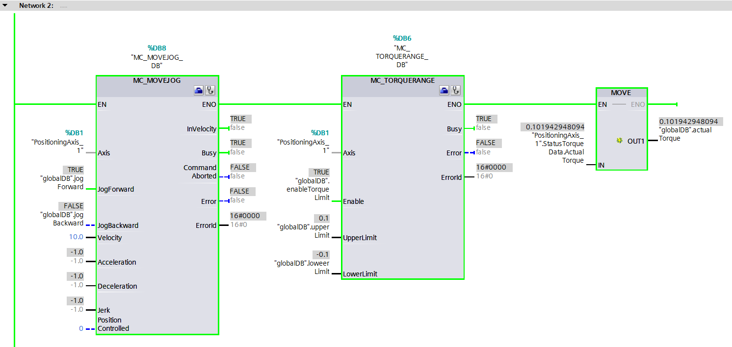
Switch the direction of rotation and once more halt the motor. Verify that the actual speed is at 0 and the actual torque is restricted to the lowermost value.

Figure 5.16: Applying torque to Siemens S200 servo drive using position axis technology object - Altering the motor rotation direction

Conclusion

In conclusion, you learned about fundamental insights on Telegram 750, and you understood by integrating FB38052, you can cyclically take charge of the S200 servo drive. Finally, you figured out how to apply torque to the Siemens S200 servo drive using technology objects - speed and position - in real-time and isochronous real-time.