Data Structures and UDT in RSLogix 5000 PLC Programming

Data Structures in PLC Programming
A key concept in PLC programming is data structures. They govern how data is captured by the inputs, processed by the PLC and is sent out to the outputs and field devices. A skilled PLC programmer is comfortable working with all of the data structures we will cover in this post. In addition to the base constructs, vendors (Allen Bradley, Siemens, Opto 22, and others) have created vendor defined data types that can be used in special applications. Examples include timers, counters, motion, and more. Lastly, we’ll dive into User-Defined Data Types, or UDTs; a way for the PLC programmer to create their own definition of a data structure. We’ll answer the why, how and when to use UDTs.
Basic Data Structures
In this section, we’ll cover the basic data structures from an RSLogix 500 standpoint. In each section, we’ll contrast some of the features of RSLogix 500 to RSLogix and Studio 5000 that every PLC programmer should be aware of.
Binary or Boolean (BOOL) Data Type
A binary value can take on two values: 0 or 1.
Binary values are used for digital input states. Examples of such devices include a proximity sensor, a gate switch, a relay state, a contactor state and more.
Creating an array of Binary Tags in RSLogix 500
Step 1 - Right click “Data Files” and select “New…”
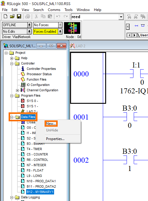
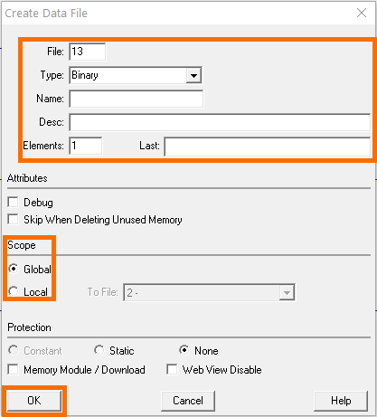
Step 2 - Specify “Type”, “Name”, “Elements” and “Scope”
The “File” field should default to the next “unused” location on the PLC.
The “Type” field should be set to “Binary”.
The “Name” field is required.
The “Desc” field is optional.
The “Elements” field specifies the number of Binary arrays to create.
Exploring Binary Tags in RSLogix 500
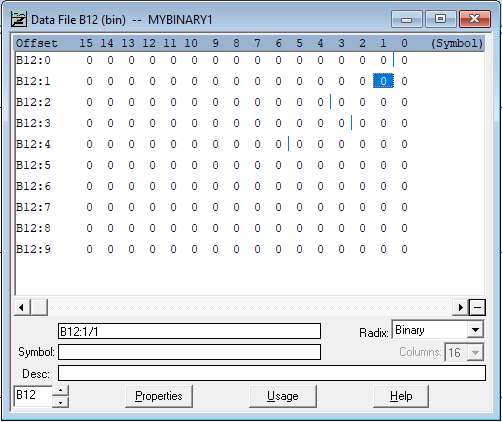
Once the array is initialized, the user can open the file and inspect the state of the bits within.
In RSLogix 500, the “Elements” field specified above will dictate the number of integer (16 bit) arrays created.
In addition to the state of the bits, the “Data File” allows the PLC programmer to add a Description for each bit. Note that specifying a description in this field is different from the “Desc” above. In this instance, you will be prompted to specify a description on a single bit basis.
Using Binary Tags in RSLogix 500
Binary tags are used in a wide range of instructions. Most commonly in XIC (Examine if Closed), XIO (Examine if Open) and OTE (Output Energize).
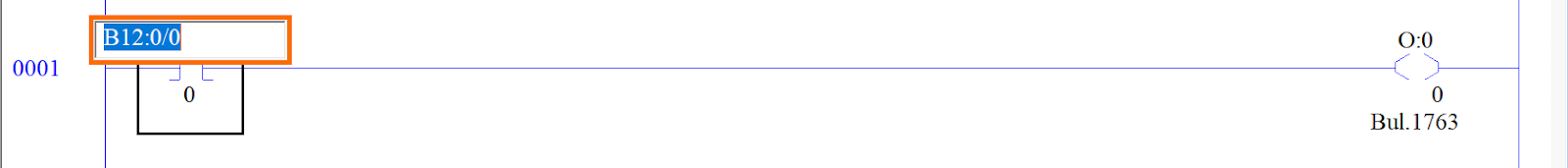
In order to address a binary address, you’ll need to specify the array and the bit address.
- Example: in the “Data File B12” above, you may choose to use the first bit by calling the address “B12:0/0”
Creating a Boolean Tag in RSLogix 5000 / Studio 5000
The name of a binary tag in RSLogix 5000 and Studio 5000 is “Boolean” or “BOOL”. Furthermore, tags are created on an individual basis. In other words, it’s possible to create a single bit tag.
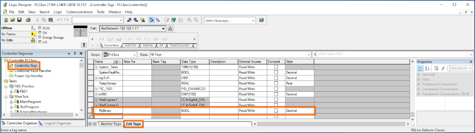
Step 1 - Open “Controller Tags” or “Program Tags”
Step 2 - Open the “Edit Tags” tab
Step 3 - Create a new tag by specifying the “Name” and “Data Type”
Set “Data Type” to BOOL.
Using Binary Tags in RSLogix 5000 and Studio 5000
In the recent installments of RSLogix, the use of Booleans is slightly different than in RSLogix 500. In RSLogix 5000 and Studio 5000, the BOOL tags can be used directly without specifying the address of the register.
Integer Data Type
An integer contains 16 bits (or Booleans). Integers are used to store limits, setpoints, sensor values, etc.
The 16-bit nature of an Integer implies a finite range. In most cases, 15 bits are used for the value, while the last bit represents the sign (+ or -). In a practical sense, it’s good to know that a 16 bit integer can hold a value from -32768 to 32767. If the integer
Overflow - A fault that occurs when an integer is increased or decreased below the boundaries specified above.
It’s important to note that an Overflow will cause unexpected behaviour if it isn’t handled properly. In RSLogix 500, by default, an Overflow will cause the system to shut down and require a manual reset. In RSLogix 5000, a minor fault is thrown; the number will cycle back to 0.
Exploring Integer Tags in RSLogix 500
To create a new Integer file, follow the same steps as above, but specify the “Type” to be Integer.
Once created, we can see the array, based on the number of elements, appear under “Data Files”. Integers are specified by the “N” prefix and will display the same way as the binary elements we looked at earlier.
“Under the Hood”, the programmer may view the state of each bit of an integer. Furthermore, they may choose to use an element of an Integer in an instruction that would require a binary or boolean tag.
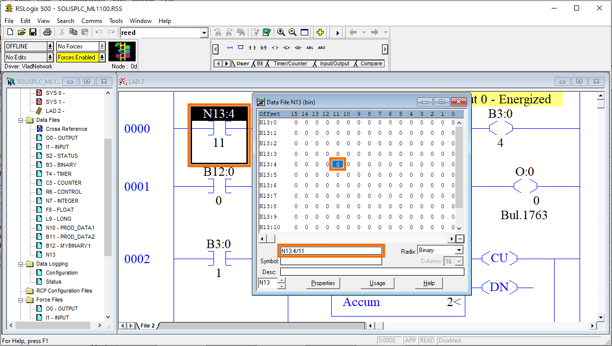
Note that the example above illustrates the use of the 11th bit of Integer 4 within file 13 in the context of an XIC instruction. The same can be accomplished in RSLogix and Studio 5000 PLC Programming.
In RSLogix 500, the user may choose to view the integer in Binary or Decimal form. This is important as in many cases, the programmer may need to view either case.
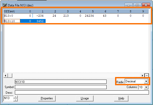
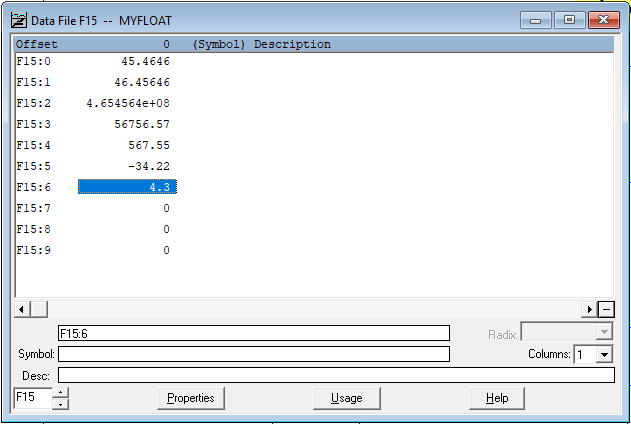
In the view above, when “Radix” of Decimal is selected, the programmer will be shown the values of each Integer in Decimal form.
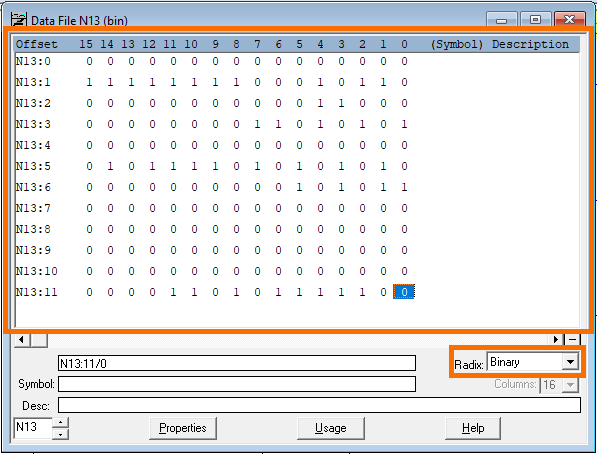
The view above displays the exact same integers in Binary form. Here, the user will get an address for each bit of the integer and is able to utilize them in bit based commands as demonstrated previously.
Float or REAL Data Type
A Float data type is used for analog data. The data will contain a value for the integer and decimal as part of the float.
Note: you may use an Integer in certain cases of analog data where precision is not an issue. In other words, you may store the value of an analog sensor within an integer. However, an integer does not provide the decimal. (Ex: 100.45 Float -> 100 Int)
Exploring Float Tags in RSLogix 500
To create a Float in RSLogix 500, you’ll follow the steps outlined above. In the “Type” field, choose “Float” and press on “Create”.
It’s important to note that you may utilize a Float instead of an integer in certain cases. However, data loss may occur when certain operations are performed. We always recommend that you stick to the data and registers of the same type unless you absolutely must convert from one to the other. It’s also advised to use integers over floats when possible. For example, you may need to create a software limit for an analog signal. The limit may be created as an integer.
Intermediate Data Structures
Now that we’ve covered the three basic structures, boolean, integer and float, we can move onto intermediate ones. We won’t cover every possible variation of every register, but rather focus on what a programmer should absolutely be familiar with. We encourage you to explore the diverse pre-defined tags on your own.
Instruction Specific Data Types
Instruction specific data types are used to capture key data and facilitate development. The most basic examples are the Counter and Timer data types. In RSLogix 500, RSLogix 5000 and Studio 5000, the PLC programmer is required to initialize these data types in order to use the instructions mentioned above.
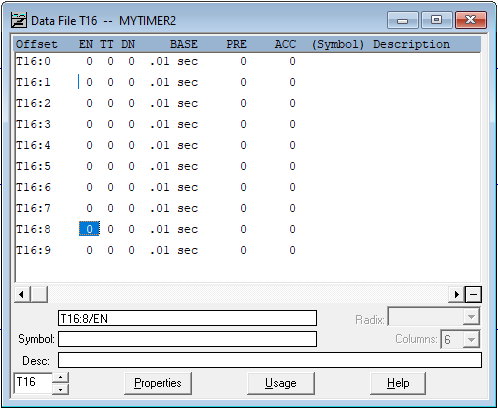
As a 10x timer data structure is created in RSLogix 500, we can see the view above. Here you'll notice that a timer contains multiple basic structures within one. The EN, TT and DN data is binary; they can be 0 or 1. The BASE structure is a selector; a dropdown. The PRE and ACC structures are integers. These integers store the value of when the timer is set and what is the current value of the timer increment.
What’s important to note is that the Timer construct can be used in multiple ways in PLC programming. The most obvious way is the TON or TOF instructions. In these instances, the timer construct must be utilized. However, the PLC programmer has access to the EN, TT, DN, PRE and ACC registers in their respective capacities. The user can utilize any other instruction that would fit the specific data types. Ex: XIC and XIO for the DN bits to check if the timer is completed.
Studio 5000 Timer and Counter Data Structures
In RSLogix and Studio 5000, the timer construct contains the same elements as the ones in RSLogix 500.
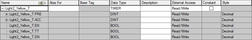
The timer above indicates the same breakdown of the data structure into sub elements: DN, TT, EN, ACC and PRE basic structures are available for the user. It’s important to note that we haven’t covered the DINT structure that is used for the PRE and ACC registers. The DINT is a Double Integer register that contains double (32) the bits of an Integer.
The counters have a similar structure with different data types. Here’s a screenshot from Studio 5000.
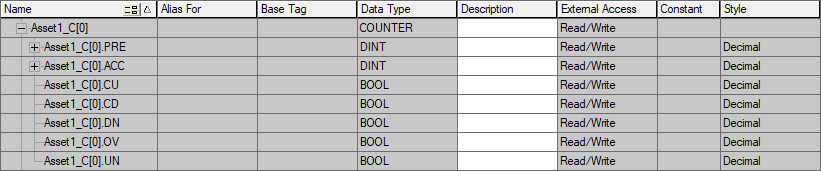
It’s important to note that the tags are not the same as they were for the Timer. However, the structure is still broken down into DINTs and BOOLs.
Vendor Specific Data Structures
RSLogix and Studio 5000 have an extensive library of “Predefined” data types that have been supplied by the vendor. The Timer and Counter structures fall within this category. The definition of all other data types is found under the definition within the IO tree shown below.
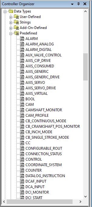
The data structures above are specific to the use cases they serve. As shown, a number of data types are prefixed with “AXIS”. These data types are used in servo motion controls.
Advanced Data Structures - User Defined Data Types
The examples above have all been pre-created for the user. It’s possible to create an instance of any of the structures above by creating a new set of tags in RSLogix 500 or RSLogix 5000. However, RSLogix 5000 and Studio 5000 have introduced the possibility of adding user defined data types or UDTs. They are nothing more than a custom set of data as the ones discussed above.
Why are UDTs useful?
The traditional approach of creating a set of tags is through arrays of data. In other words, the PLC programmer may allocate an array of BOOLs, DINTs, Timers and other tags for the application. When such an approach is utilized, there is no cohesion between the tags within an array. It’s possible to allocate tags on a device basis, but this approach does not scale. Let’s look at an example.
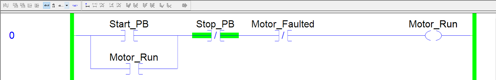
In the simple example above, a programmer has created a rung of logic that has 4 distinct BOOL tags. As he decides to create a second motor starter rung, he’ll have to create a new rung, 4 new tags and most likely label them as “Start_PB2”, “Stop_PB2”, etc. It’s apparent that approaching development in such a manner is tedious. Furthermore, it becomes confusing to troubleshoot and allocate proper resources outside of the PLC to this data.
A way around the individual tag limitations, as mentioned above, is to pre-allocate arrays. Here’s an example of this practice.
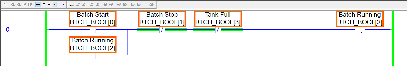
In the rung above, the difference is that the tags are specified within an array. The tags are “BTCH_BOOL[0]”, “BTCH_BOOL[1]”, etc. The challenge here is two fold:
- The programer will be required to add comments in order to describe what the use case of the tag is. That’s what we see above the tags: “Batch Start”, “Batch Stop”, etc.
- By creating such a structure, the programmer is forced to allocate too much or too little memory for the number of tags required for the application.
The solution to the problems mentioned above are User-Defined Data Types.
Creating a UDT in RSLogix and Studio 5000
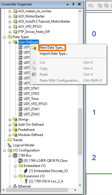
Under the Controller Organizer, Right-Click the “User-Defined” label and select “New Data Type…”
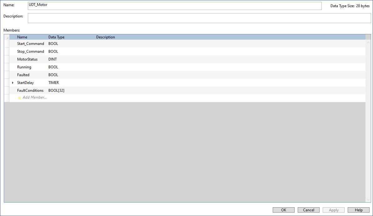
The screen above displays a basic implementation of a Motor structure. It’s important to note a few things:
- The UDT is composed of basic structures as discussed previously: BOOL, DINT, Timer.
- The UDT contains an Array (BOOL[32]). There is no restriction on arrays within UDTs.
- The UDT structure allows nesting of other UDTs inside (Note: this does not mean that you should nest structures excessively.).
Creating a UDT Instance in RSLogix and Studio 5000
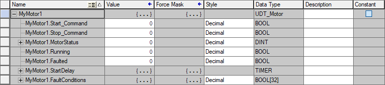
Once the UDT is in place, it’s possible to create a tag of that Data Type just like we would otherwise. Here’s an example of a tag that has been created of type “UDT_Motor” as defined above.
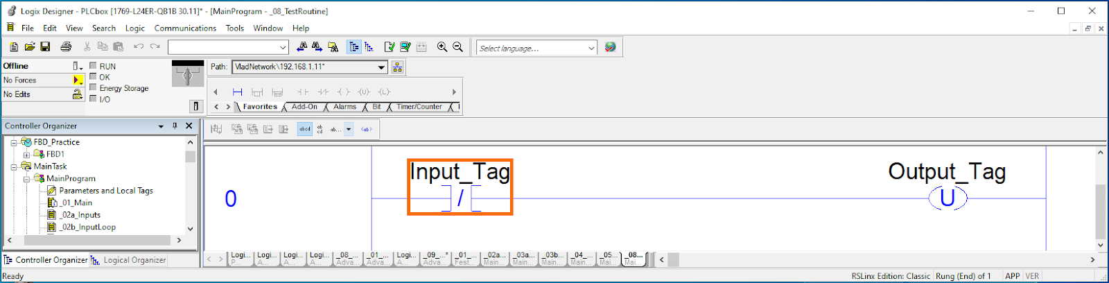
Once added to ladder logic, the tags within a rung would look as follows:
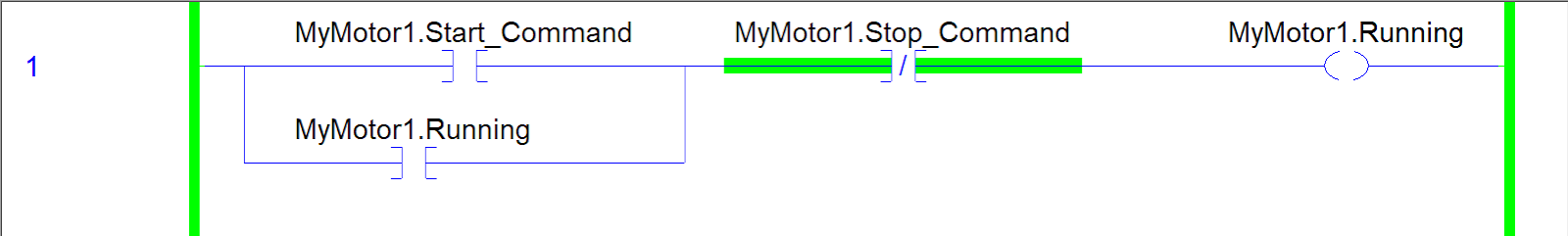
Notice that in this case, it’s clear without additional comments to which motor the tags belong to and what they execute.
Conclusion on PLC Data Types and UDTs
It’s important for PLC programmers to be acquainted with data types, how much memory they occupy on the device and how they are utilized in programming. We’ve covered data types from basic to advanced including User Defined Data Types that allow the user to create custom data structures and enhance their programming.
