An Introduction to DeviceNet Industrial Networks

Introduction
It’s not necessary to be an Engineer to understand the importance of communication. Just as a team leader needs to communicate to all the members of a team to relay instructions and reciprocally gather information from them, any automation system needs communication to and from all parts in the system.
There are a lot of different mediums, protocols and types of industrial networks in use today. Each one has its own benefits, drawbacks and intended use. DeviceNet is widely known as one of these industrial networks. Although this may be a fairly old network and not used as much for new installations as in previous years, it is not obsolete yet as it still has a large install base and is definitely worth investing time to understand and be able to implement.
What is DeviceNet
DeviceNet is a Control Area Network (CAN) that utilizes the Common Industrial Protocol technology. The medium by which the network is connected to devices is via a round or flat ribbon network cable. The devices connected to the network are called nodes. The maximum number of nodes in a single network are 64.
DeviceNet has been commonly used due to its simplicity and cost-effectiveness. What makes it easy to use and install is due to the fact that a common network is used to connect multiple devices, Inputs and Outputs. A common trunk cable is used as the network backbone and thinner cables / drops are connected between the trunk and the nodes. This is less cabling as opposed to a Remote I/O rack with multiple cables going to different devices from a central location. A common DeviceNet application may look as depicted in the following figure.
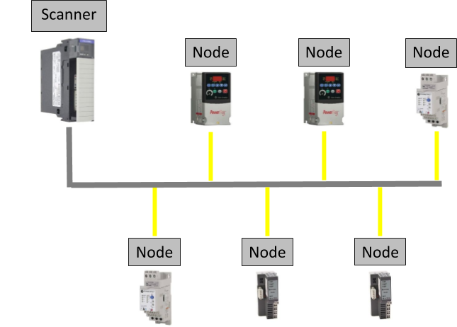
The Scanner, as used in the figure for an example, is connected to the PLC through the backplane.
It’s worth noting that there are other types of Scanners, like a CN2DN that is not connected to the backplane but is converted to ControlNet before ultimately communicating to the PLC but serves the same function. The Scanner is also connected to all the Nodes in the network. From this explanation, it can be seen that the Scanner will give all the Input communications of the connected devices to the PLC when the PLC requests for Inputs and will send the output to the devices as received from the PLC.
RSNetworx for DeviceNet
The interface used, from Rockwell Automation’s range of applications, to work on a DeviceNet network is RSNetworx for DeviceNet.
This application is used to add nodes to the network, configure devices, monitor the different parameters and aids in fault finding when a fault is present, or the devices on the network is not performing as expected.
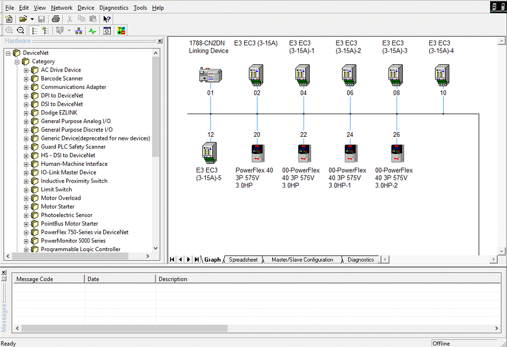
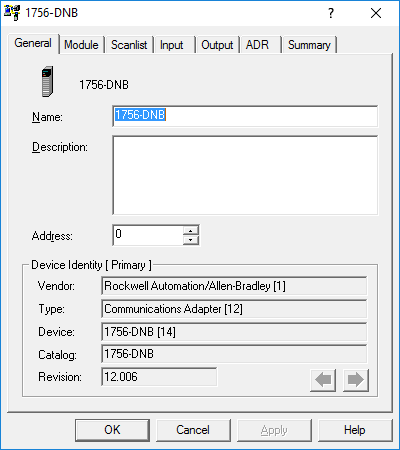
By double clicking on the Scanner Module, which in this case is Node 01 the 1788-CN2DN, a window pops up showing the general properties of the Scanner.
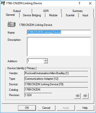
From this screen the Name, Description and Node address may be changed. The valid node addresses range from 0 – 63. Manufacturers will typically set the default node address of a device to 63. In most cases, this should ensure that there are no clashes in the form of duplicate node addresses, when a new device is added to the network. There are a few different ways in setting a device’s node address. Some devices’ addresses are changed on the hardware itself. This may be in the form of two pots, one for the most significant digit (MSD) and the other for the Least significant digit (LSD), or in the form of five dip switches with each dip switch representing a decimal value that is added to the total node address value when switched on, as depicted in the following figure.

Other devices’ addresses are changed through software changes. This may either be on the interface (HMI) located on the device itself, or through RSNetworx for DeviceNet.
Downloading the EDS File
When a manufacturer designs a new device, it is done to perform a specific function. In performing this function, a device will typically send measured data in the form of output from the device (Input to the Scanner) and need instructions as inputs to the device (Output from the Scanner). To clearly indicate the parameters that are configurable for a device and the type/form of I/O the device needs or produces, the manufacturer creates an Electronic Data Sheet (EDS file). This is a simple text file that helps the application to identify the device and adds meaningful descriptions and configurable values to the parameters for us to understand, as can be seen in the following Notepad windows of an E3 electronic motor overload’s eds file.
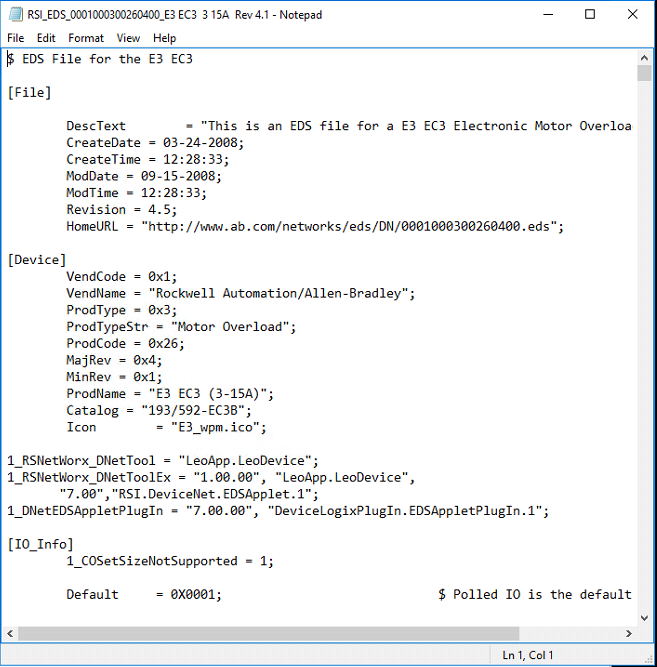
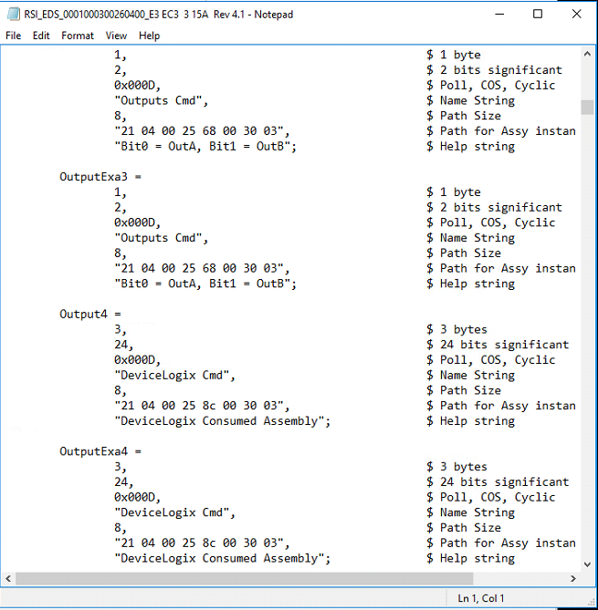
This small text file is an important piece of the puzzle, to install, configure and commission a device on the network. Typically, an eds file may be downloaded from the manufacturer’s website.
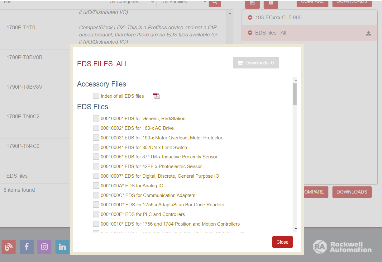
Once an eds file is downloaded for a device the following procedure may be followed to install it in RSNetworx for DeviceNet.
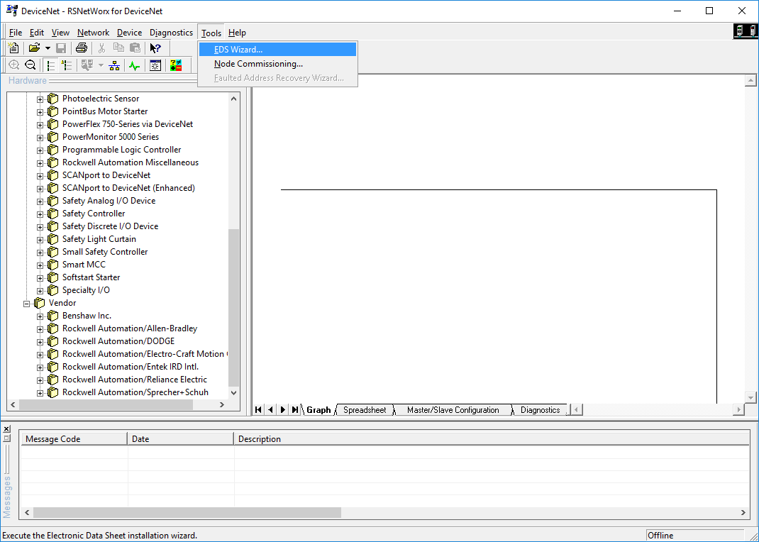
Setting up the EDS Wizard
- Click on Tools in the Menu and select EDS Wizard.
- The EDS Wizard window opens.
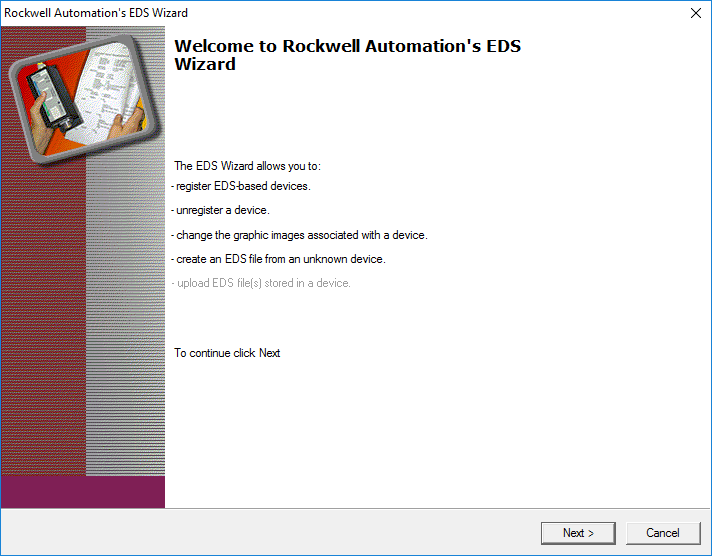
- Click Next.
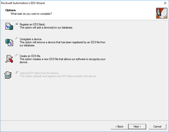
- Select ‘Register an EDS file(s)’ and click Next.
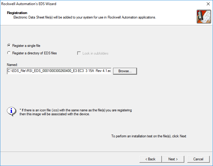
- Browse to where the EDS file has been saved.
- In this case a single file has been selected, so ‘Register a single file’ radio button must be selected.
- Click Next.
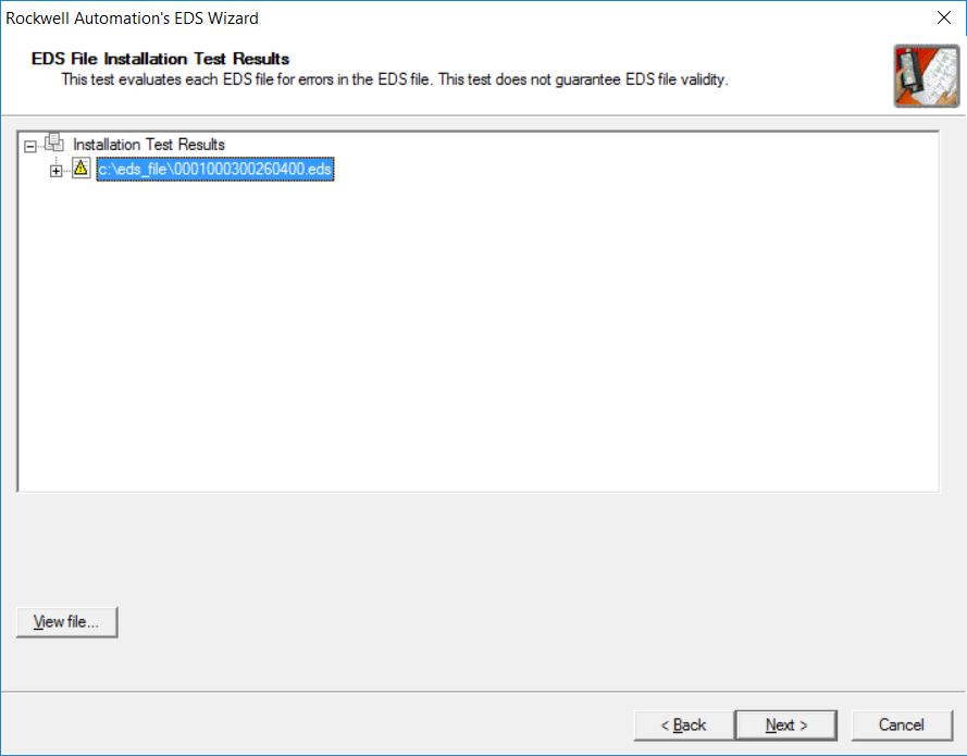
- Click Next
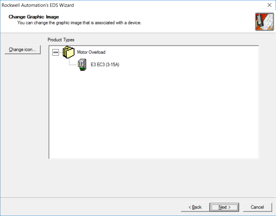
- In this window it displays the icon that is associated with the EDS file that is going to be loaded.
- Click Next
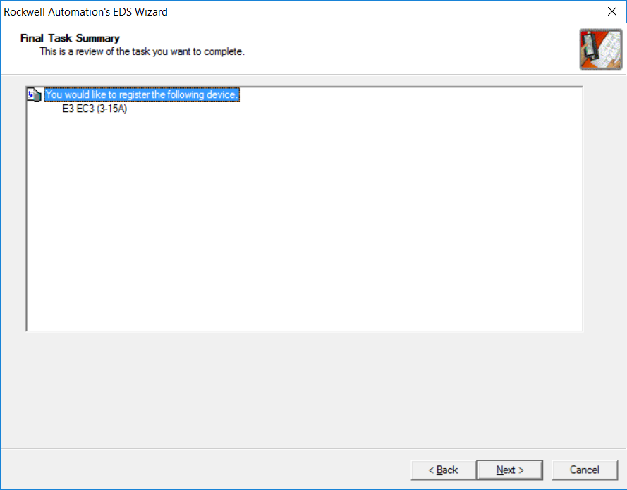
- Click Next
- The EDS file has successfully been loaded and the device is now available to add to the network.
Memory Mapping
To be able to make full use of any technology, it is best to find out how the puzzle fits together and understand it. Understanding how the data of one device fits into the registers of another device makes it possible to manipulate it, either to conform to a defined standard, only use the data necessary to save space, or organize it in a form that makes logical sense. To explain what is meant by these statements, let’s continue with the E3 Motor Overload. From the user manual, it can be seen that there are a few different input and output assemblies available to be chosen from for this device.
The Input assembly is specific data made available in the device and arranged in a predefined order.
Note: Some devices make it possible for the user to customize the chosen data and order it is arranged in.
As an example, the following figure shows one of the possible input assemblies that may be chosen when using an E3, as taken from ‘Rockwell Automation Publication 193-UM0021I-EN-P’.
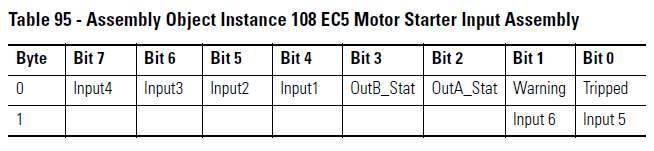
As seen in this figure, this input assembly is called the ‘Motor Starter Input Assembly’. The column on the left, shows that 2 Bytes of Data are produced if this assembly is chosen. The function of every bit is also described, for example, Byte 0: Bit 0 can be used to detect if the motor controlled/monitored by the E3 has tripped. This in turn can be mapped to the input register of the scanner. The input registers can then also in turn be used in the PLC for modifying a piece of control logic or taken through an OPC server/client combination to a SCADA/HMI system to be displayed.
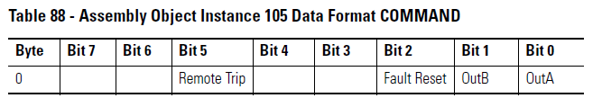
As the E3 device is not just for monitoring a motor, but also for controlling it, an output assemble can also be chosen according to the function the user should choose to perform with the device. For an output assembly example, let’s look at the following:
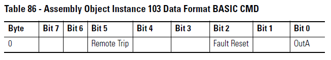
Here the output assembly chosen is called ‘BASIC CMD’. This assembly consists of 1 Byte of data. To use an arbitrary bit from this assembly for example, Byte 0: Bit 2 ‘s description shows ‘Fault Reset’. This means that, if mapped to the scanner’s Output registers, logic can be programmed in the PLC to reset the motor after a trip condition has occurred. Apart from logic, a command may also be sent from a SCADA/HMI to the PLC, which in turn will output the command to the Scanner, relaying the instruction to the E3 device and ultimately resetting the trip condition.
Now that Input and Output Assemblies have been discussed, it is useful to know how the data is written into the registers of the Scanner and how ‘Mapping’ occurs. To understand this concept, look at the following diagram displaying how this is done.
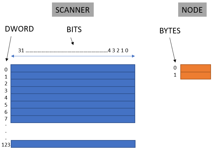
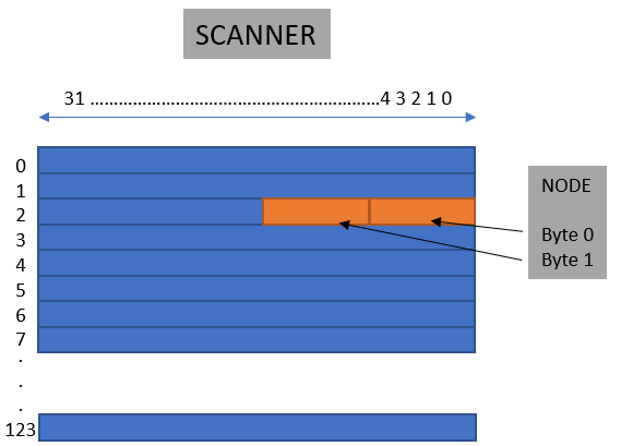
The Scanner’s Input Memory/Registers are depicted in blue. There are 124 DWORDs in total. One DWORD is 32 bits. The node with it’s Data is shown in Orange. To use this data, it must be mapped into the Scanner. If the data from the Node should be mapped into DWORD 2, starting at bit 0 in a contiguous format, it will look as follow:
Adding and Configuring a Node Offline
With all the prerequisite knowledge in place, an offline file may now be created. In this offline file a new scanner will be added, together with the E3 Motor overload that has been used as example throughout this article.
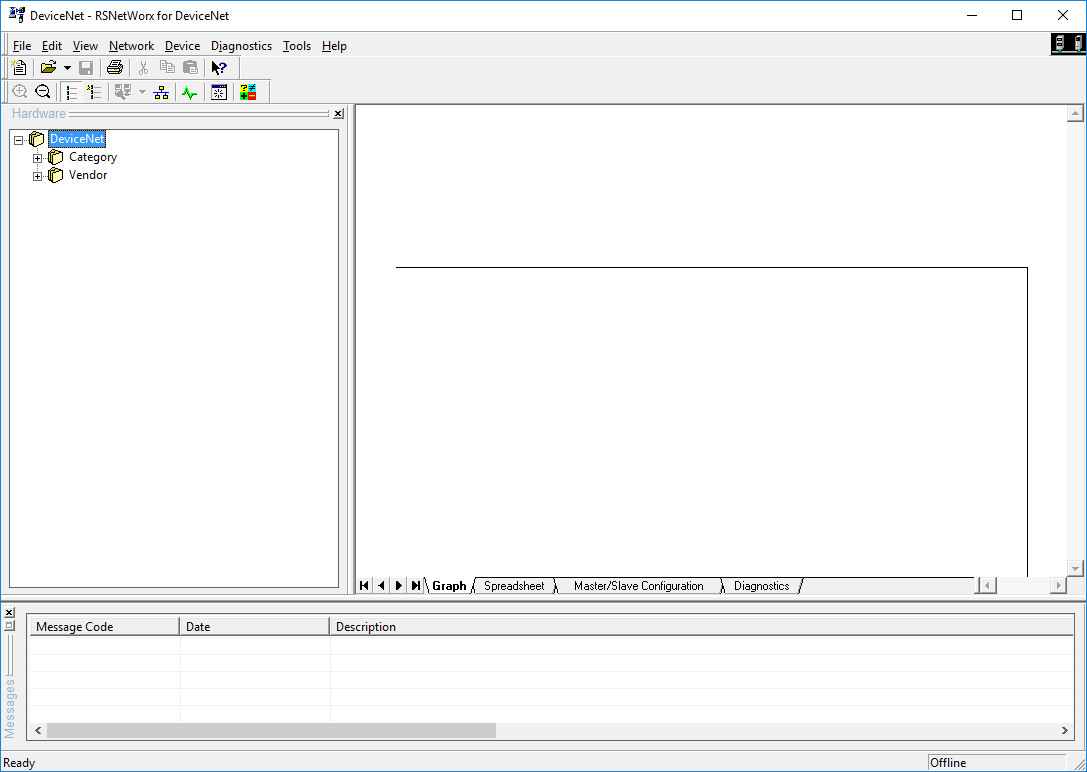
Step 1 – Open RSNetworx for DeviceNet
- Click on the Windows start button
- Browse to RSNetworx for DeviceNet and open the application
Step 2 – Add the Scanner
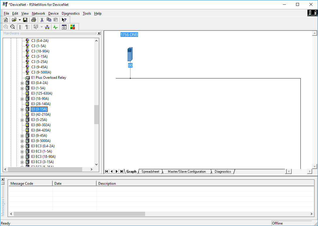
- Browse through the Hardware tree to the correct device or alternatively, right-click in the tree area.
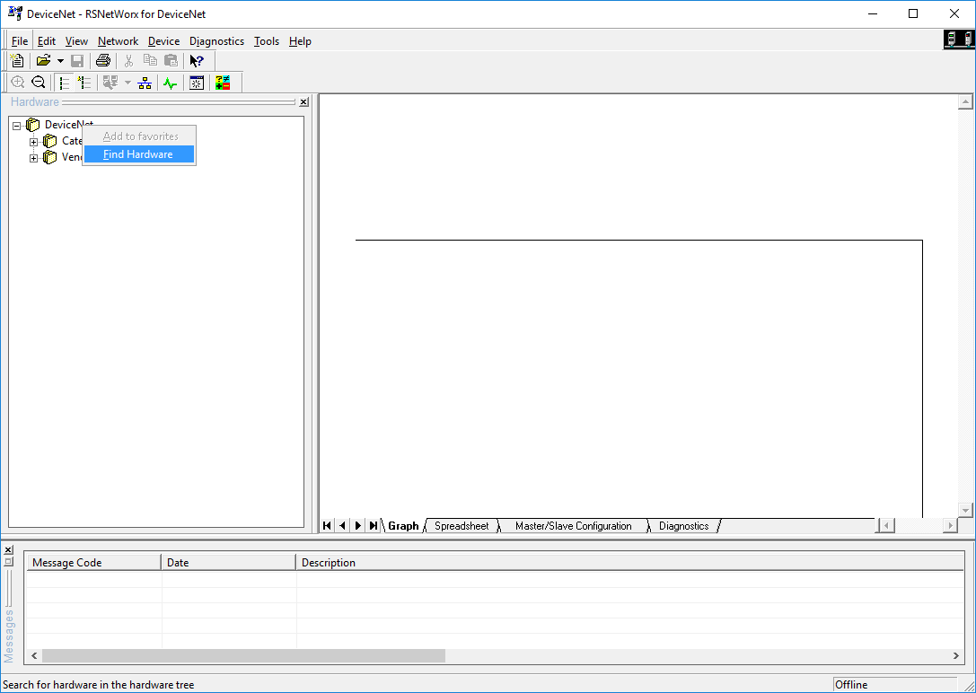
- Click on Find Hardware
- In the ‘Find Hardware’ window that opens, type the following: ‘1756-DNB’
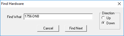
- Click ‘Find Next’
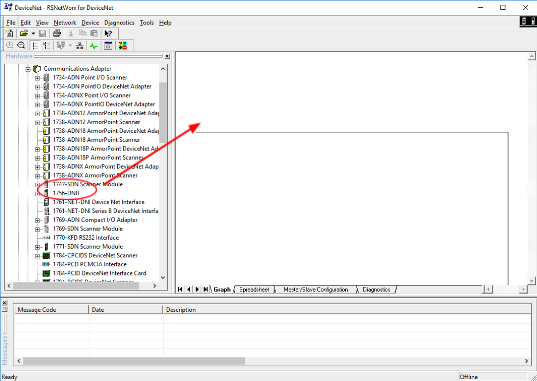
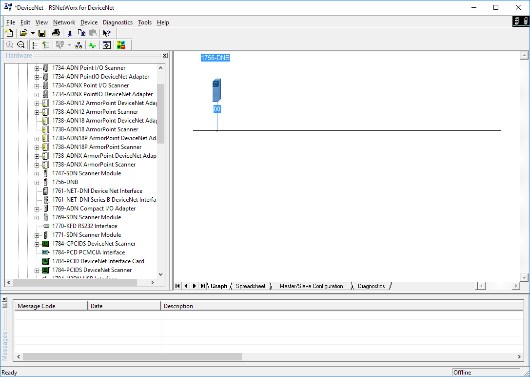
- The tree expands around the area where the device can be found.
- Click on the device and drag and drop into the Graph area.
Step 3 – Add the E3 Motor Overload
- The same sub-steps that was followed in the previous Step may be done here as well.
- Right-click in the Hardware tree.
- Select ‘Find Hardware’
- Type ‘E3’ and click ‘Find Next’
- Drag and drop ‘E3 (3-15A)’ device into the Graph area.
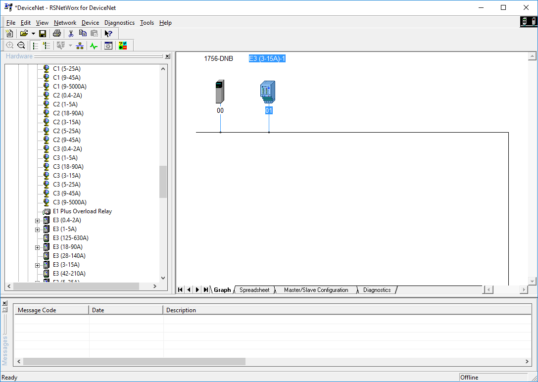
Up to this point, the devices have been loaded into the network configuration. In the following steps the device must be loaded to the Scanner’s scanlist. By adding the device to the scanlist, the Scanner is instructed to actively communicate with the device, by reading the Input data and writing the output data to it. Furthermore, the data from the device must also be mapped into the Scanner’s memory as was discussed in the previous section.
Step 4 – Configure the E3 Motor Overload
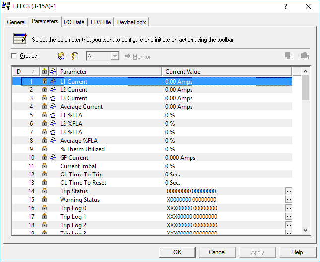
- Double click on the E3 device.
- Select the ‘Parameters’ tab.
- Scroll down to Parameter ID: 60
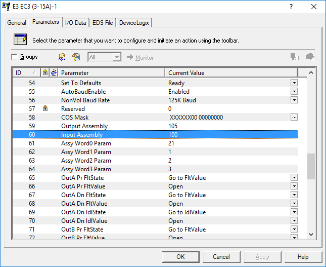
Parameter 60, as displayed above, is the Input Assembly. Parameter 59 is the Output Assembly. The selections made for the different assemblies are 100 for the Input Assembly and 105 for the Output Assembly. Referring to the user manual for the E3 Motor Overload, it can be seen what data these assembly selections consist of.
Note: Different assemblies may be chosen, but for the purpose of this part of the tutorial these assemblies will be used.
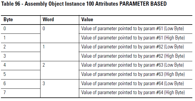
The user manual shows that this Input Assembly consists of 8 bytes in total. The data that fills up this assembly is a combination of Parameters 61, 62, 63 and 64, each filling two bytes of data. To verify what these parameters mean and what the assembly consists of the following inspections may be carried out:
- Select the ‘I/O Data’ tab.
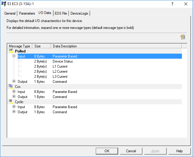
From first inspection, it’s seen that the data is available as Polled, Cos (Change of State) and Cyclic. Note: The explanations of these different Message Types are outside the scope of this article and may be attained by further reading in the help files of RSNetworx for DeviceNet. The first two bytes only displays ‘Device Status’, so may seem ambiguous what data is contained within this word. By further inspection, it can be seen to what data Parameters 61 – 64 are pointing too.
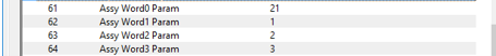
This means that these parameters actually consist of the data contained in parameters 21, 1, 2 and 3.
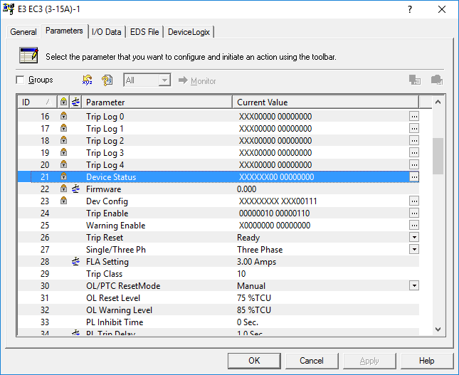
Parameter 21 is the Device Status, as was seen on the ‘I/O Data’ tab.
- Click on the ellipsis, on the right of Parameter 21’s ‘Current Value’ field.
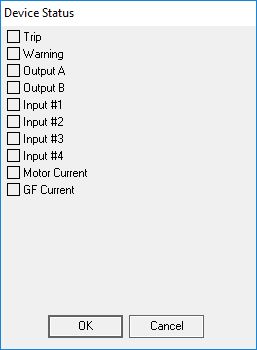
- The ‘Device Status’ window opens, displaying the data contained within the first Word/2 Bytes.
- Scroll to the topmost Parameters.
- Parameters 1, 2 and 3 are displayed. This is the three different Currents of the three different phases connected to the motor.
To identify what the output Assembly consists of, in this case is an easier task. This can be done purely by inspecting the user manual.
Step 5 – Configure the Scanlist
- Double click on the Scanner (1756-DNB, Node 00)
- Click on the Scanlist tab
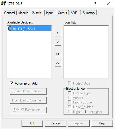
- The E3, located in the Node 1 position, is available to be added to the Scanlist.
- Leave the ‘Automap on Add’ tick box ticked and press the ‘>’ button.
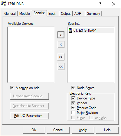
- Click on the ‘Edit I/O Parameters…’ button
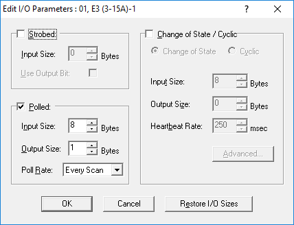
- Here the Message Type may be selected, as well as the Input / Output Sizes.
- All these default selections correspond with the configuration in the E3 device, so click ‘OK’.
Step 6 – Map the Device’s I/O to the Scanner
- Select the ‘Input’ tab.
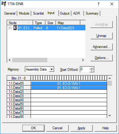
The E3’s input data was automatically mapped to the first open space available in the Scanner in a contiguous format. This is convenient as far as network configuration may be concerned, but some coding techniques will be needed to split the data in the PLC to get the data into an understandable format. Instead of segregating the data in the PLC, it may be done in this configuration.
- While Node 01 is selected, click on ‘Unmap’.
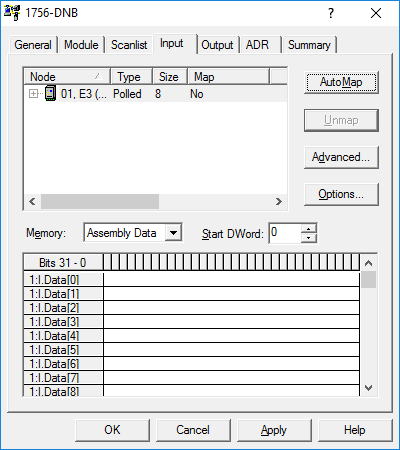
- The data has been unmapped from the Scanner’s memory.
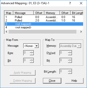
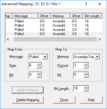
- Click on ‘Advanced’
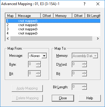
- The ‘Advanced Mapping’ window opens.
- Here the data may be segregated logically, so that each Word is mapped into its own DWord slot, so that it starts from Bit 0.
- In the ‘Map From’ field, select the following:
- Message: Polled
- Byte: 0
- Bit: 0
- In the ‘Map To’ field, select the following:
- Memory: Assembly Data
- DWord: 0
- Bit: 0
- In the ‘Bit Length:’ selector, select 16
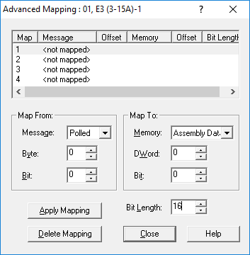
- This will map the first 2 bytes (Byte 0 and 1), from the device to the Scanner’s DWord 0.
- Click ‘Apply Mapping’
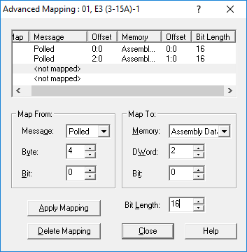
- Highlight the 2nd entry in the Map view.
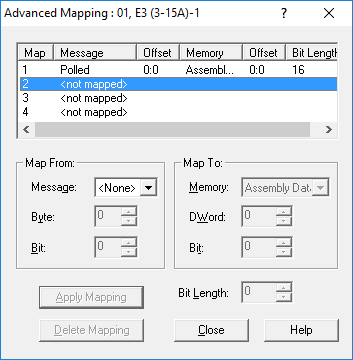
- In the ‘Map From’ field, select the following:
- Message: Polled
- Byte: 2
- Bit: 0
- In the ‘Map To’ field, select the following:
- Memory: Assembly Data
- DWord: 1
- Bit: 0
- In the ‘Bit Length:’ selector, select 16
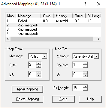
- This will map Bytes 2 and 3, from the device to the Scanner’s DWord 1.
- Click ‘Apply Mapping’
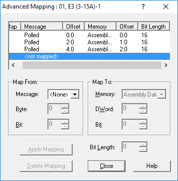
- Highlight the 3rd entry in the Map view.
- In the ‘Map From’ field, select the following:
- Message: Polled
- Byte: 4
- Bit: 0
- In the ‘Map To’ field, select the following:
- Memory: Assembly Data
- DWord: 2
- Bit: 0
- In the ‘Bit Length:’ selector, select 16
- This will map Bytes 4 and 5, from the device to the Scanner’s DWord 2.
- Click ‘Apply Mapping’
- Highlight the 4th entry in the Map view.
- In the ‘Map From’ field, select the following:
- Message: Polled
- Byte: 6
- Bit: 0
- In the ‘Map To’ field, select the following:
- Memory: Assembly Data
- DWord: 3
- Bit: 0
- In the ‘Bit Length:’ selector, select 16
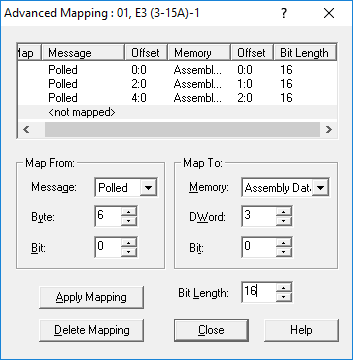
- This will map Bytes 4 and 5, from the device to the Scanner’s DWord 2.
- Click ‘Apply Mapping’
- The Advanced Mapping of the Input from the device is now complete.
- Click ‘Close’
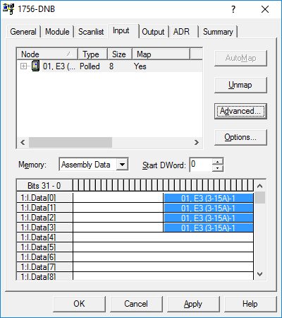
- The Input mapping has been split up for this device, each into its own DWord slot in the Scanner.
- Select the ‘Output’ tab.
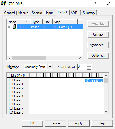
- The Auto mapping of the Output was also done to the first available space. In this case, this will suffice as there is only 1 Byte of data made available by the E3 device.
- Click on ‘Apply’.
- The Mapping is now finished.
- Click ‘OK’.
Conclusion
This is only an effective starting point with DeviceNet as an industrial network. A basic offline configuration was attempted in this piece, with some exposure to advanced features. I want to urge you as the reader to do further reading on the topic and investigate how the configuration will differ when it’s done in an online scenario. ‘Play’ with different devices on the network, separating the data in different ways in the Advanced mapping and even go look into how to use Message instructions in RSLogix to use other parameters in your code that is not exposed through the different Input and Output Assemblies.
