Cookies are important for this site to function properly, to guarantee your safety, and to provide you with the best experience. By clicking OK, you accept all cookies. For more information, please access our Privacy Policy.
Table of Contents
Tutorials / 
Enhancing Siemens Drive Safety Using SLS Functionality
Advanced

Enhancing Siemens Drive Safety Using SLS Functionality

Siemens
TIA Portal
Servo Motors
Variable-Frequency Drives

‍Introduction

This tutorial offers a comprehensive guide for utilizing the 'Safely Limited Speed' (SLS) functionality while operating SINAMICS G120D and G115D distributed drives with PROFIsafe through the PROFINET network. Applications confronted with situations with potential hazards necessitate the utilization of the 'Safely Limited Speed' functionality to ensure the drive continues operating reliably and without compromise.

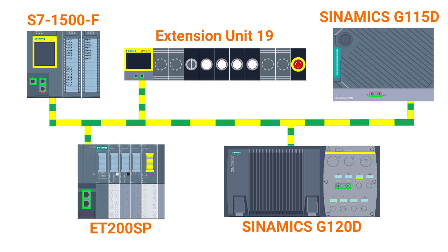
The subject matter of this application example revolves around a machinery setup featuring: A) The drive is safely positioned inside a guarded space. B) The drive is placed in an area that falls outside the protected zone. C) Our safety measures include a fence that encloses the drive and an entrance door protected by a safety contact, restricting access to the drive’s movable parts. D) Emergency stop button.

Engage with Figure 1.1, and you will gain insights into the components featured within this application example in the TIA Portal project.

Figure 1.1: Enhancing Siemens drive safety - Automation task overview

Prerequisites

What you will need to follow along with this tutorial:

Hardware Configuration

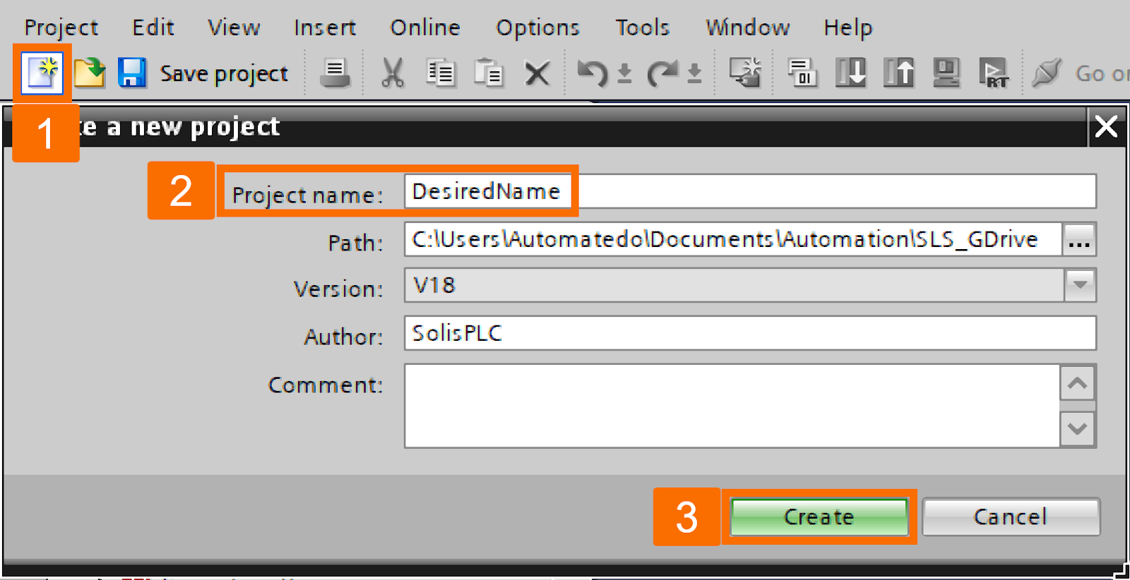
Incorporating the safety PLC is your first step. Within the TIA Portal, you will begin by initiating a new project and assigning it a descriptive name.

Figure 2.1: Enhancing Siemens drive safety - Creating a Tia portal project

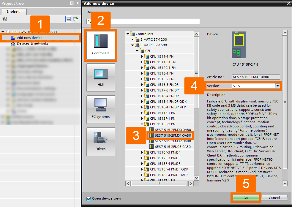
Begin by adding a new device to the project. From its window, you'll choose the desired safety PLC. Then, select the necessary data and communication protection settings.

Figure 2.2: Enhancing Siemens drive safety - Adding a fail-safe PLC to the project

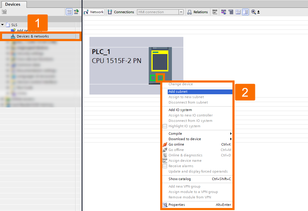
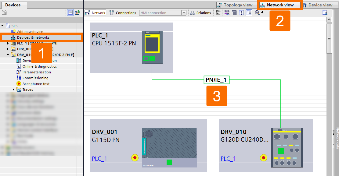
Double-click 'Devices and networks' and then switch to the 'Network view' to introduce a PROFINET subnet to your network setup.

Figure 2.3: Enhancing Siemens drive safety - Generating a Profinet subnet in the network

Proceed by incorporating a drive into the project. Select the 'G115D PN' drive and then rename it to your desired preference. Firmware version 4.7.14 or above is necessary to access the SLS functionality on the G115D drive.

Figure 2.4: Enhancing Siemens drive safety - Adding Sinamics G115D drive to the project

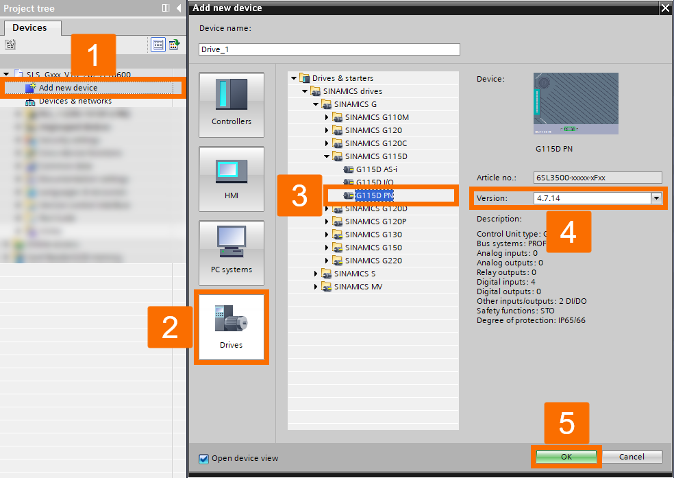
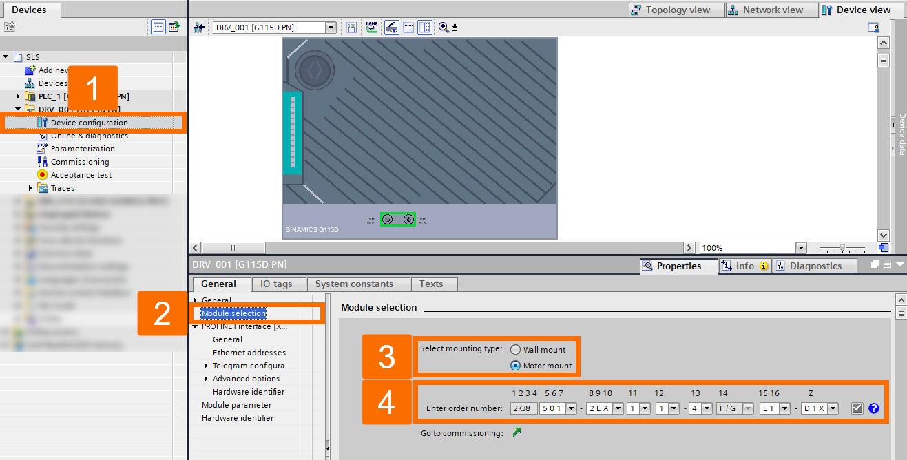
Continue by specifying the drive details. Start with the 'DRV_001' drive, then access the 'Device configuration' section. Next, move on to 'Module selection' and select the suitable drive specification for your requirements.

Figure 2.5: Enhancing Siemens drive safety - Configuring Sinamics G115D module selection

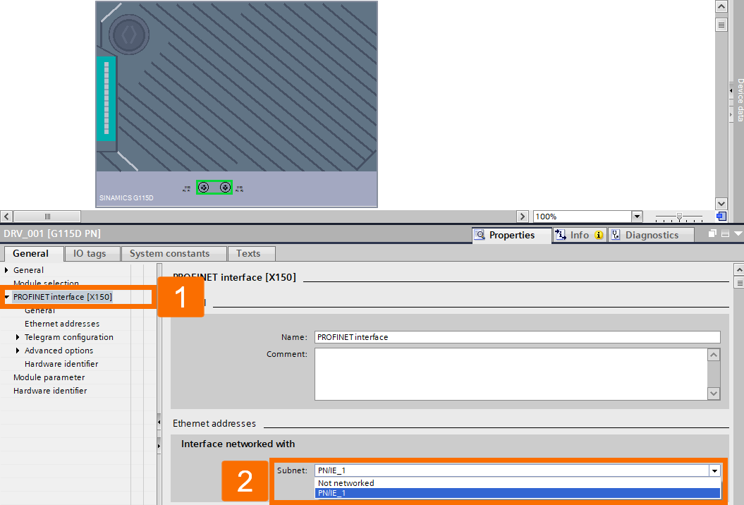
Establish a connection between the drive and the PROFINET network by configuring the PROFINET interface, ensuring it is networked with the desired PN/IE_1 connection.

Figure 2.6: Enhancing Siemens drive safety - Configuring Sinamics G115D Profinet interface

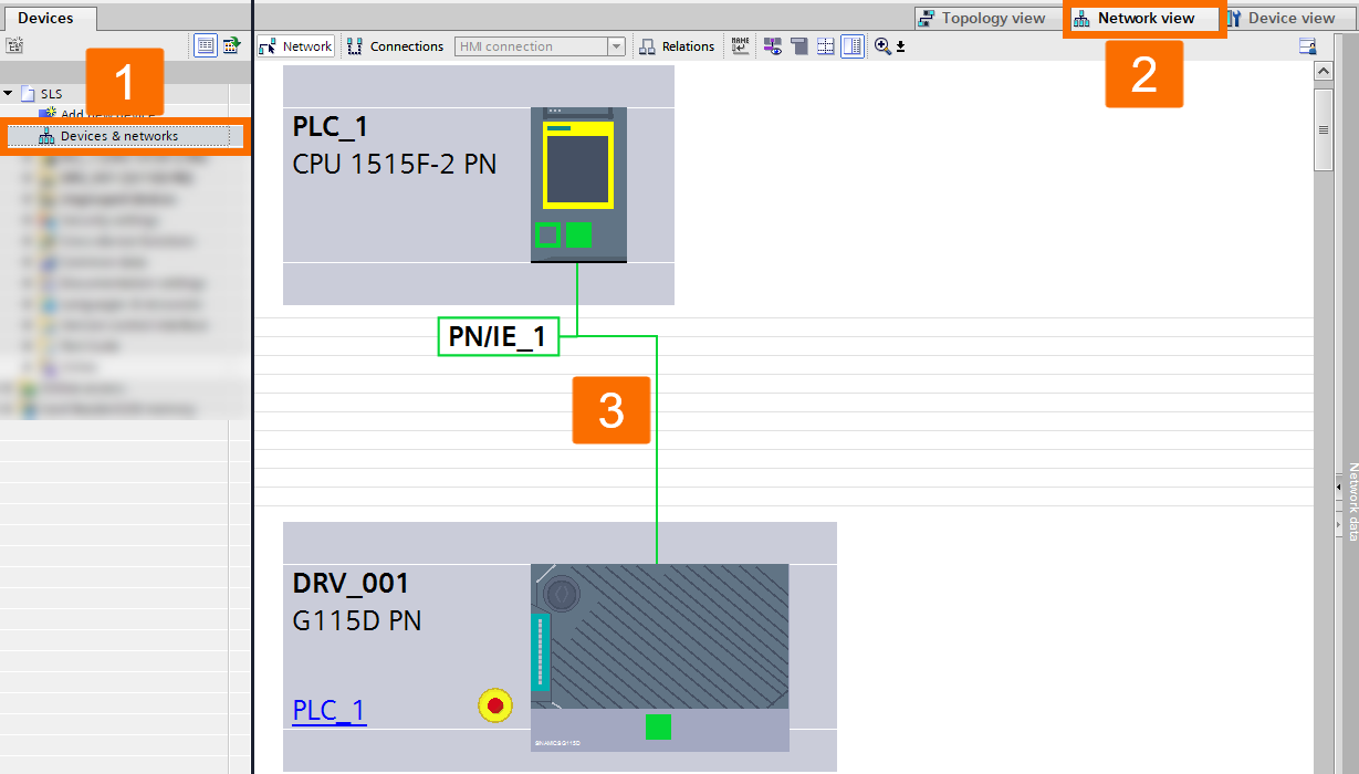
Link the drive to the PLC by accessing the 'Devices & networks' section. From there, go to 'Network view,' select the corresponding IO controller, and pick 'PLC_1 with PROFINET interface_1' for the connection.

Figure 2.7: Enhancing Siemens drive safety - Establishing Profinet connection between PLC and G115D drive

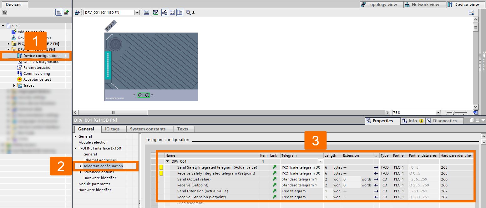
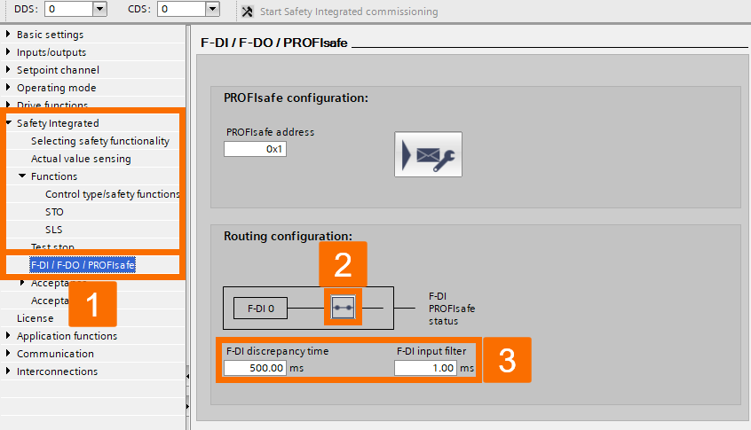
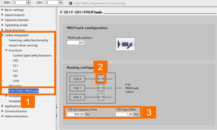
Let's make changes to the telegram configuration. Under the DRV_001 drive, access the 'Device configuration.' From there, navigate to 'Telegram configuration' and add a new telegram. Finally, include the 'PROFIsafe telegram 30' for safety integration. If you require the use of the drive fail-safe digital input (F-DI), consider switching to the PROFIsafe telegram 900 rather than the PROFIsafe telegram 30. As a result, the PLC safety program can evaluate the safety input, incorporating inputs from a protective door safety switch or an E-stop push button.

Figure 2.8: Enhancing Siemens drive safety - Telegram configuration of Sinamics G115D drive

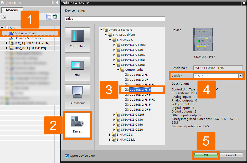
To incorporate the G120D drive into your project, double-click the 'Add new device' to pop up its window. Select the G120D drive and then rename 'Drive_1' as 'DRV_010'. You should know that the SLS functionality of the G120D is specifically designed to work only with safety control units marked as 'CU...-F'.

Figure 2.9: Enhancing Siemens drive safety - Adding Sinamics G120D drive to the project

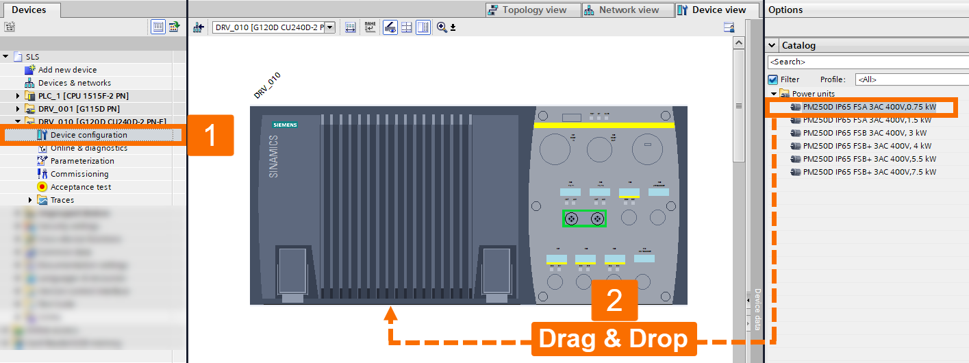
Proceed with specifying the drive details. Locate the DRV_010 drive and navigate to 'Device configuration.' Next, access the 'Hardware catalog' and drag the necessary power unit to the designated area. After you're done, return to the CU unit.

Figure 2.10: Enhancing Siemens drive safety - Adding the required power unit for the Sinamics G120D drive

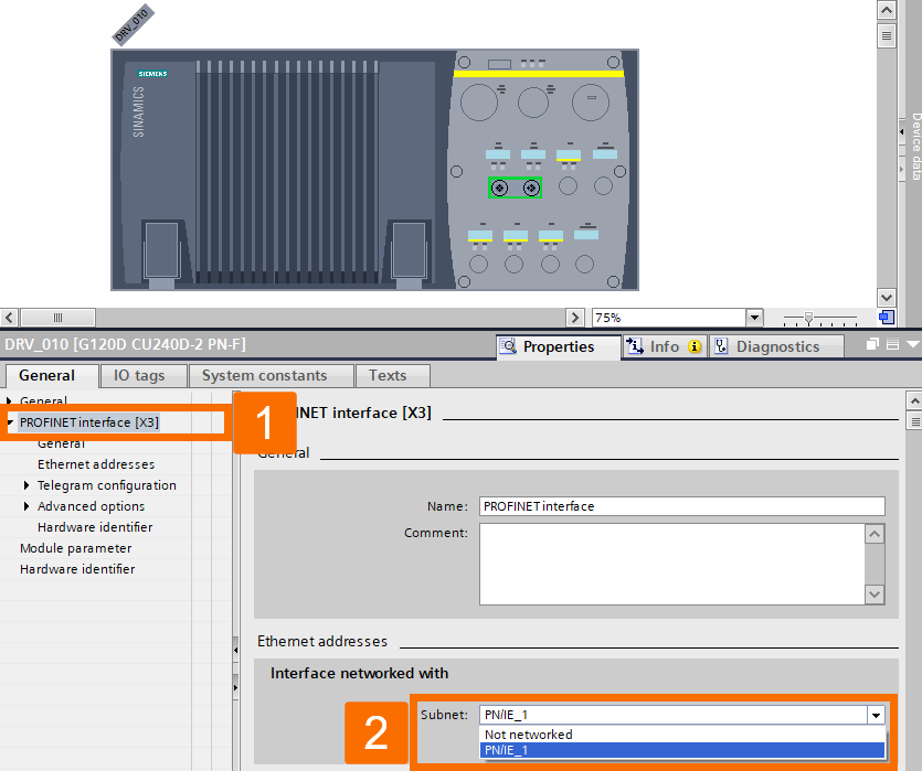
Establish a connection between the drive and the PROFINET network by utilizing the PROFINET interface. Choose the interface that is connected to PN/IE_1.

Figure 2.11: Enhancing Siemens drive safety - Configuring Profinet interface of the Sinamics G120D drive

To associate the drive with the PLC, go to 'Devices & networks.' From there, access the 'Network view,' choose the corresponding IO controller, and pick PLC_1.PROFINET with interface_1.

Figure 2.12: Enhancing Siemens drive safety - Adding Sinamics G120D drive to Profinet network

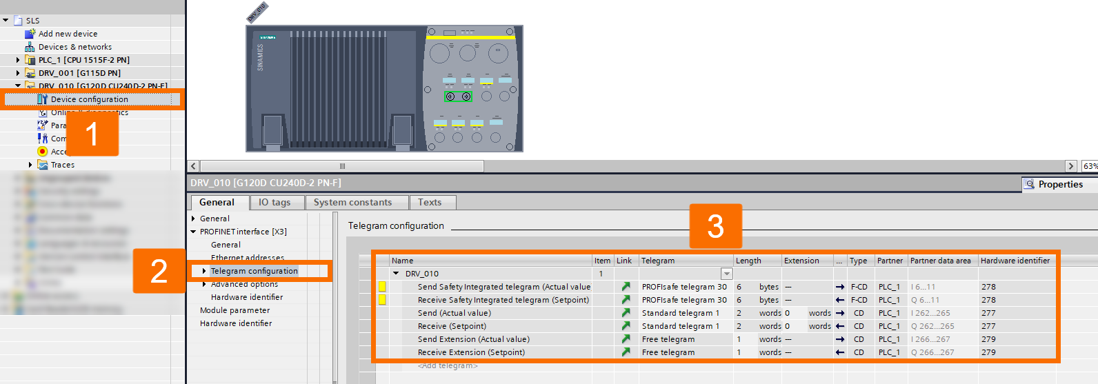
Make changes to the telegram configuration by accessing the 'Device configuration' for the DRV_010 drive. Then, navigate to the 'Telegram configuration' section, add a new telegram, specifically a safety-integrated telegram, and pick PROFIsafe telegram 30. Once more, go through the process with a variation: Add a new telegram, input the actual value, and specify it as a free-form telegram. Repeat the procedure with a slight modification: Add a new telegram, include the setpoint, and set it as a free-format telegram.

Figure 2.13: Enhancing Siemens drive safety - Telegram configuration of the Sinamics G120D drive

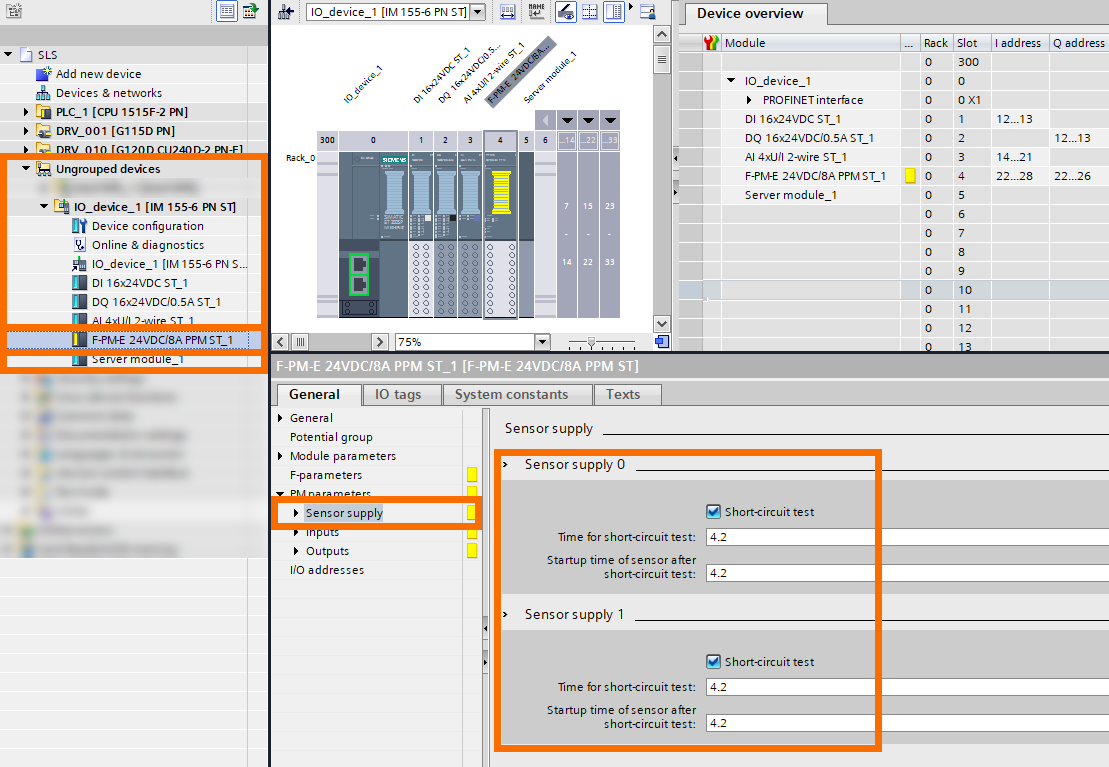
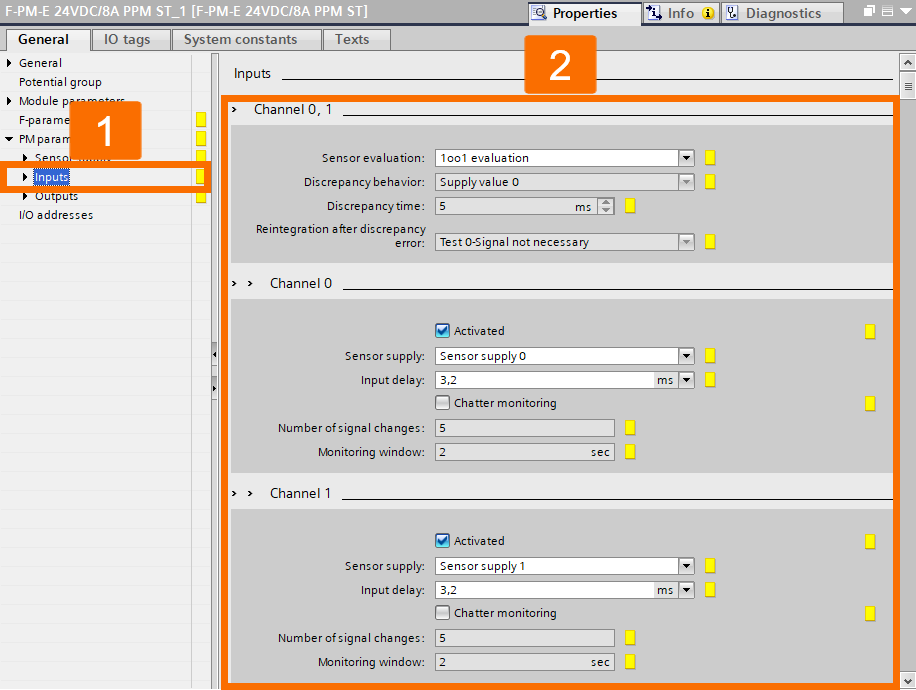
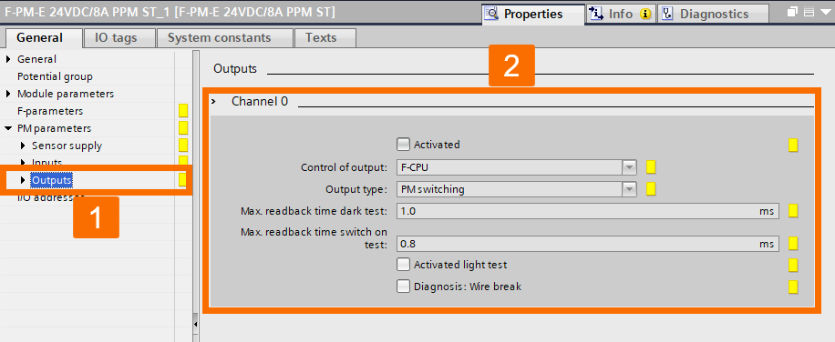
In this tutorial, detailed instructions for inserting individual modules of the ET200SP station are not provided. Only the configuration of safety card parameters for assessing the safety switch of a protective door will be explained in the following. When configuring the safety card, consider the details presented in the following three illustrations: Figure 2.14, Figure 2.15, and Figure 2.16.

Figure 2.14: Enhancing Siemens drive safety - ET200SP configuration - Sensor supply
Figure 2.15: Enhancing Siemens drive safety - ET200SP configuration - Configuring input parameters
Figure 2.16: Enhancing Siemens drive safety - ET200SP configuration - Configuring output parameters

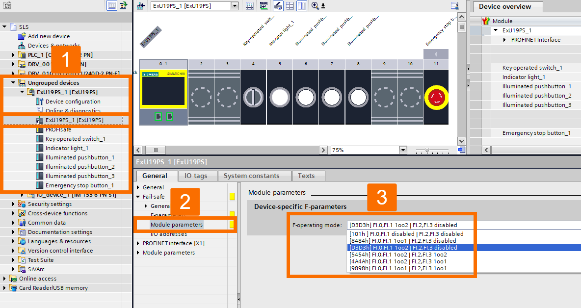
The same procedure for the Extension Unit station will be repeated, and only the configuration of safety parameters for assessing the emergency stop button will be explained. To properly set up the extension unit, refer to the guidance in Figure 2.17.

Figure 2.17: Enhancing Siemens drive safety - Extension unit configuration

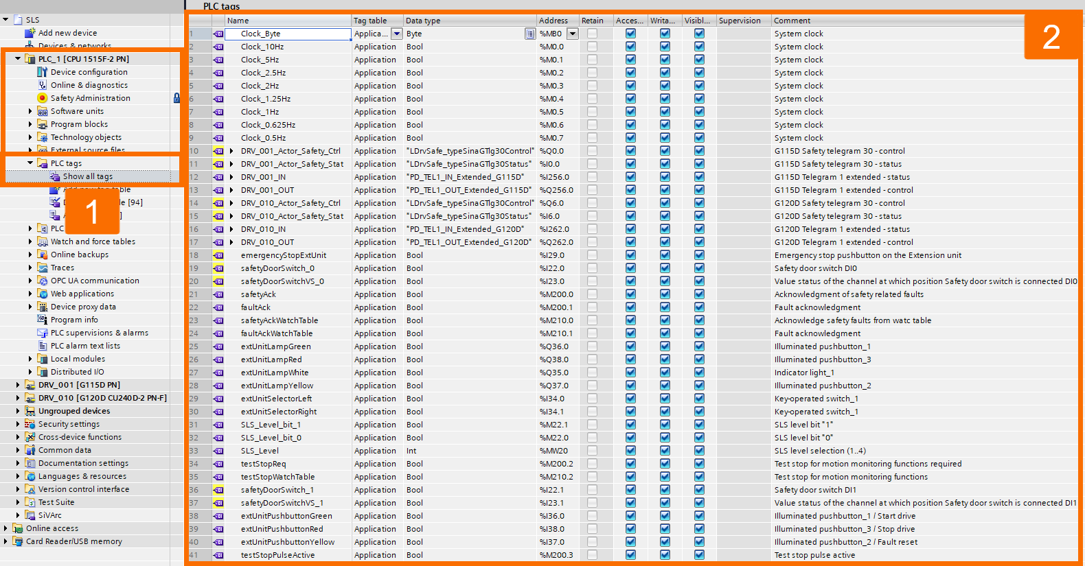
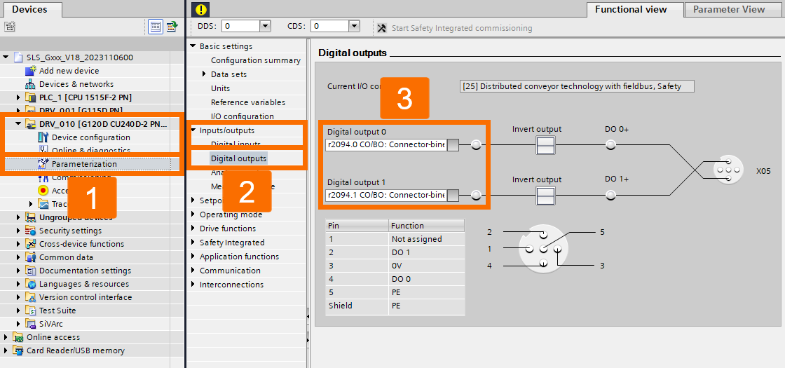
For improved clarity, it is suggested to assign symbolic addresses to physical inputs and outputs within the program for each device. Drives use data types that provide extended functionality for controlling and utilizing binary inputs and outputs, contributing to an optimized system workflow. To ensure proper functionality, it is essential to configure the parameters of the drives appropriately (refer to Figure 2.18).

Figure 2.18: Enhancing Siemens drive safety - Assigning symbolic addresses to physical input and outputs

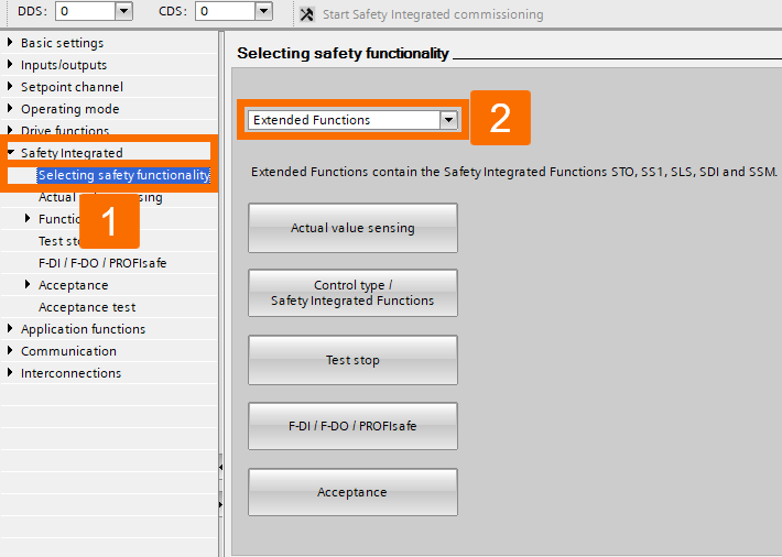
Drives Configuration

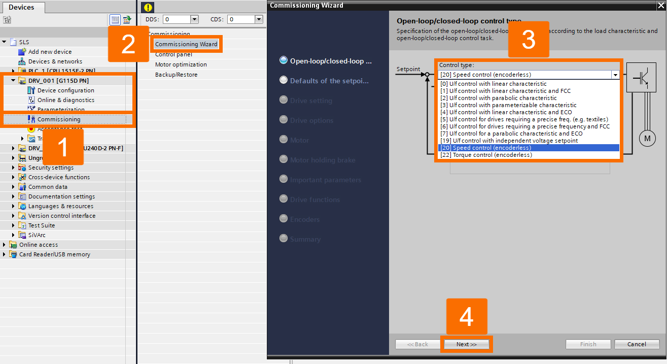
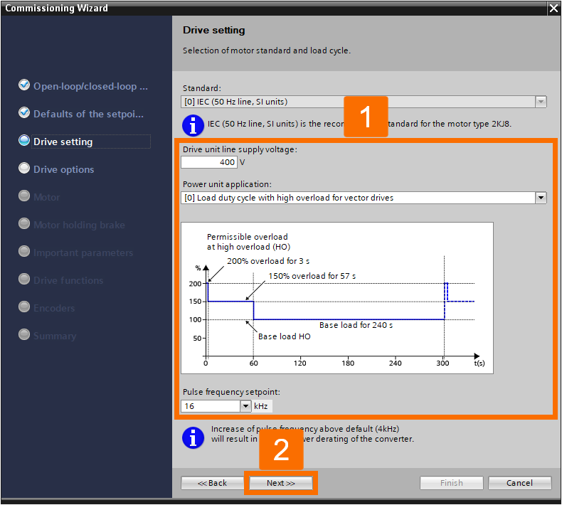
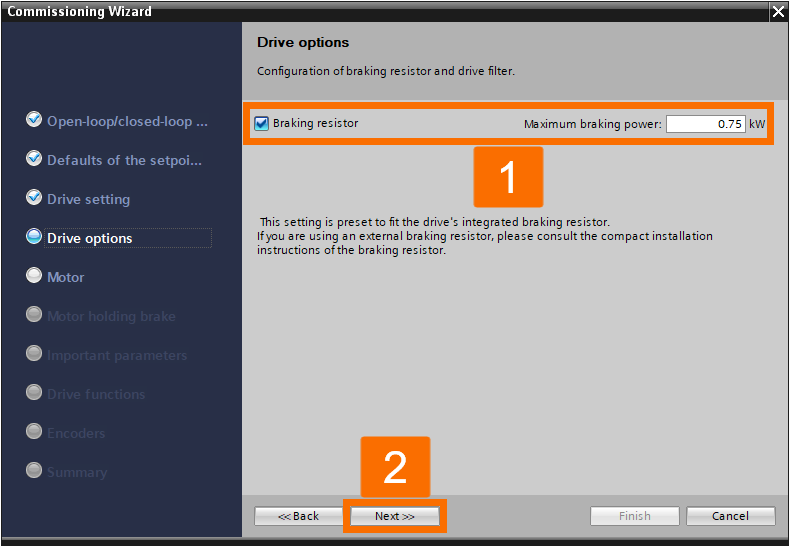
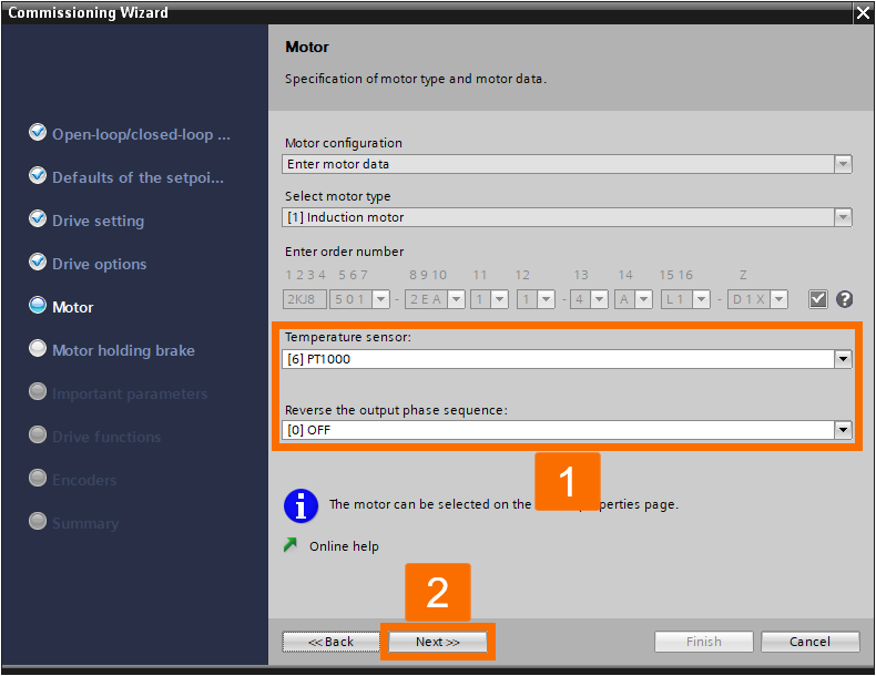
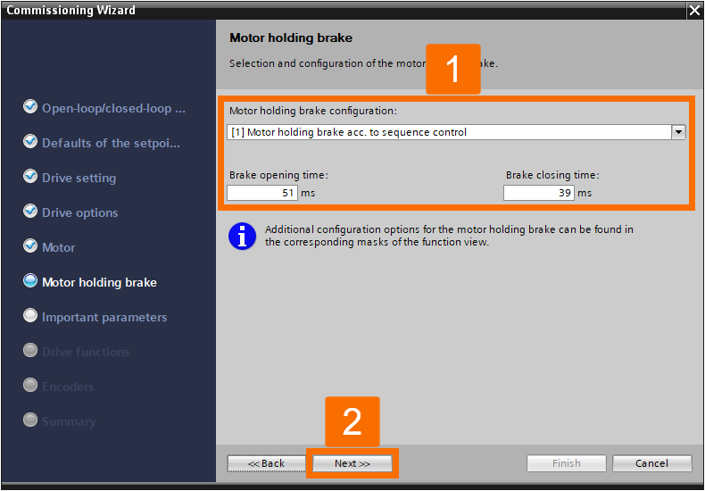
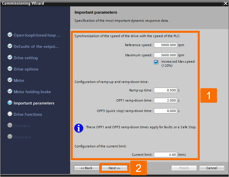
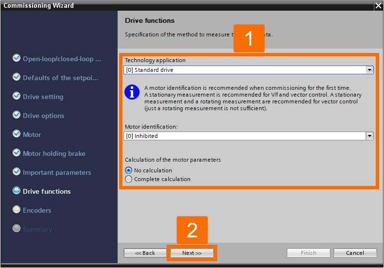
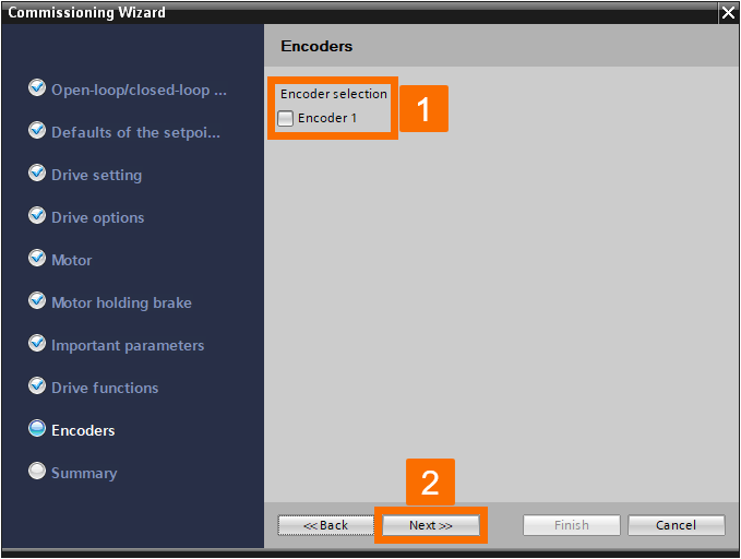
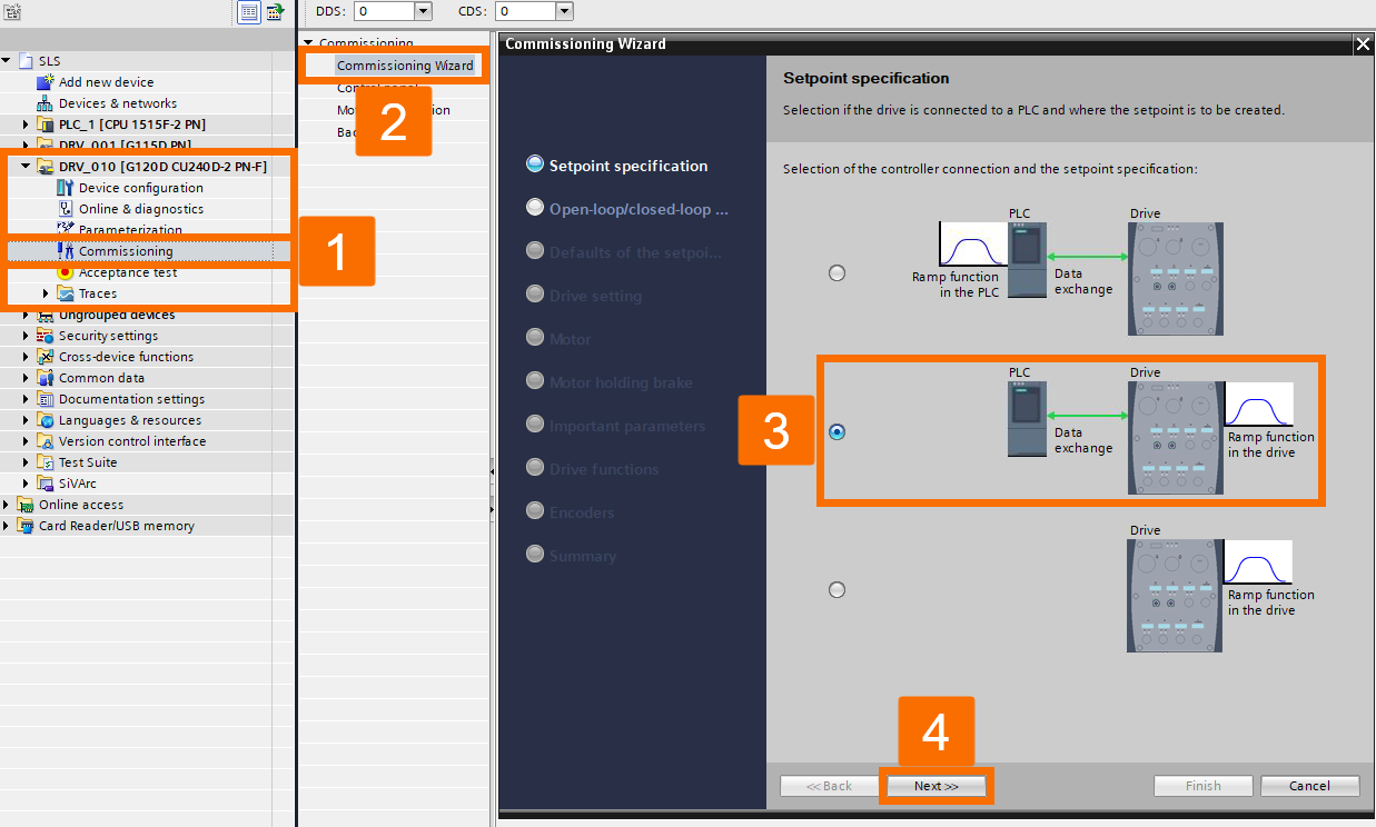
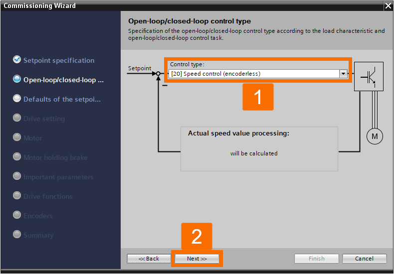
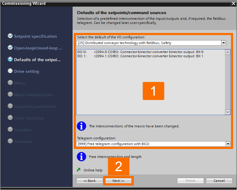
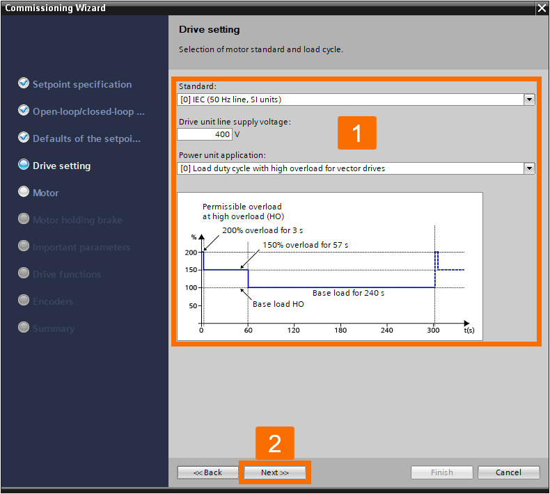
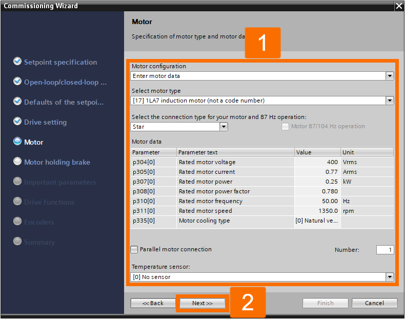
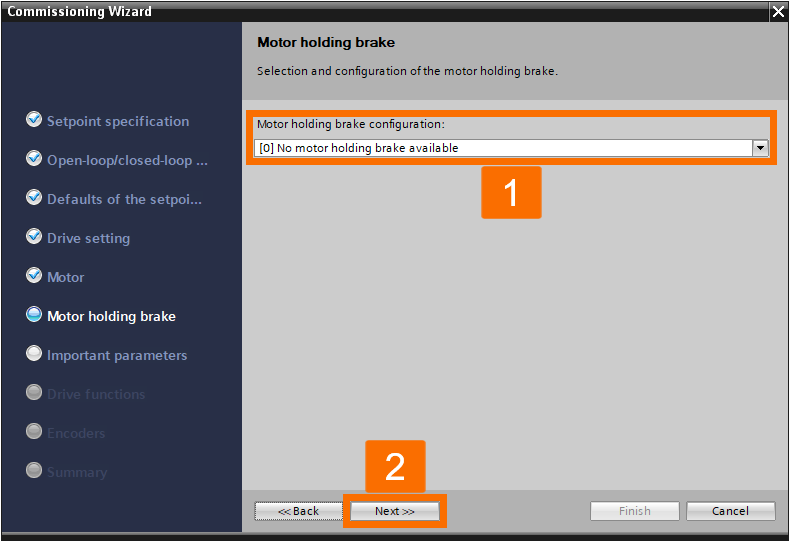
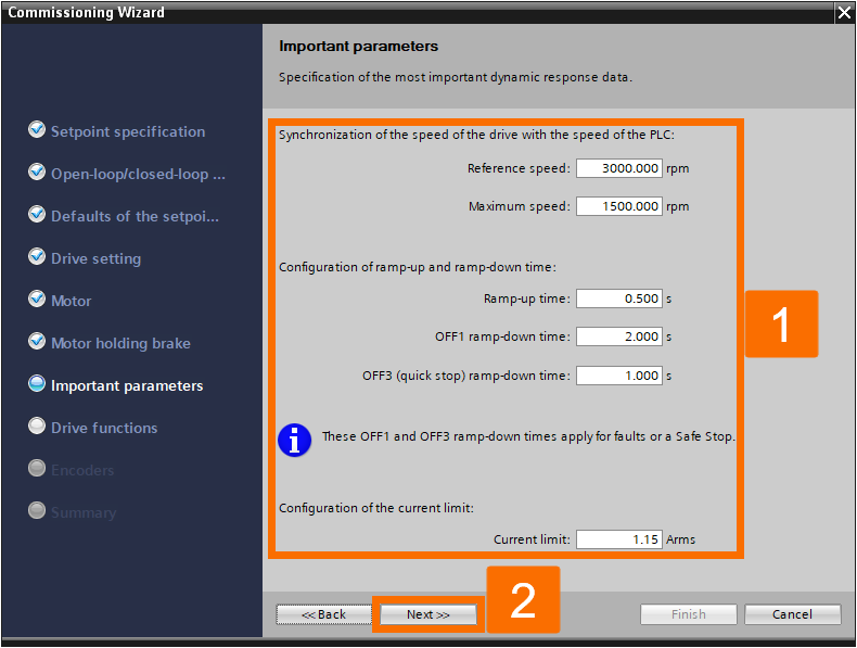
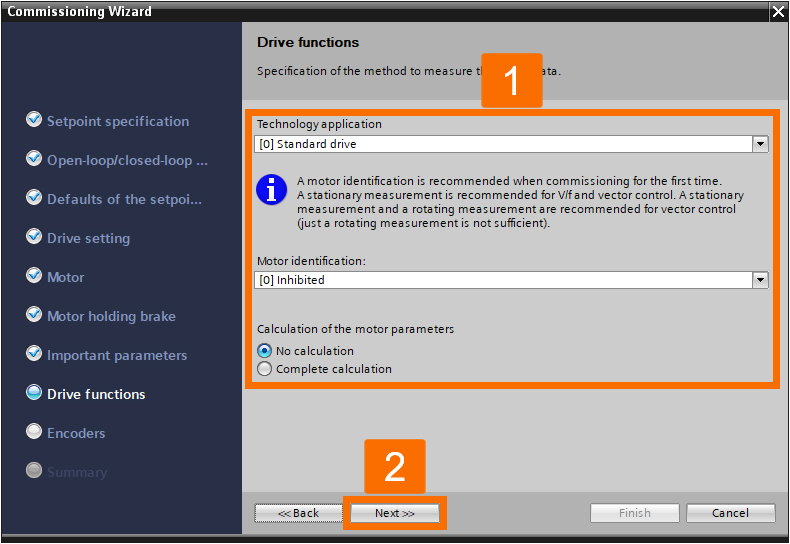
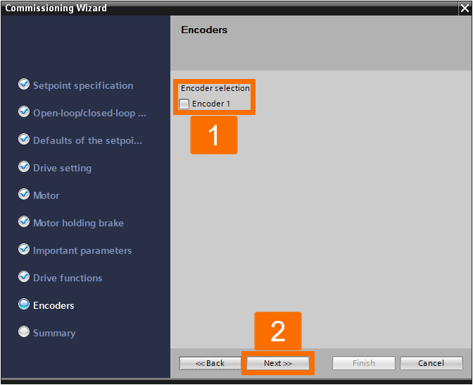
To carry out the commissioning process for the G115D drive, proceed with the commissioning wizard and fill out all the required data as shown in the Figures below.

Figure 3.1: Enhancing Siemens drive safety - Configuring G115D drive - Open-loop/Closed-loop control type
Figure 3.2: Enhancing Siemens drive safety - Configuring G115D drive - Defaults of the setpoints/command sources
Figure 3.3: Enhancing Siemens drive safety - Configuring G115D drive - Drive setting
Figure 3.4: Enhancing Siemens drive safety - Configuring G115D drive - Drive options
Figure 3.5: Enhancing Siemens drive safety - Configuring G115D drive - Motor specification
Figure 3.6: Enhancing Siemens drive safety - Configuring G115D drive - Motor holding brake
Figure 3.7: Enhancing Siemens drive safety - Configuring G115D drive - Important parameters
Figure 3.8: Enhancing Siemens drive safety - Configuring G115D drive - Drive functions
Figure 3.9: Enhancing Siemens drive safety - Configuring G115D drive - Encoder selection

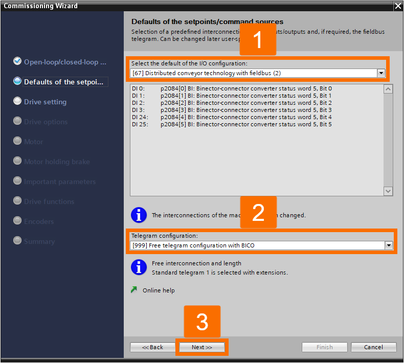
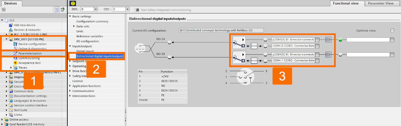
Start fine-tuning the G115D drive's settings. Proceed with the parametrization process for the drive. It is essential to adjust the bidirectional digital inputs/outputs in a manner that corresponds precisely to the described drive communication data types to achieve the correct functionality. In the event of any necessary changes, you can modify this setting to suit your specific requirements.

Figure 3.10: Enhancing Siemens drive safety - Configuring G115D drive - Bidirectional digital inputs/outputs

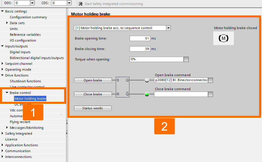
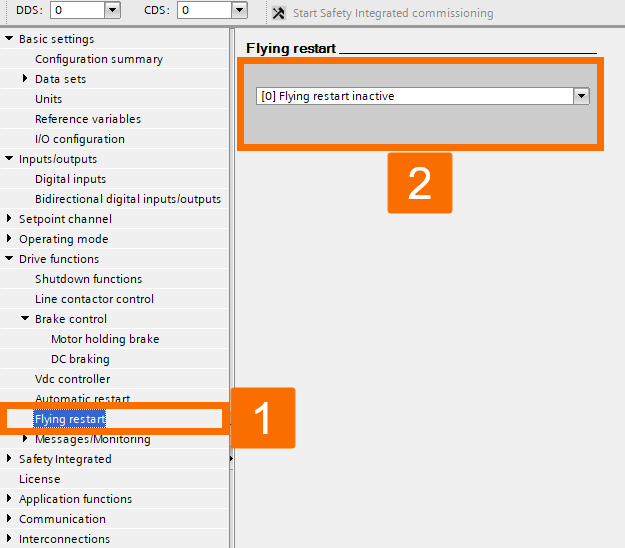
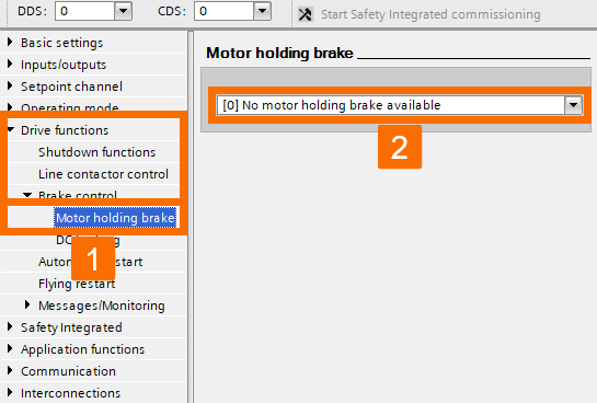
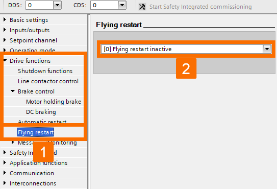
Keep progressing through the parametrization tree to access more drive settings and continue the configuration process. For visual guidance, refer to Figures 3.11 and 3.12. To maintain the highest level of safety and compliance in applications where extended safety functions are utilized, it is strictly mandated that flying restart in any form must not be employed.

Figure 3.11: Enhancing Siemens drive safety - Configuring G115D drive - Controlling brake
Figure 3.12: Enhancing Siemens drive safety - Configuring G115D drive - Flying restart

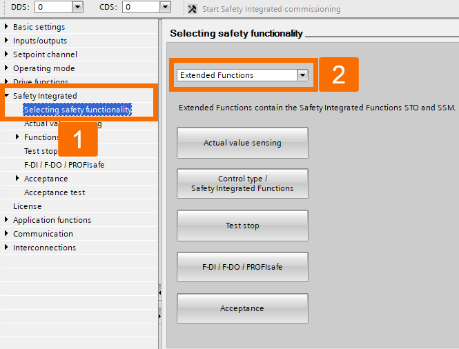
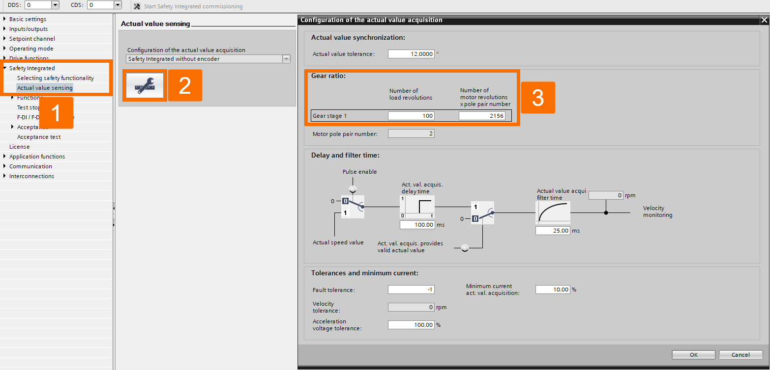
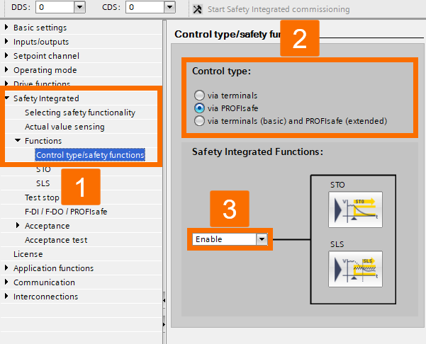
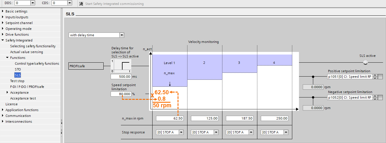
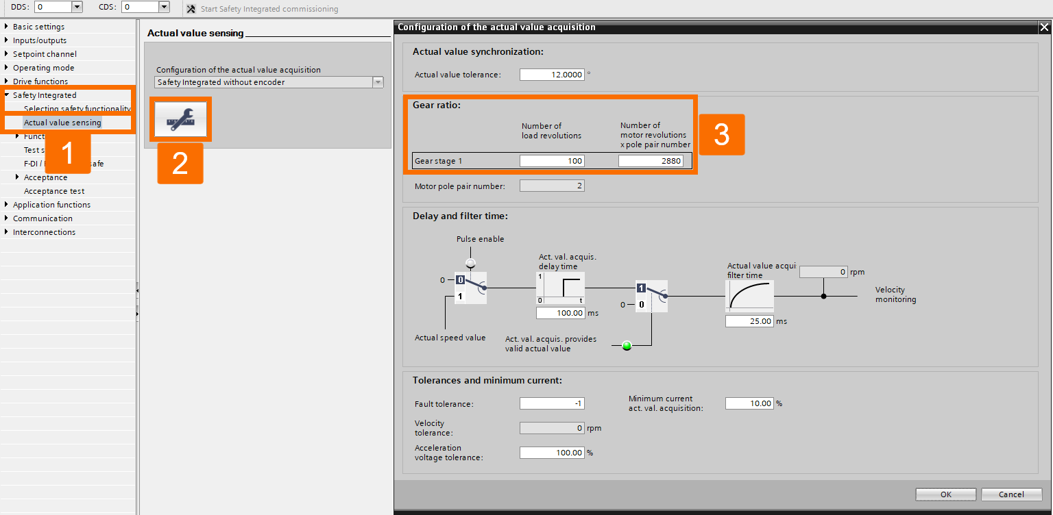
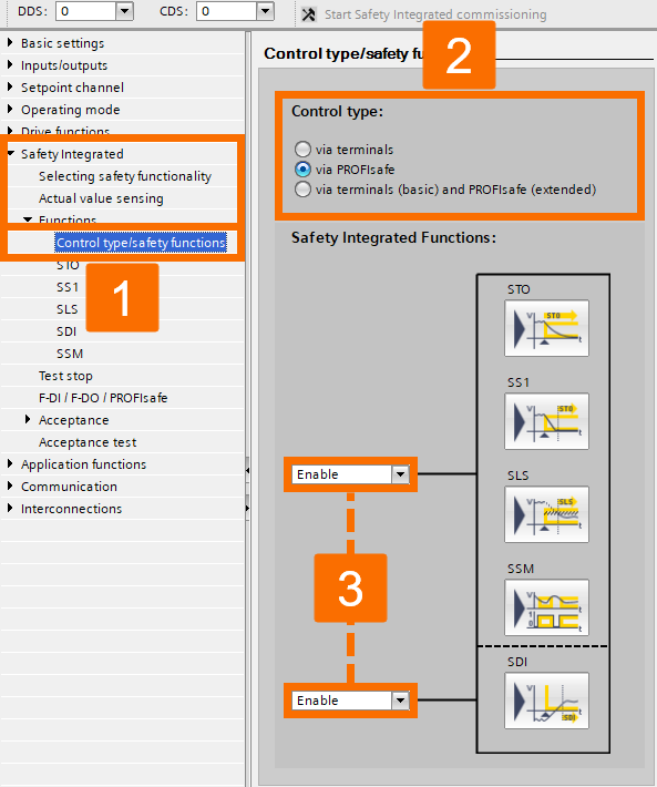
It is crucial to conduct the parametrization for safety-integrated systems offline to guarantee the consistency of the PLC software. Find detailed instructions in Figures 3.13, 3.14, 3.15, and 3.16. The careful configuration of the gear ratio plays a pivotal role in determining and fine-tuning the speed limits.

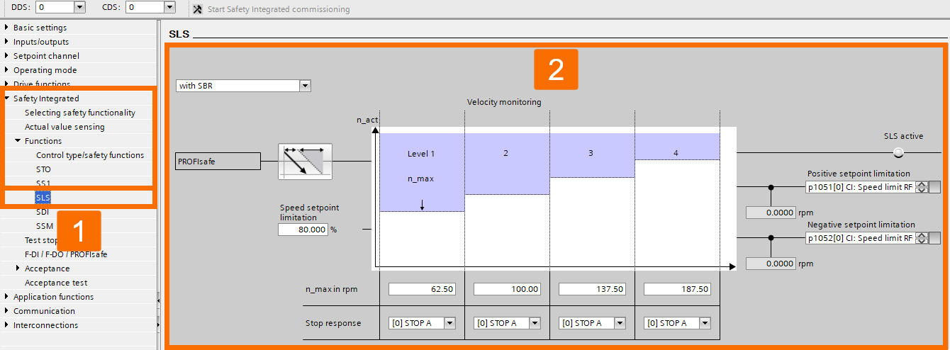
In the context of the 'Delay time,' the drive must adhere to a specified time constraint, ensuring a gradual reduction in speed until it reaches a value below the predetermined limit within a timeframe of 500 milliseconds.

To determine the speed setpoint limit on the side of the drive load, which comes into effect when SLS is activated, you can calculate it using the following method: Used setpoint limitation = Level maximum (X) Speed setpoint limitation. As a case in point, if Level 1 is activated, you have 62.50 (X) 80/100 = 50 rpm.

When the servo drive encounters obstacles like insufficient ramp-down time, external mechanical forces, or drive inertia, resulting in the inability to reach the speed limitation, the stop response characterizes the drive's reaction.

Figure 3.13: Enhancing Siemens drive safety - Configuring G115D drive - Selecting safety functionality
Figure 3.14: Enhancing Siemens drive safety - Configuring G115D drive - Actual value sensing for safety integration
Figure 3.15: Enhancing Siemens drive safety - Configuring G115D drive - Control type/safety functions
Figure 3.16: Enhancing Siemens drive safety - Configuring G115D drive - SLS configuration

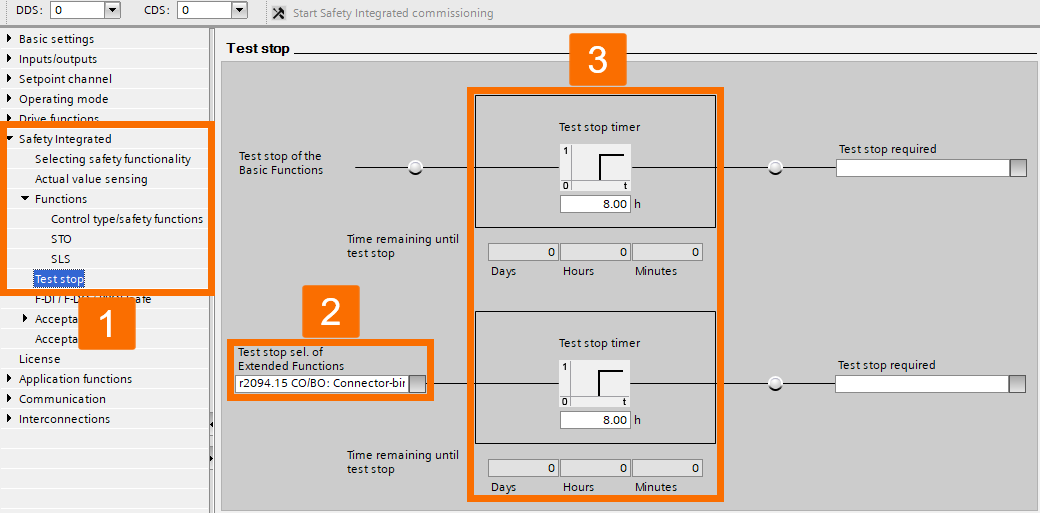
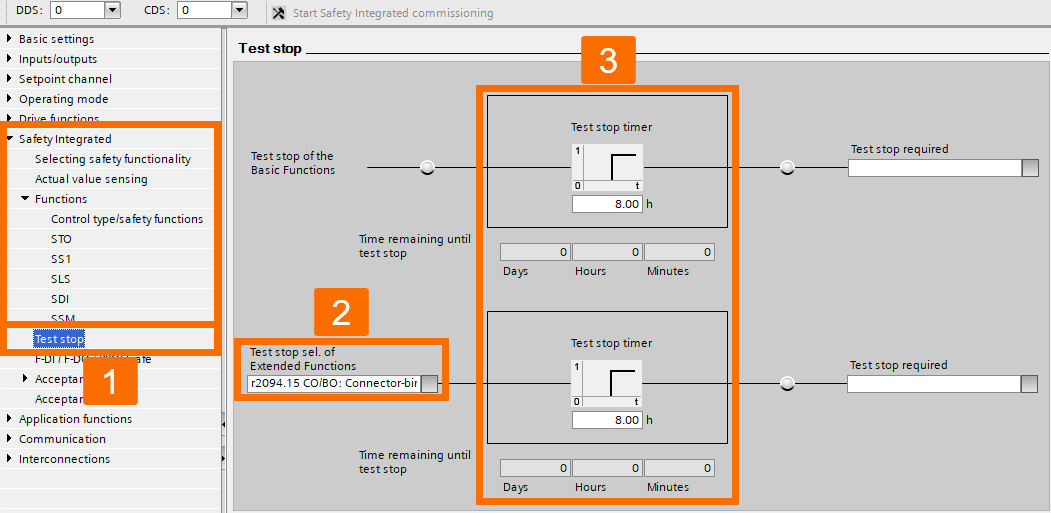
Create a signal link from the PLC and configure predetermined time settings to enable the functionality of the 'Test stop' feature. The test stop functionality can only be engaged when the drive has completely stopped its operation. Once the Test stop is activated, it effectively prevents any attempt to start the drive, ensuring operational safety and control.

Figure 3.17: Enhancing Siemens drive safety - Configuring G115D drive - Test stop

When opting for PROFIsafe telegram 900 over PROFIsafe telegram 30, enable the system connection for the drive's safety input accordingly. In any other situation, keep the safety input disconnected to maintain a safe working environment.

Figure 3.18: Enhancing Siemens drive safety - Configuring G115D drive - Routing configuration for fail-safe digital input

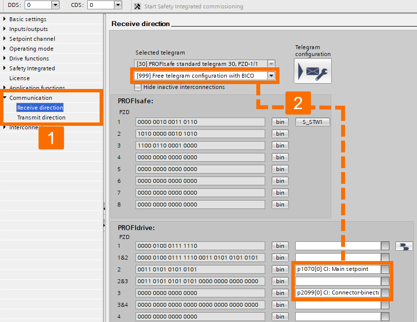
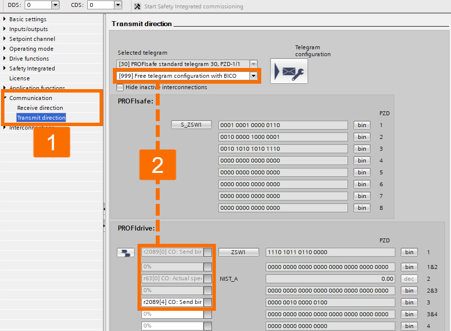
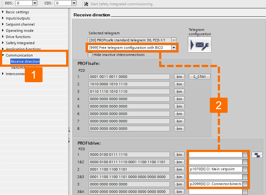
Configure the communication parameters for seamless interaction between devices.

Figure 3.19: Enhancing Siemens drive safety - Configuring G115D drive - Receiving data
Figure 3.20: Enhancing Siemens drive safety - Configuring G115D drive - Transmitting data

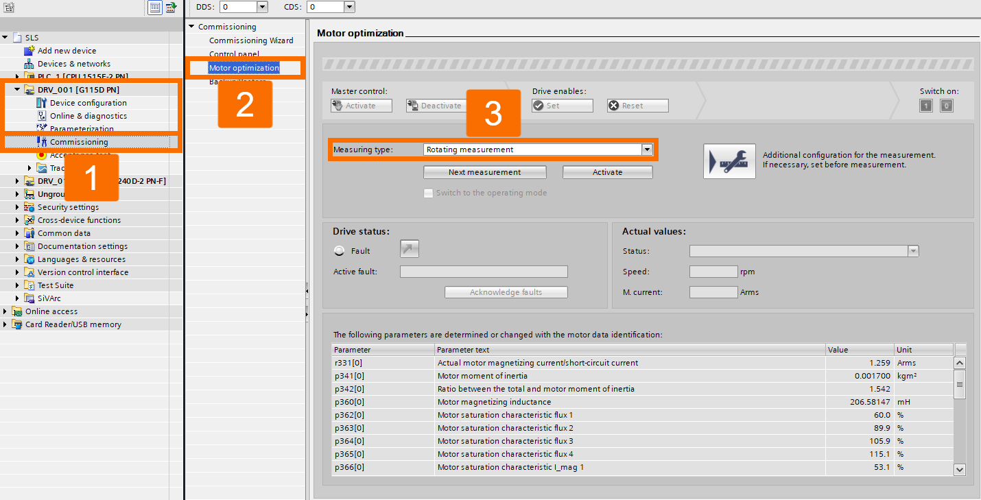
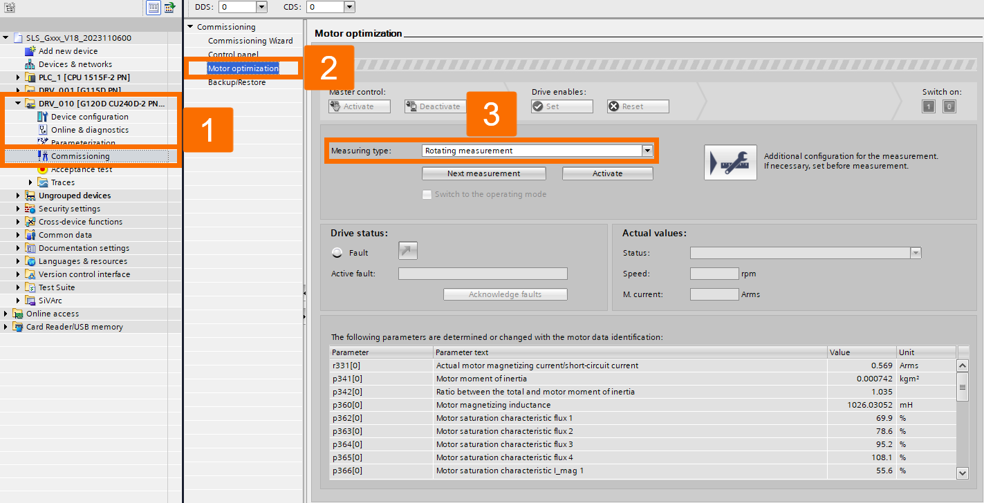
Initiate the process of optimizing the motor performance for the Siemens G115D drive. Before conducting motor optimization, it is essential to carry out safety commissioning procedures, which will be explained later in this tutorial.

Figure 3.21: Enhancing Siemens drive safety - Configuring G115D drive - Motor optimization

Begin the commissioning procedure for the Siemens G120D drive by following the commissioning wizard and completing all the necessary data fields.

Figure 3.22: Enhancing Siemens drive safety - Configuring G120D drive - Setpoint specification
Figure 3.23: Enhancing Siemens drive safety - Configuring G120D drive - Open-loop/Closed-loop control type
Figure 3.24: Enhancing Siemens drive safety - Configuring G120D drive - Defaults of the setpoints/command sources
Figure 3.25: Enhancing Siemens drive safety - Configuring G120D drive - Drive setting
Figure 3.26: Enhancing Siemens drive safety - Configuring G120D drive - Motor specification
Figure 3.27: Enhancing Siemens drive safety - Configuring G120D drive - Motor holding brake
Figure 3.28: Enhancing Siemens drive safety - Configuring G120D drive - Important parameters
Figure 3.29: Enhancing Siemens drive safety - Configuring G120D drive - Drive functions
Figure 3.30: Enhancing Siemens drive safety - Configuring G120D drive - Encoder selection

Commence the parameter setup for the G120D drive.

Figure 3.31: Enhancing Siemens drive safety - Configuring G120D drive - Digital outputs configuration

Move forward in the parametrization tree to perform additional drive settings.

Figure 3.32: Enhancing Siemens drive safety - Configuring G120D drive - Controlling brake
Figure 3.33: Enhancing Siemens drive safety - Configuring G120D drive - Flying restart

Configure the parametrization settings for the safety integrated feature. Parameter settings should be carried out offline to maintain PLC software consistency. In the presence of SBR, follow the brake ramp while the drive slows down.

Figure 3.34: Enhancing Siemens drive safety - Configuring G120D drive - Selecting safety functionality
Figure 3.35: Enhancing Siemens drive safety - Configuring G120D drive - Actual value sensing for safety integration
Figure 3.36: Enhancing Siemens drive safety - Configuring G120D drive - Control type/safety functions
Figure 3.37: Enhancing Siemens drive safety - Configuring G120D drive - SLS configuration

Configure the signal link from the PLC and define timing presets for the 'Test stop' functionality.

Figure 3.38: Enhancing Siemens drive safety - Configuring G120D drive - Test stop

If you decide to use PROFIsafe telegram 900 rather than PROFIsafe telegram 30, enable the system connection for the drive's safety inputs according to the requirements. In any other case, keep the safety inputs unconnected.

Figure 3.39: Enhancing Siemens drive safety - Configuring G120D drive - Routing configuration for fail-safe digital input

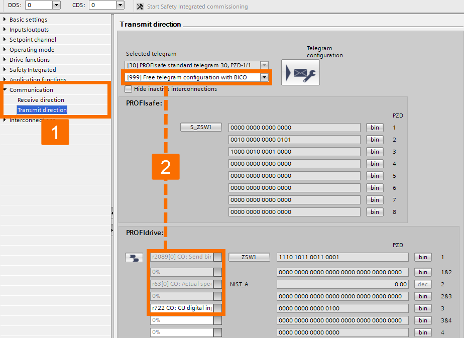
Configure the communication parametrization settings.

Figure 3.40: Enhancing Siemens drive safety - Configuring G120D drive - Receiving data
Figure 3.41: Enhancing Siemens drive safety - Configuring G120D drive - Transmitting data 

Begin optimizing the motor performance of the G120D drive.

Figure 3.42: Enhancing Siemens drive safety - Configuring G120D drive - Motor optimization

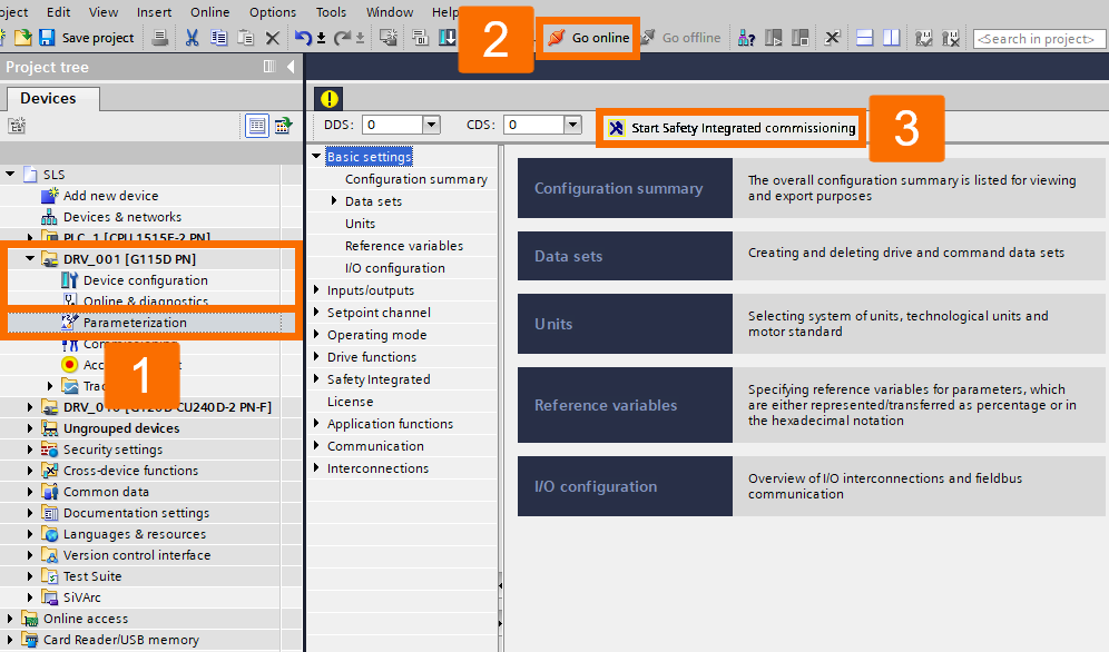
Upon finishing the offline hardware configuration, compiling and downloading the PLC software will become essential. Following that, ensure that the safety functions within the drives are activated in the online mode.

It is vital to proceed with the G115D drive safety commissioning to ensure the safety section of the PLC software remains consistent offline and online. The initial step involves updating the safety-related settings in the drive while it's online.

Figure 3.43: Enhancing Siemens drive safety - G115D drive safety commissioning

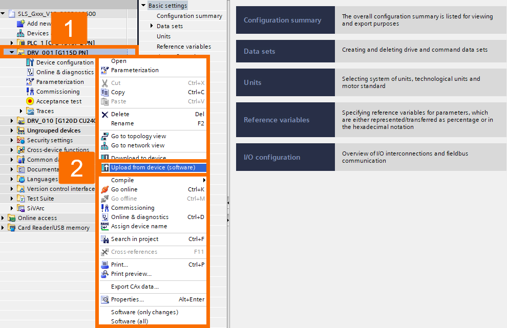
After successfully conducting the drive safety commissioning, transfer the updated checksum values from the drive back to the offline TIA project. If you skip the upload, when the offline drive parameters are downloaded again, it will overwrite the drive's safety settings with invalid safety data, necessitating a repetition of the safety commissioning process for the drive.

Figure 3.44: Enhancing Siemens drive safety - Uploading updated checksum values after safety commissioning from the G115D drive

To conduct the safety commissioning for the G120D drive, follow the same procedure as you did for the previous drive.

TIA Portal Project Overview

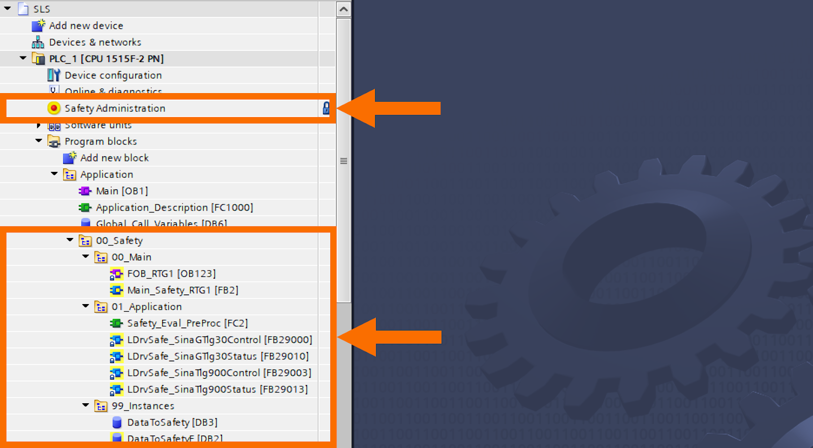
Within the TIA Portal application example project, you'll find two primary sections: safety and control.

Figure 4.1: Enhancing Siemens drive safety - TIA Portal project overview

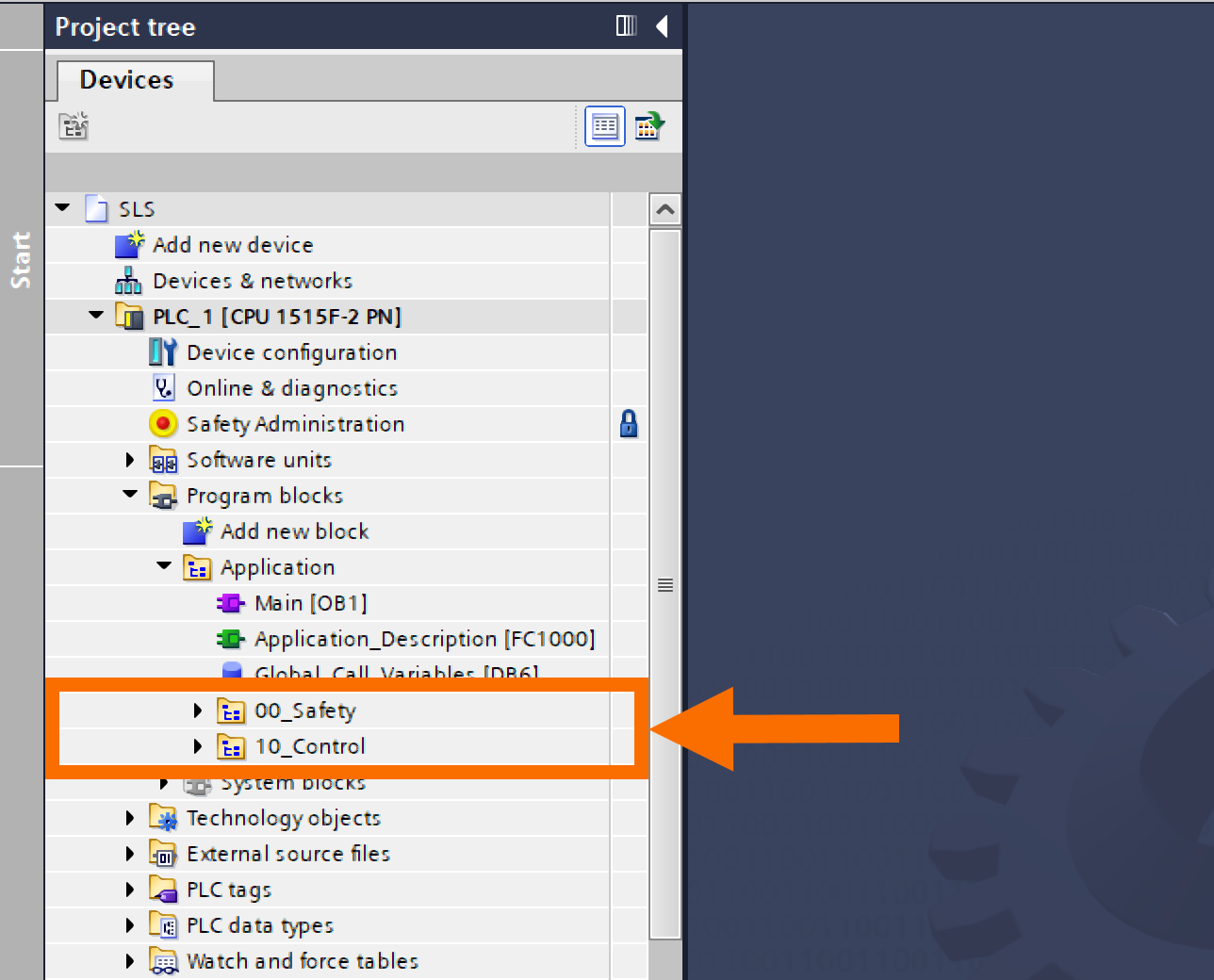
In the PLC software, the safety section is responsible for assessing and managing safety-related aspects such as safety administration (houses fundamental configurations of the safety task and is secured with a password for access control) and safety folder (consists of function blocks that are accompanied by their associated instant data blocks).

Figure 4.2: Enhancing Siemens drive safety - Safety section of the PLC software

Within the PLC software, the control part is dedicated to controlling and supervising the drives.

Figure 4.3: Enhancing Siemens drive safety - Control section of the PLC software

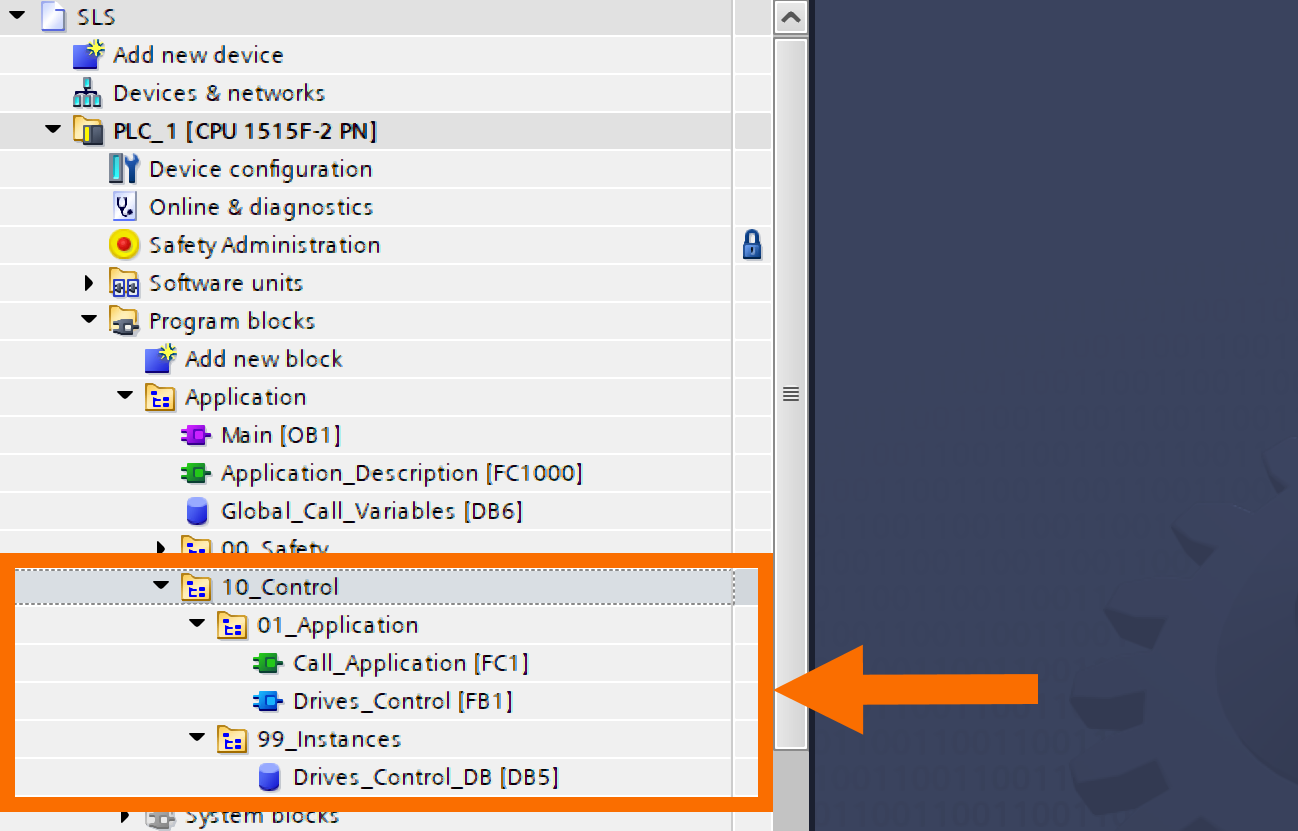
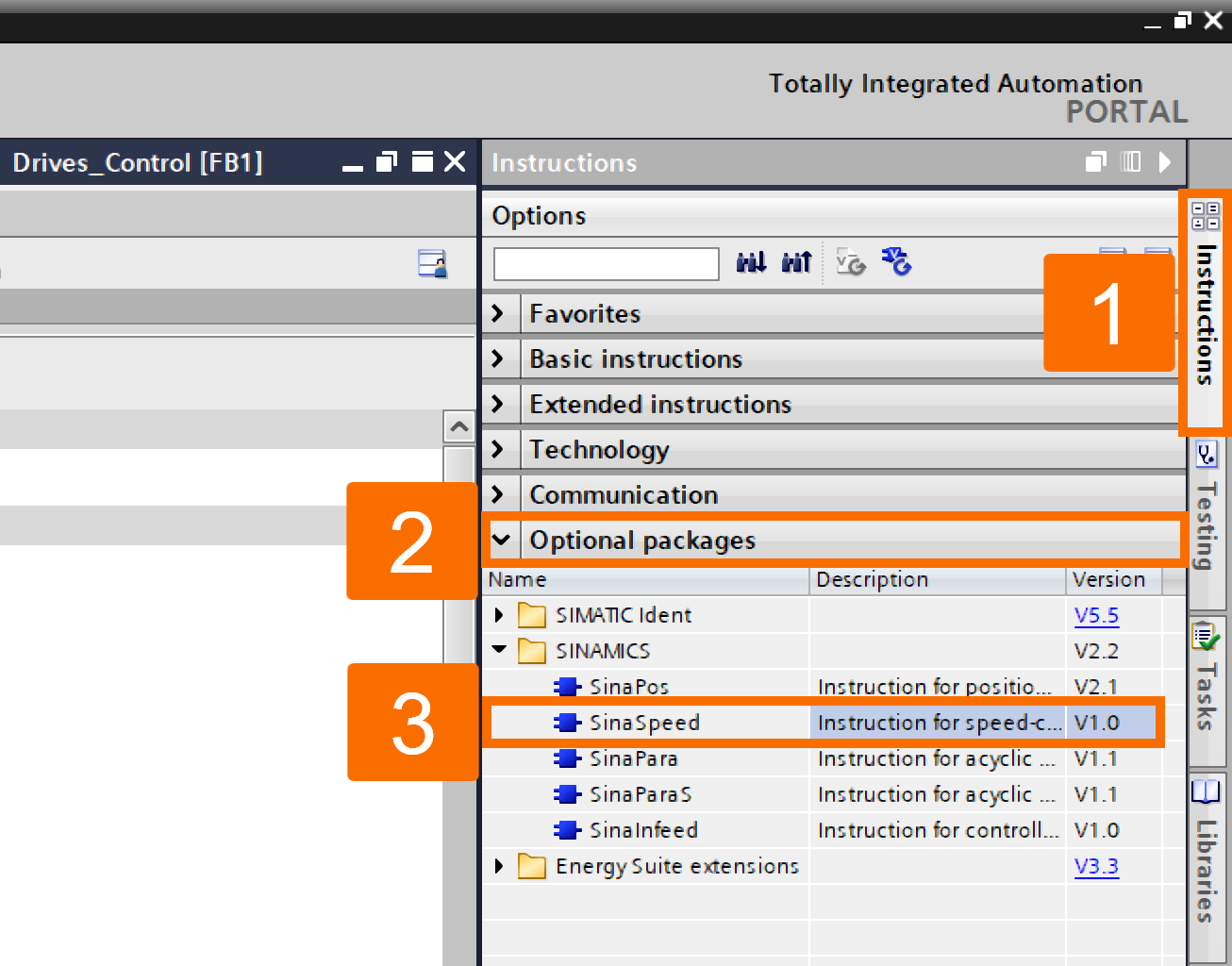
Control over the drives is achieved by implementing the SinaSpeed instruction.

Figure 4.4: Enhancing Siemens drive safety - Implementing SinaSpeed instruction for controlling the drive

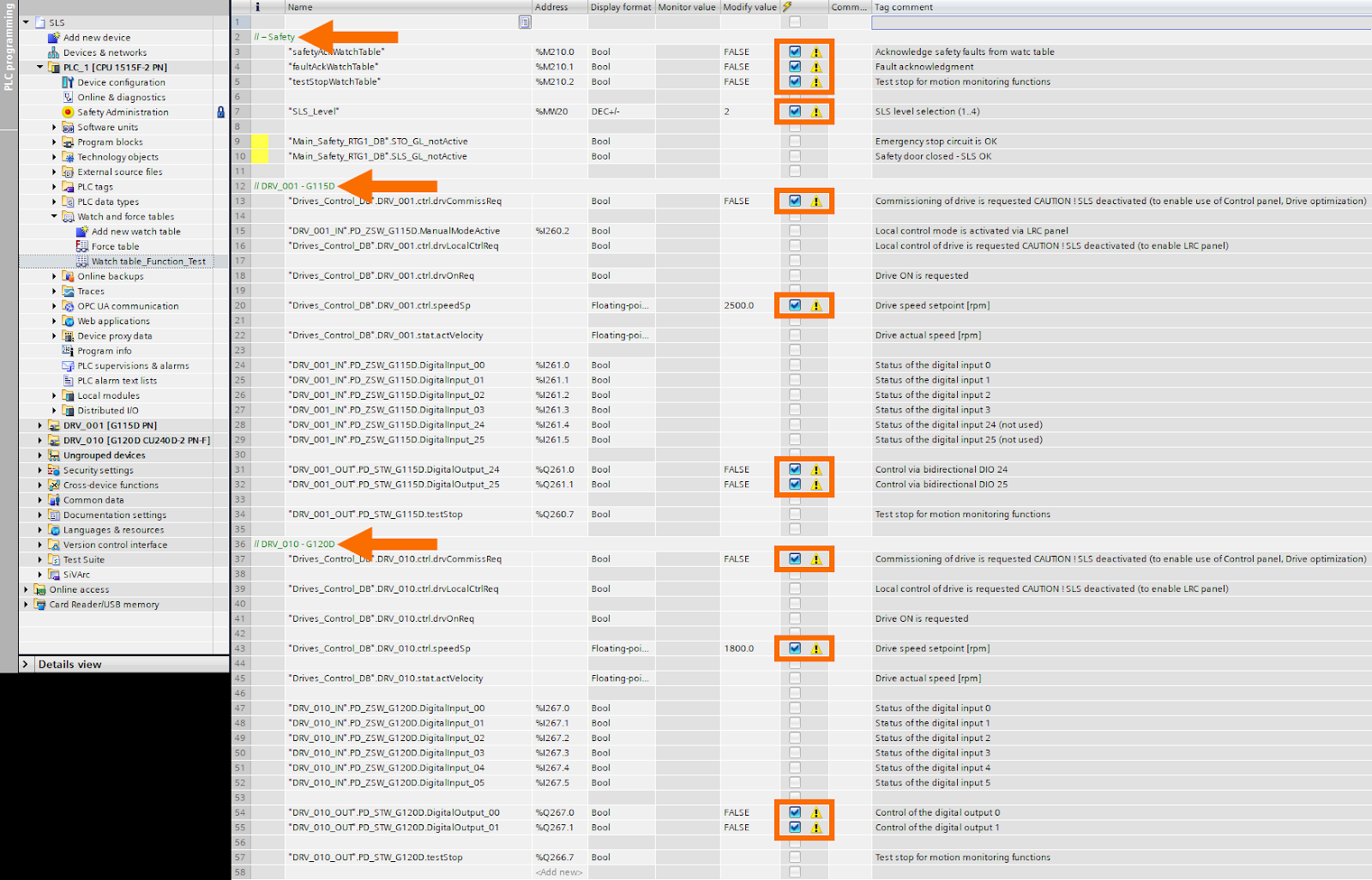
A collection of relevant tags is created to ensure the proper functioning of the safety functions and drive control. These tags can be monitored and adjusted using Watch and force tables. Tags designated as 'Modify value' play a role in controlling operations. The remaining tags serve the function of displaying the present status.

Figure 4.5: Enhancing Siemens drive safety - Monitoring relevant tags for proper functioning of the safety functions and drive control

Conclusion

In conclusion, you have been introduced to the application of the Safely Limited Speed (SLS) feature while operating Siemens distributed drives (SINAMICS G115D and G120D) through PROFINET. As part of your learning, you discovered that the Safely Limited Speed feature is essential for applications where the drive needs to keep running despite potential hazards.