Festo Servo Motor Tutorial - CMMT-ST-C8-1C-EP-S0 Festo Automation Suite Drive Software Installation

Introduction to Festo CMMT Drives
Festo is widely known for its pneumatic products. They’ve engineered, developed and produced top of the line solenoids, valves, actuators, pneumatic banks, and many other closely related devices that we see in every manufacturing plant. However, Festo has a lesser known lineup of products that extends beyond pneumatics. They provide means of control in the form of I/O blocks, motors, robotics, and other electrical devices.
In this article, we're going to go over the CMMT-ST Servo Drive which is ideal for high-efficiency tasks that have low power requirements. It’s small, easy to integrate into an existing system and provides an accurate control over the motor it’s paired with.
Downloading and Installing Festo Automation Suite and Components
Step 1 - Download and Install “Festo Automation Suite”
FAS is a tool used to configure, troubleshoot and work with Festo devices of various types. We’ll be using this software to configure our drive and motor. Furthermore, we will be using it to control and view the state of the motor at any given time.
The software is free.
To download, visit the following page.
In the search bar, look for “Festo Automation Suite” or “8084006” which is the part number for the software.
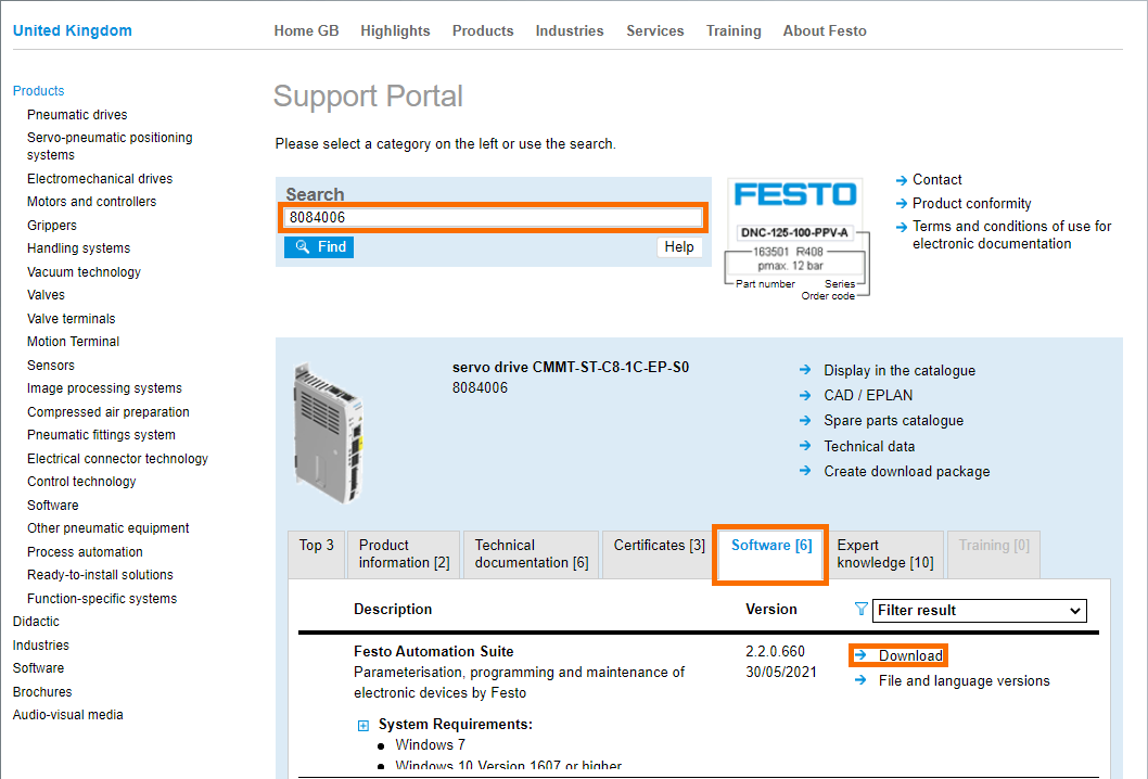
Note that the version of the software at the time of building this tutorial is 2.2.0.660. It’s possible that a different version will have a different interface than the one we will be showing here.
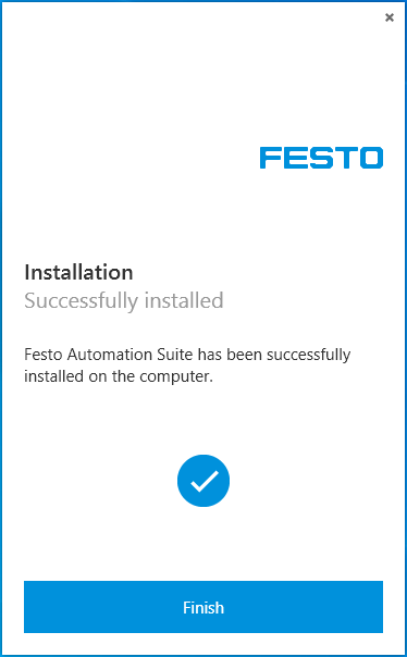
Once the file is downloaded, launch the tool and follow the on-screen instructions to install FAS onto your computer. We haven’t encountered any issues with the installation.
Step 2 - Download and Install “Festo Automation Suite Plug-In”
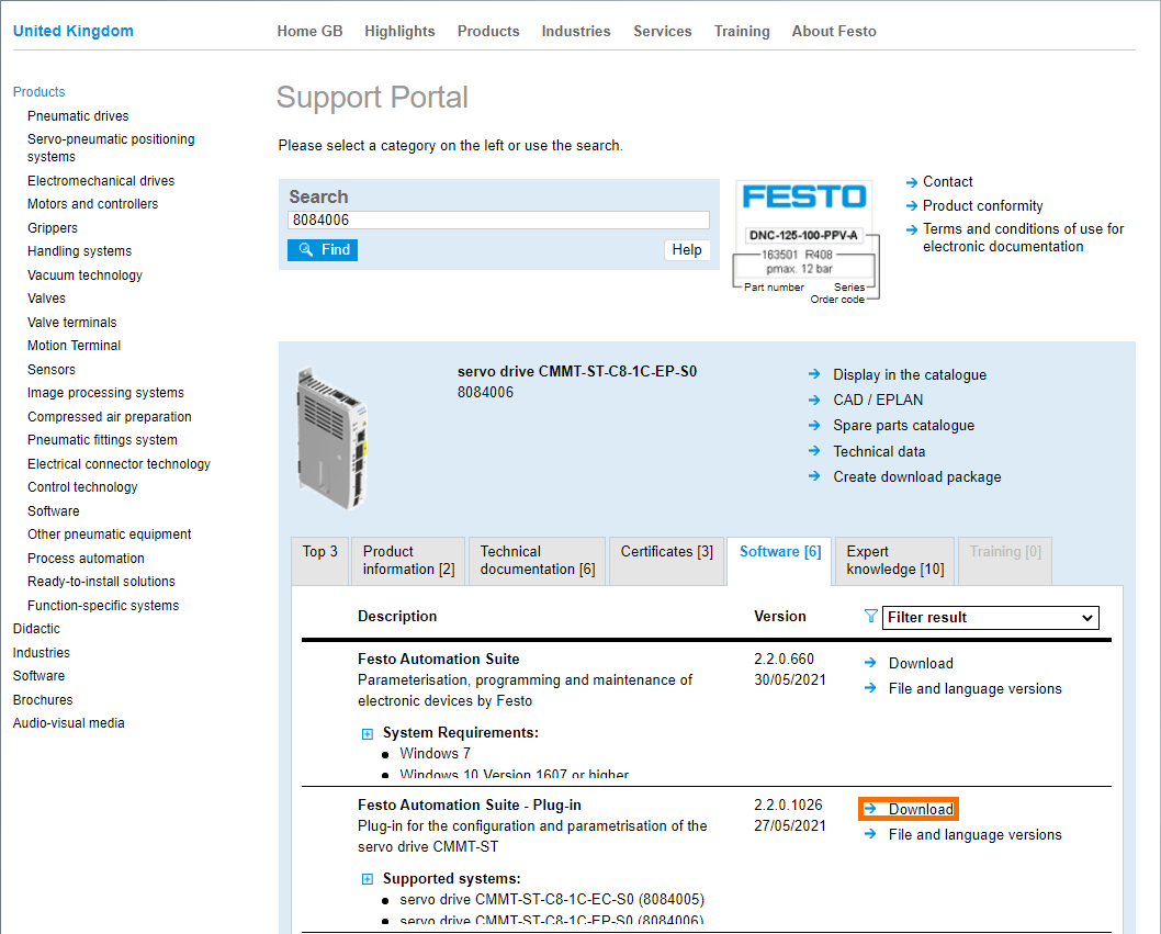
The Plug-In is specific to the device it’s tied to. In our case, we’re looking to interface with the CMMT-ST drive; we need to download the appropriate plugin from the same Support Portal.
Scroll down in the same menu as above and download the “Festo Automation Suite Plug-In”.
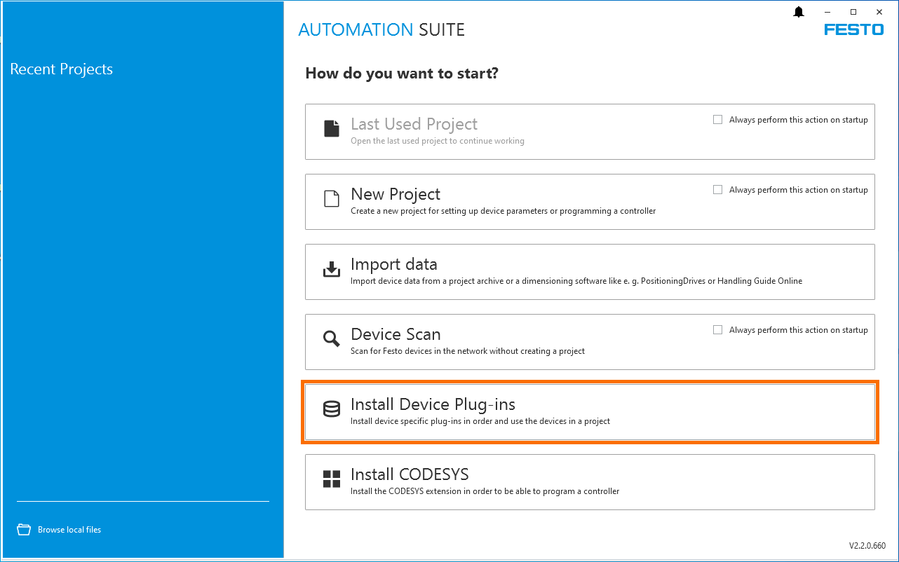
To install the plug-in, you’ll have to launch Festo Automation Suite and use the “Install Device Plug-ins” option to launch the file that has been downloaded.
Wiring the Hardware
The servo drive has two connections to the motor: power and encoder. The cables to connect both signals are included in the kit. The wiring diagrams shown below accurately represent the connections that need to be made on the drive and motor side. Note that the motor side cables are pre-wired into M12 and DB9 connectors.
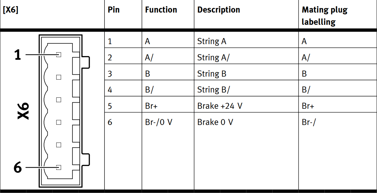
Here’s the wiring diagram for the power circuit on the X6 terminal:
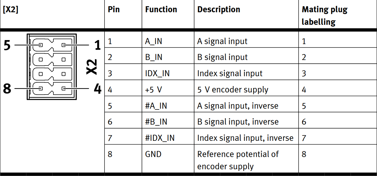
The wiring of the control circuit on the X2 terminal is as follows:
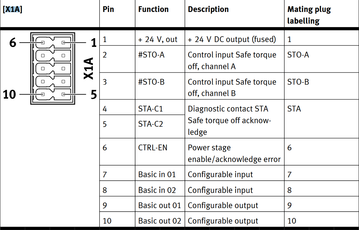
Lastly, we need to wire the X1A terminal that contains additional signals that impact the operation of the servo drive. Since we’re running the drive in a test environment, we’ve bypassed the safety by using a jumper between the Pin 1, Pin 2 and Pin 3 terminals. We’ve also wired the same 24VDC signal to Pin 6 that gives us control over software.
Configuring a New Festo Automation Suite Project
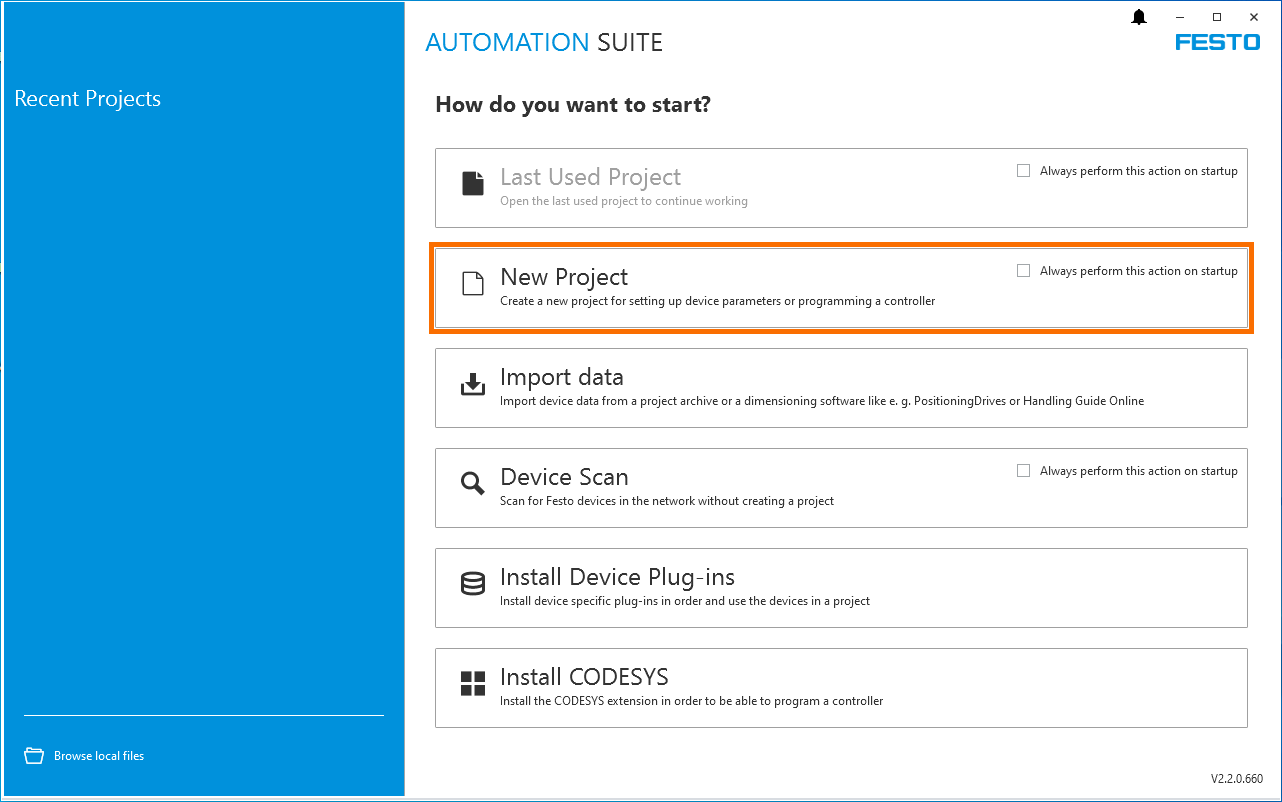
Now that we’ve installed the tools required, we can launch Festo Automation Suite and create a new project that will allow us to connect to the servo drive.
Select “New Project” from the main menu.
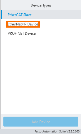
In order to set up the drive, we need to choose the appropriate device from the suite of drivers we installed.
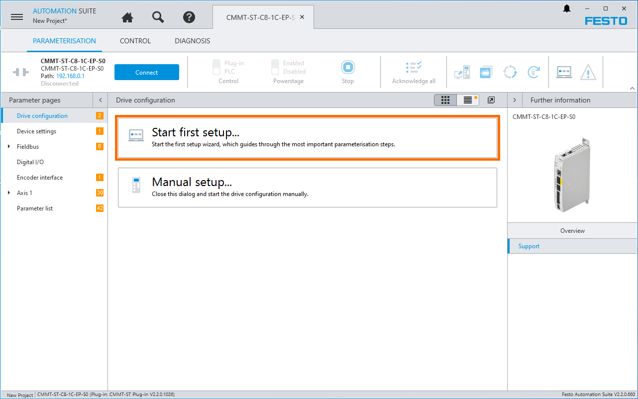
Once the device is added to the project, double-click the device to launch the plug-in configuration.
By using the “Start first step...” option, we can easily configure our drive for first-time use.
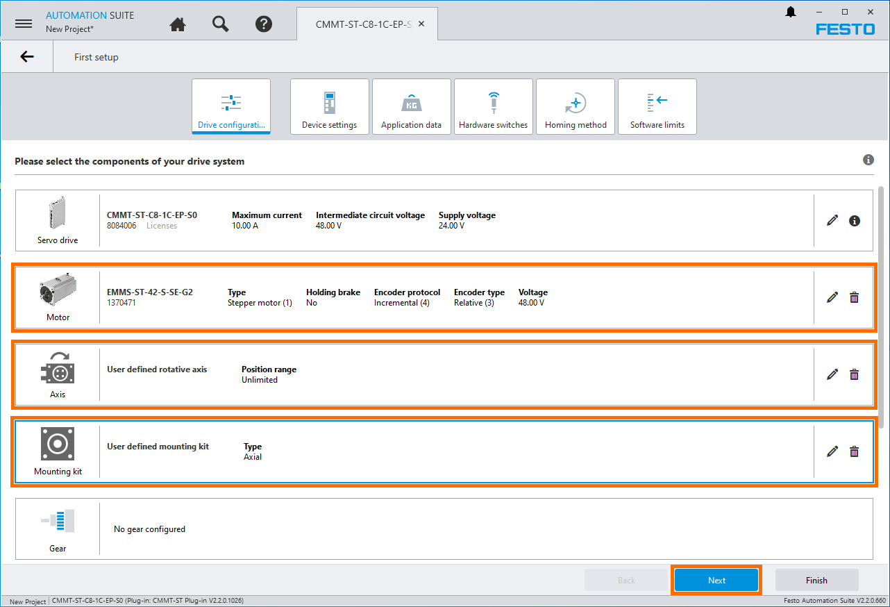
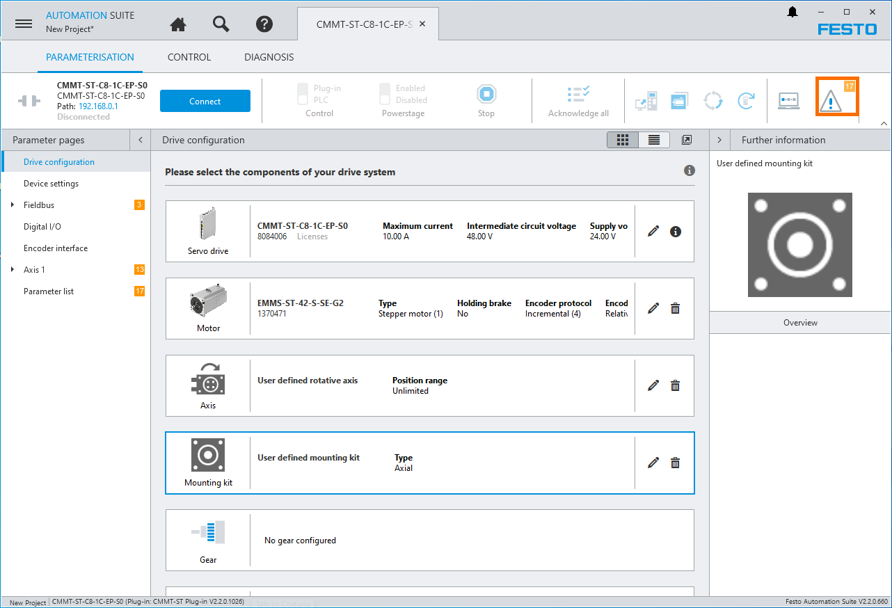
On the next page, we configure the drive, motor, axis and mounting kit. Note that the kit we’ve received from Festo does not contain hardware beyond the drive and the motor. Therefore, we’ve configured a virtual axis with an unlimited position and a “user defined” mounting kit.
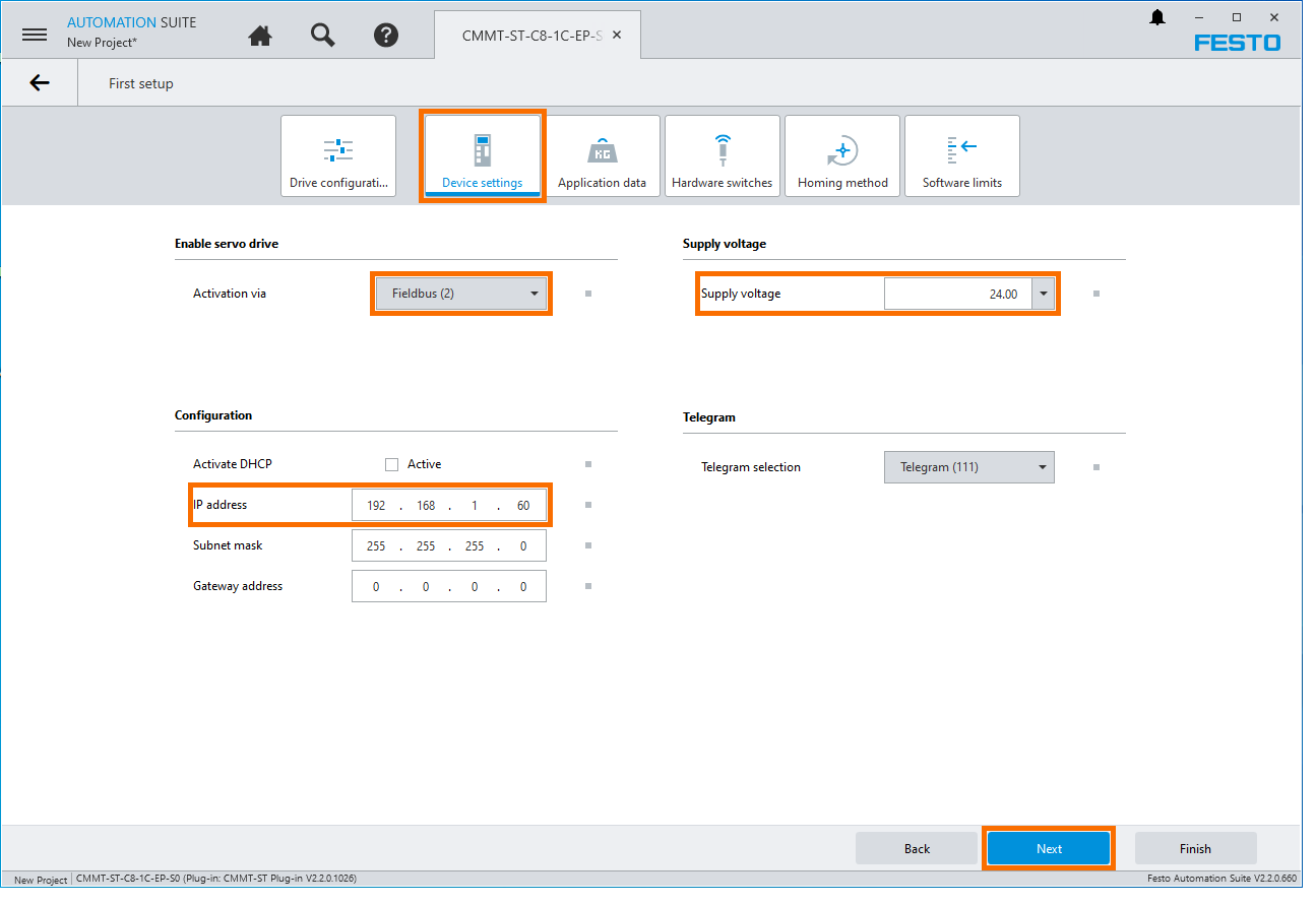
On the “Device Settings” page, we need to set the IP address of the drive, the “Activation” and the “Supply Voltage”
- IP address - The default IP of the servo drive is 192.168.0.1; in our case, we’ve changed the IP to 192.168.1.60
- Activation via - Fieldbus (2)
- Supply Voltage - As discussed previously, the drive was set to 24VDC on the input side.
Since the motor is not currently connected to a load, we’ll have to set the “Application moment of inertia” to 0.01. We recommend using the “autotune” features if a load is present.
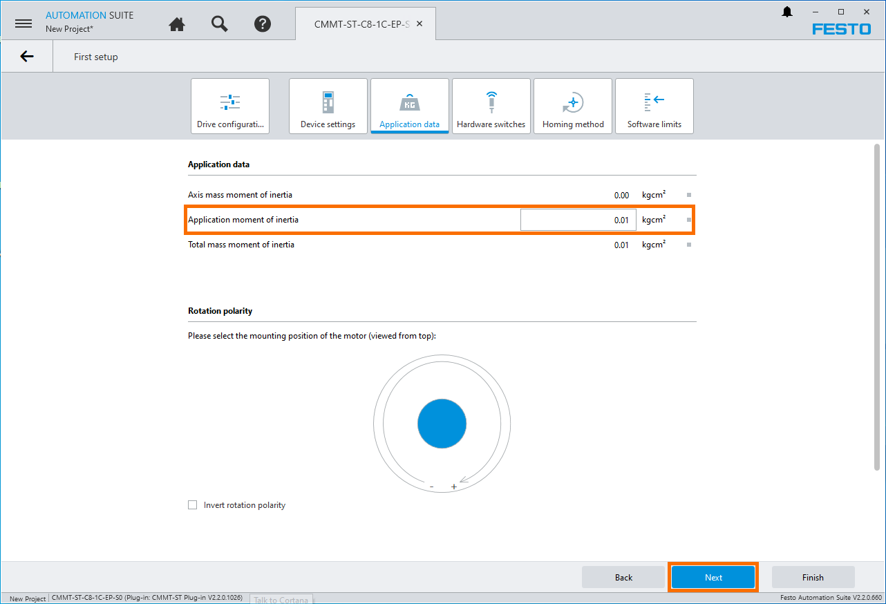
No other settings are changed. Press on Finish after reviewing the settings in other tabs in your application.
Connecting to the Servo Drive
Now that we’ve configured the project, we’re almost ready to connect. We need to resolve the “software” issues indicated by the Festo Automation Suite. To do so, we can press the “!” icon and “Apply” to set the values to the recommended parameters.
Connect an EtherNet cable (RJ45) from the computer to the drive front port. It’s important to note that although we set the IP of the drive to 192.168.1.60, the front port remains at the IP address of 192.168.0.1. Set your computer IP address to match the network (Ex: 192.168.0.100 / Subnet Mask 255.255.255.0)
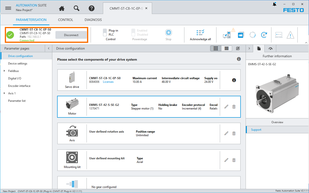
Press “Connect”.
If everything is configured as expected and the software connects to the drive, you should see the following at the top left of FAS:
Controlling the Servo Motor
At this point, we’ve connected to the drive and are able to issue commands to the motor.
Step 1 - Enable “Plug-in PLC Control”.
Step 2 - Enable “Powerstage”
Step 3 - Navigate to the “CONTROL” tab to issue commands.
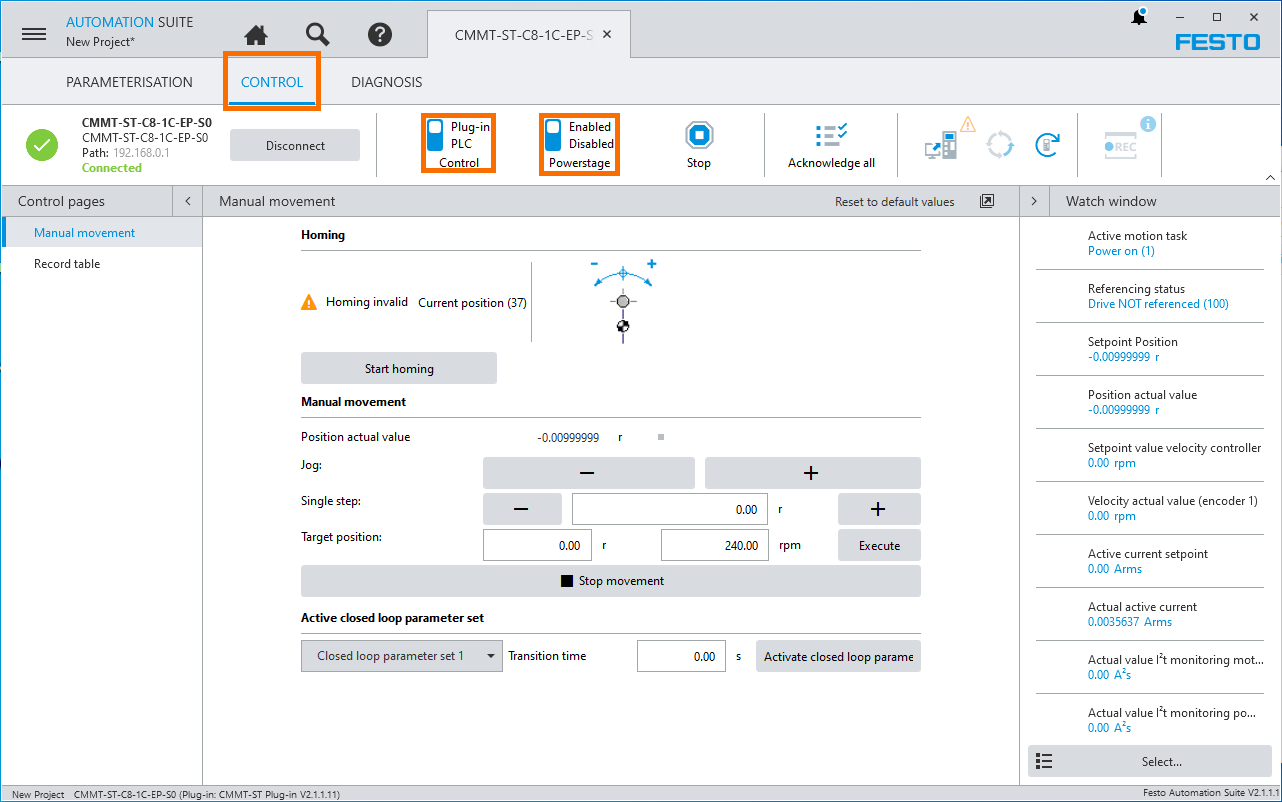
From the CONTROL screen, we may issue commands to move the motor to a desired position, jog it at a specified speed and home to the initial position.
Conclusion on Festo CMMT-ST Servo Drive
In this tutorial we’ve covered the installation of the Festo Automation Suite, the Plug-In driver and the hardware / software configuration of the first project. We’ve connected to the drive and executed basic motion commands.
In the following tutorial, we’re going to connect this servo motor into an Allen Bradley CompactLogix PLC and execute some of the commands remotely.
