Introduction to Function Block Programming in RSLogix 5000

Introduction to Function Block Programming
One of the most commonly used PLC programming languages is Function Block Diagram, or FBD. Although this language is rarely used for an entire system, it makes a lot of sense in areas where a continuous process flow is taking place or if there’s a need for complex instruction sequences that may be laid out much easier in function blocks over ladder logic; we will see an example of such implementations in this tutorial.
Function Block Programming is a language outlined in the IEC 61131-3 standard. It is a visual programming language that ties various instruction blocks together and allows them to execute a process based on conditional logic.
The advantages of function block diagrams are that they’re very easy to follow and understand. They are generally laid out to mimic a specific process thus making it easy to understand for those who don’t have a background in plc programming.
The goal of this tutorial is to introduce you to Function Block Diagram Programming in RSLogix 5000 and provide several application examples that illustrate the purpose of the language. Finally, we will walk through the process of creating a small function block diagram application and explain the choices behind the instructions used.
What is a Function Block Diagram?
In chemical and process engineering, the flow of a production flow is generally established in blocks that represent different areas of the process. Such a diagram allows engineers to glance over the process and understand which inputs are sent into the system, the transformations that take place and the outputs coming out of the system.
In a fashion similar to the chemical process flow diagrams, function block diagrams in PLC programming allow users to create a system that takes multiple inputs, sends them through various instruction blocks and changes specified outputs.
As mentioned above, it’s difficult to create an entire process in function block diagrams as the layout becomes complex and challenging to manage. Therefore, this language is most often paired with ladder logic or structured text.
Prerequisites
- This tutorial assumes no prior knowledge of function blocks. However, we will be covering most instruction blocks in a shorter time than we did in most ladder logic instructions. For the most part, these work exactly the same way as their ladder logic counterparts; please refer to the materials on ladder logic.
- Basic Ladder Logic Understanding
- Studio 5000 v30.11
- CompactLogix PLC - 1769-L24ER-QB1B
Function Block Diagram Fundamentals
Let’s look at a basic example of a function block to understand the basics of the language. An ADD PLC programming instruction will take two operands, add them and store the result in the output register. As a reminder, here’s an example of the ADD Instruction programmed in ladder logic:
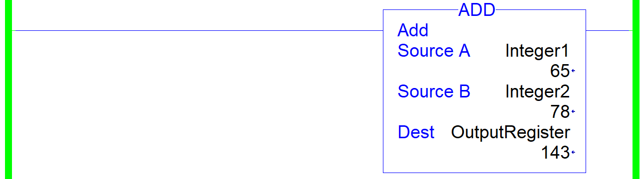
The ADD instruction will take the value of “Integer1”, add it to the “Integer2” and store the result (143) in the “OutputRegister”. The same can be expected in the Function Block Diagram of this instruction. However, the layout is different. Here’s the same instruction implemented in FBD:
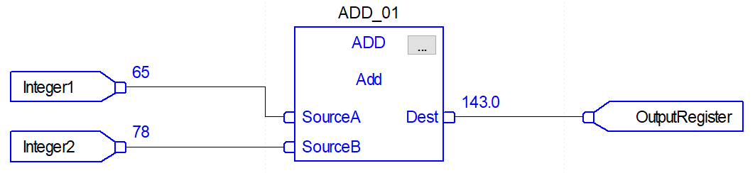
Although the outcome is identical, FBD programming requires additional components to work.
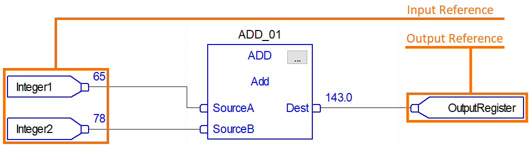
The ADD block will not allow the user to enter registers that will be tied to the inputs or outputs. Additional structures, called input reference and output reference, must be added to the implementation. These structures can reference and integer and in other cases a boolean or other types of tags just as you would expect in ladder logic. By drawing connections from the references to the function block, the user will specify which references must be used by the ADD block computation.
As we expand the use of function blocks, we may create a slightly more complex combination of instructions as displayed in the diagram below.
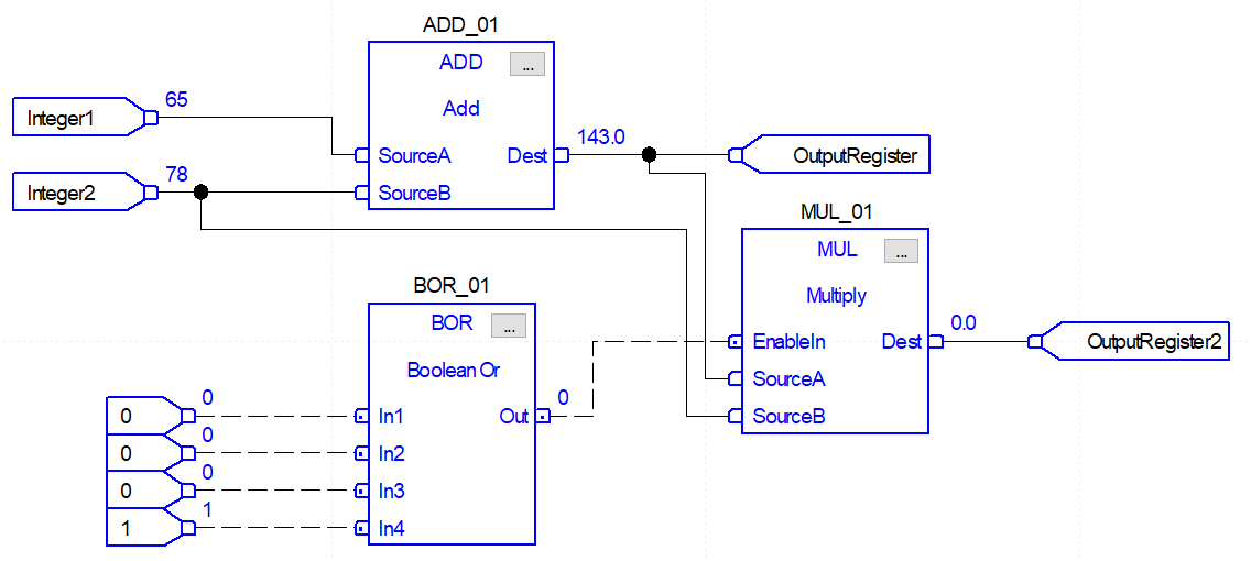
In the diagram above, we’re looking at the same ADD block. However, we now have two additional blocks: BOR and MUL. Furthermore, we may also notice two tri-connections tied to the “Integer2” and “OutputRegister”. In Function Block Diagrams, the user is able to route the values of registers to multiple destinations.
Note: it’s not possible to route two input registers to a single instruction block input. However, it is possible to route a single output to two different inputs.
The BOR Instruction represents a “Boolean OR” logic operation. This function is taken from logic gate functions and evaluates to true whenever any of the inputs is equal to 1 or logic HIGH.
Note: the connections to and from the BOR function block are dotted while the ones on the other blocks are solid. Furthermore, there is a dot in every input and output of that block as well as the “EnableIN” input of the MUL block. This is done on purpose; these connections represent booleans while the solid lines represent integers. RSLogix and Studio 5000 will prevent the user to route incorrect data types into and out of instructions.
Custom Function Block Diagram Instructions
As mentioned above, most instructions that you’ll see in ladder logic will also be available in function block diagrams. In addition to standard Allen Bradley blocks, the user may choose to create their own code encapsulations that will be then used in FBDs. This practice is utilized whenever an application requires the use of similar elements and the implementation of a custom function block would save time during the programming and commissioning phase. Furthermore, this allows the programmer to standardize the function and push a single update to all instances of the same function block implementation.
Function Block Diagram Programming Instructions
In ladder logic, we had a distinction between the conditional and executional blocks. In simple terms, the conditions, located on the left side of a rung, needed to be true in order for the executional blocks to make changes specified within them. In function block diagrams, this paradigm is non-obvious as the user can create complex layouts and the blocks become intertwined. However, blocks can still be thought of as conditional or executonal. In the diagram above, the BOR instruction was used to evaluate the state of four inputs, while the MUL instruction was used to change the output register based on the values of the inputs.
Logical Bit Manipulation Instructions
Boolean bit manipulation involves verifying the conditions of input bits and setting an output based on the logic defined by the instruction. This action is performed through XIC, XIO Instructions paired with rung branches. In function block diagrams, this requires the use of BAND, BOR, BXOR and BNOT instructions. Let’s explore each one in detail and discuss potential applications of each one.
Technical Note - FBD Advanced Settings in RSLogix 5000
Every function block diagram instruction has a set of parameters that may change the layout of the instruction, add and/or subtract certain functionalities.
To access the settings menu of a function block in RSLogix 5000, click the “...” box in the top left corner of the function.
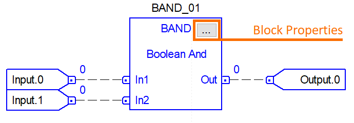
Once open, the user will be presented with a list of settings, their description, as well as an ability to toggle the setting on/off or to set it to a specific value. Note that the plc programmer is able to view, but not edit the settings in run mode. The sheet must be placed in edit mode in order to allow for changes.
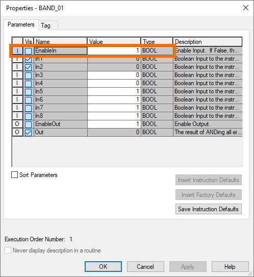
The above screenshot is showing a settings menu for the BAND instruction shown above. The “EnableIn” input is selected to show a “hidden” by default setting that may be used to enable or disable the instruction based on a certain tag value. In other words, if the “vis” box is checked for the “EnableIn” row, the “EnableIn” bit will appear on the instruction and allow a dynamic tie-in of a boolean. By default, this value is set to 1 to always execute the instruction.
BAND Function Block Diagram Instruction
The BAND Instruction takes a fixed number of inputs, processes them all through the boolean AND operator and sets the output bit to 0 or 1 depending on the state of the inputs.
The AND operator is commonly used in boolean logic, computer comparators and electronic circuits.
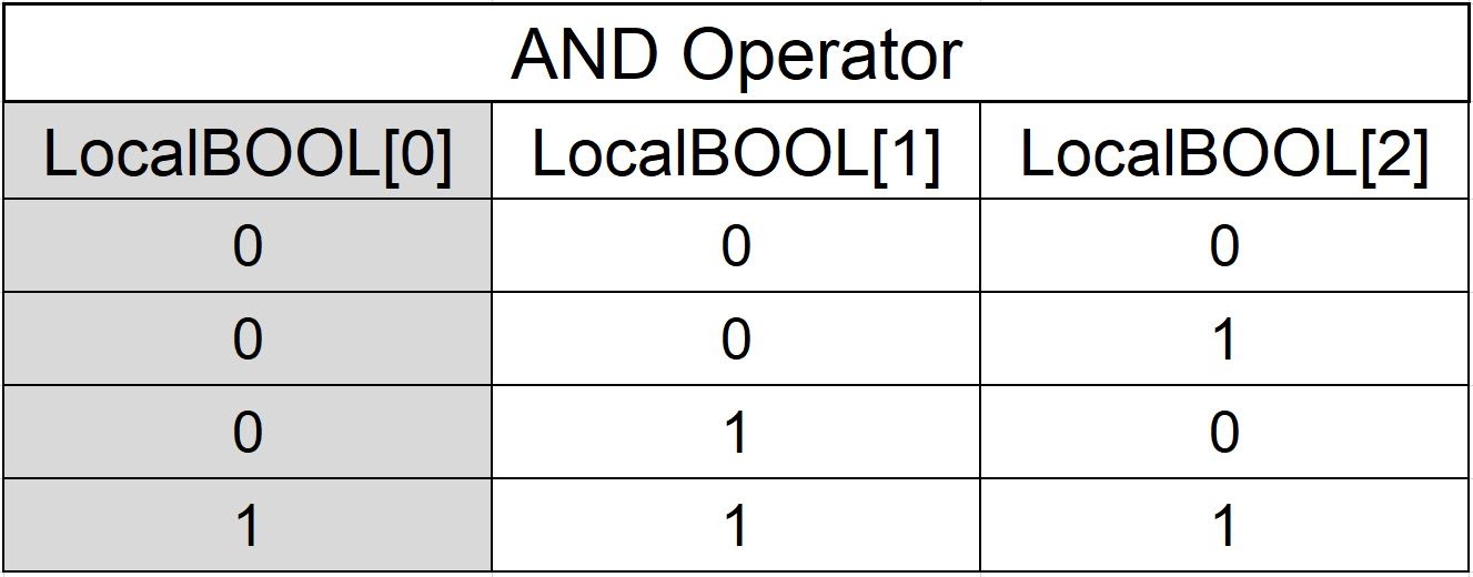
The BAND instruction is configurable to accept from one to eight (8) inputs that will be processed into a single output bit. The table below outlines the outcome of two inputs (LocalBOOL[1] and LocalBOOL[2]) processed into the output of LocalBOOL[0]
The Instruction will behave in exactly the same manner. It will take the two inputs and process them into the output per the logic outlined above. Here are the four states of the inputs and corresponding output.
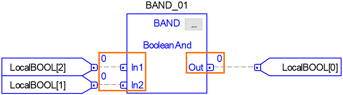
Important Note: As mentioned above, the instruction settings may be accessed and set the BAND to accept up to 8 different inputs. Doing so allows the user to use one instruction to evaluate multiple inputs at once. If there’s a need to evaluate additional inputs, multiple instructions may be chained together.
Common Use Case of the BAND Instruction
A BAND operator may be used to check for certain start conditions of a piece of equipment. Imagine that a case packer has multiple doors with safety switches on them. Although a safety rated circuit is needed to latch in a relay, the PLC programmer will utilize the BAND to make sure that all the doors have been closed before setting a “Ready_To_Run” bit. In other words, the front safety door AND the rear safety door AND the drive safeties AND other conditions must be met before allowing the machine to run. Once that bit is set, the operator may issue a Start command via a push-button or HMI.
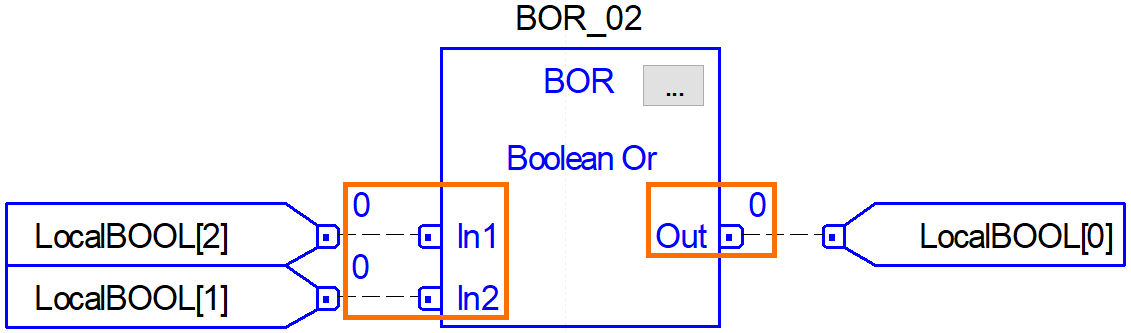
BOR Function Block Diagram Instruction
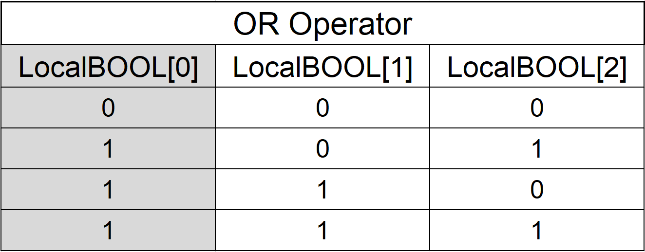
The BOR, or Boolean Or, instruction serves a similar purpose as the BAND instruction. However, the BOR will evaluate the inputs based on the logical OR operator. In this case, if any of the inputs are set to a logic “1”, the output will be set to “1”. Here’s a truth table that is used to evaluate the state of the output:
The BOR Instruction will take the same number of inputs as the BAND. Here’s the implementation in Function Block Diagrams in RSLogix 5000.
Common Use Case of the BOR Instruction
The BOR Instruction is used in cases where any active input needs to trigger a condition. Let’s look at the same application as above: the case packer. A case packer is placed in “Run” mode and is packing cases. While it’s making a case, a fault occurs. The expected action is for the machine to stop. In this case, the logic to be expected is that the routine will monitor ANY fault to occur. If a door is opened OR if the box is missing OR if the pressure is low OR any other abnormal condition occurs, the machine is faulted, stopped and the appropriate alarm is displayed.
BXOR Function Block Diagram Instruction
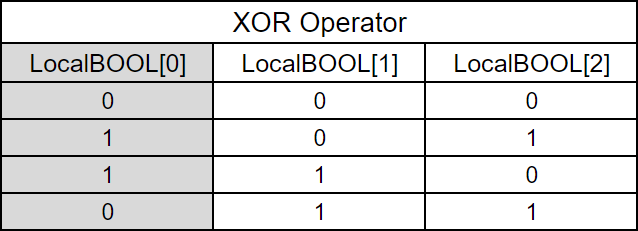
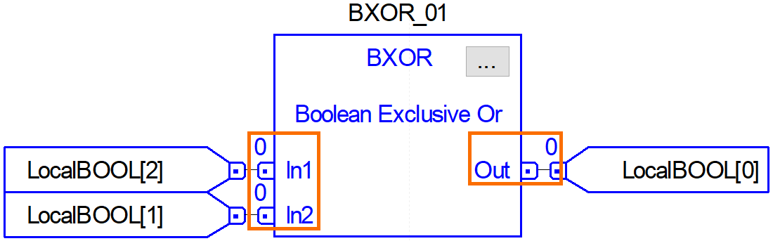
The BXOR, or the Boolean Exclusive Or Instruction, will take two inputs and set an output based on a set of conditions. This logical instruction will evaluate to TRUE when the inputs are of separate values. In other words, you can expect the following operation, or truth table, from this instruction:
It’s important to note that unlike the previous instructions, the XOR instruction will take a maximum of two inputs. The reason for that is the underlying condition of this instruction: return a true whenever two inputs are of different values. Common sense would suggest that no matter what you set three or more inputs to, there’s always going to be the same value in binary. In other words, you may only compare two inputs using this instruction. Here’s what the settings menu looks like:
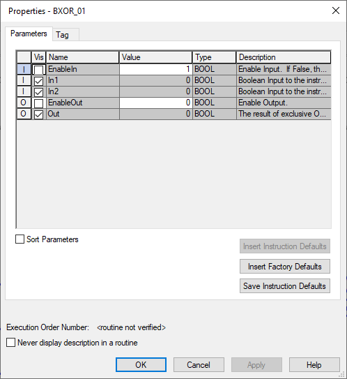
Here’s the implementation of this instruction in Studio 5000 as well as the response of the output based on the changes in the input values:
Common Use Case of the BXOR Instruction
Per the truth table above, the BXOR will give the PLC programmer information when an input is active while another isn’t. This is important in applications that rely on differential feedback. For example, consider a process valve with sensors that read an open and closed position. When the valve is in the OPEN position, Sensor 1 should read “HIGH” and Sensor 2 should read “LOW”. In the opposite setpoint, Sensor 1 should read “”LOW” while sensor 2 should read “HIGH”. In the case that the sensors are both reading “HIGH” or “LOW”, the valve is in an unknown, faulted state. The BXOR instruction can be used to detect such a state and issue an alarm.
Note: In the application above, a PLC programmer would utilize a TON Timer to make sure that the valve has been given enough time to transition between the two states. Otherwise, the plc program may fault immediately during the transition.
BNOT Function Block Diagram Instruction
The BNOT function block diagram instruction will take an input and change it to the opposite value. If the input is “HIGH”, the output will be set to “LOW”. Similarly, if the input is “LOW”, the output will be set to “HIGH”.
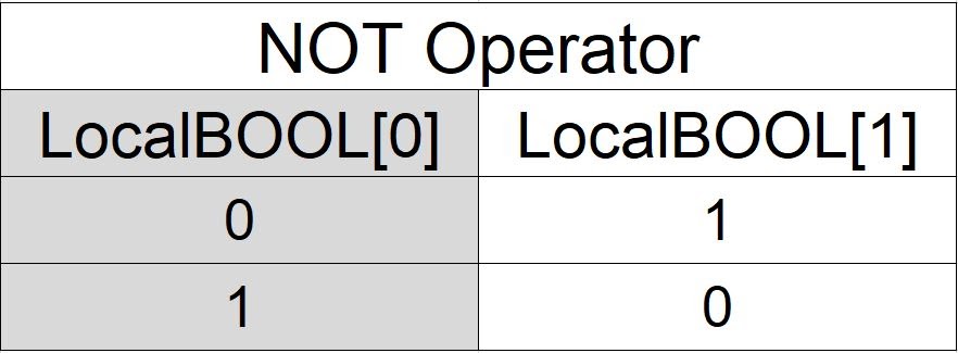
In Studio 5000, the instruction can be implemented as such:
Common Use Case of the BNOT Instruction
The BNOT Instruction can be implemented in ladder logic through the use of an XIO and OTE rung. By evaluating the status of a certain bit and setting it to the opposite, the programmer may create a scenario of dual conditions. For example, when the “MachineRunning” bit is set to 1, the machine is actually running. The PLC programmer may choose to continuously utilize an XIO of the MachineRunning bit to verify that it is NOT Running. However, this isn’t possible in function blocks diagram programming. The programmer will have to create a BNOT instruction and set a “MachineStopped” tag to the opposite value of the MachineRunning.
Mathematical Function Block Diagram Instructions
In Function Block Diagram programming, it’s very easy to implement mathematical instructions without the need of a transitional register. In other words, most of the analog scaling, complex mathematical calculations and process validations should be done in function block diagrams.
In ladder logic, the PLC programmer that needs to multiply two values and subtract the result from another value would have to create two steps and a register that would save this value. In function block diagrams, one can implement the following diagram to calculate the temperature conversion between Farhenheit and Celcius:
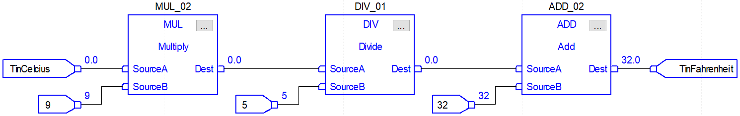
Notice that the chain of function blog diagrams is able to operate without the need to store the output values of each block. The programmer can chain these blocks one after the other and tie the outputs to the following block. Through the same operation, the programmer may choose to send the values in Celsius as well as Farhenheit to an HMI. In function block diagrams, one can do this by drawing connections to appropriate blocks. Here’s a modified diagram of the instruction above:
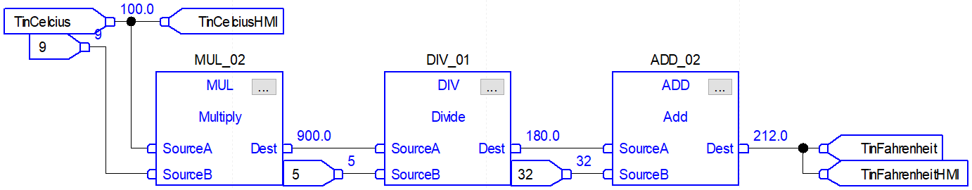
In this case, the assignment is made to the HMI tags simultaneously as the registers are used in the function block instructions. Function Block diagrams are also rearranged to demonstrate a high flexibility in the layout of the instructions. The programmer can choose how to build the diagram, position the instruction blocks and tie the tags back to where they are used.
Conclusion
In this article, we went over function block diagram PLC programming, some of the instructions as well as the configurations and particularities in RSLogix and Studio 5000. FBD programming is very popular in process programming which follows a natural layout of the physical instrumentation. Furthermore, FBD greatly simplifies the visualization of how tags are used, transformed and sent between systems.
By learning how function block diagrams are built, a skilled programmer may leverage them in particular situations that may not be as easy to implement in ladder logic or structured text programming.
