Generating Analog Output Signal for Fail-Safe System in Siemens TIA Portal

Introduction
This tutorial example shows how to implement a fail-safe analog value output for current up to SIL 3 and voltage up to SIL 2.
The implementation uses a standard ET 200SP analog card. It is under the constant supervision of a fail-safe analog input card and is terminated by a fail-safe output card.
The usual instances where this is applied include flow regulation valves, stepper motors, and speed of soft starters, all with fail-safe control.
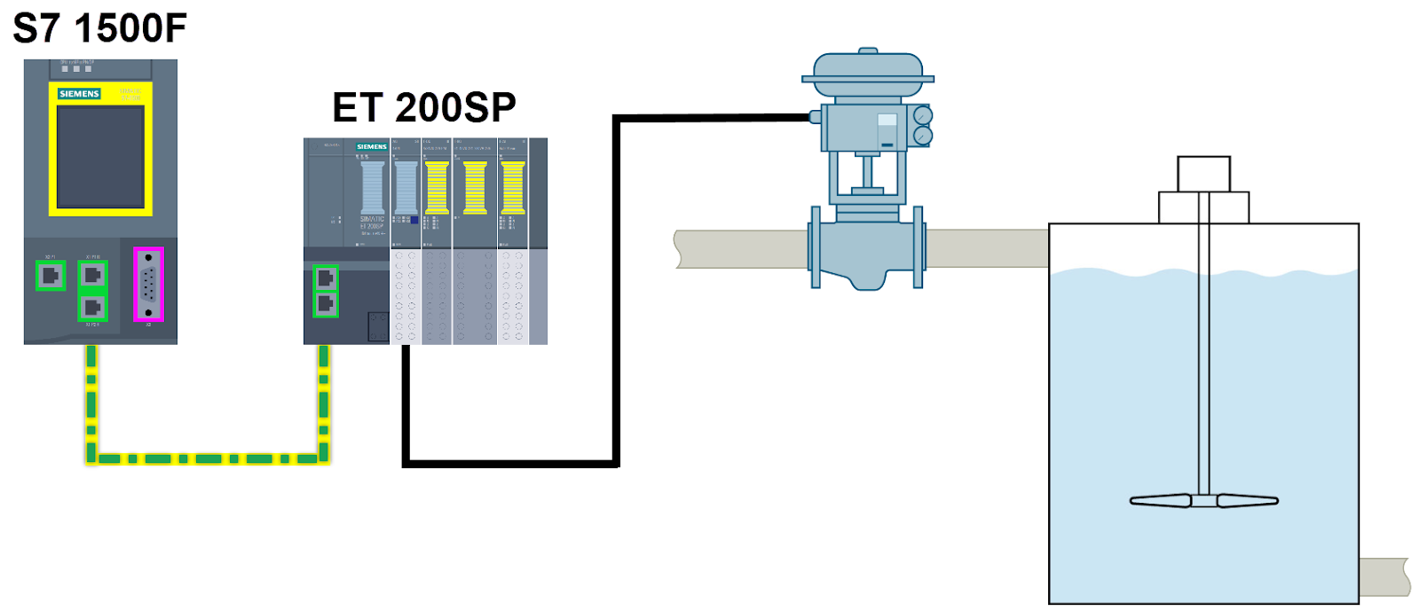
This example stands out due to its ability to integrate seamlessly into an already established system. The system includes a fail-safe S7 PLC and ET 200SP, operating within the Safety Advanced environment of Siemens TIA Portal. A schematic overview of the application area is illustrated in Figure 1.1.
Prerequisites
What you will need to follow along with this tutorial:
- The TIA Portal software should be installed on your computer. While version 18 is used in this tutorial, other versions of the TIA Portal are also compatible.
- Understanding the concepts of safety in automation systems.
Operation Principle
This practical example relies on combining standard cards alongside mechanisms of plausibility checking within the fail-safe program section.
For this purpose, the FAnalogOut function block was specially developed. Possible analog value options are 0 to 20 mA, 4 to 20 mA, and 0 to 10 V.
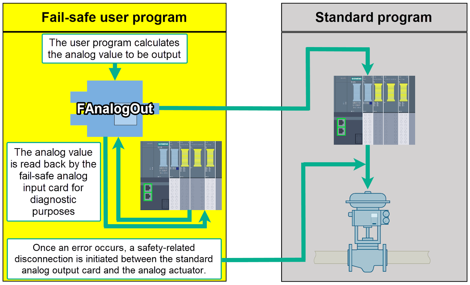
The sequence of functions for the function block is shown in Figure 2.1. Within the fail-safe user program, the block is executed each cycle to check the actual value of the analog output card and setpoint.
Hardware Configuration
The components used in this practical example are as follows:
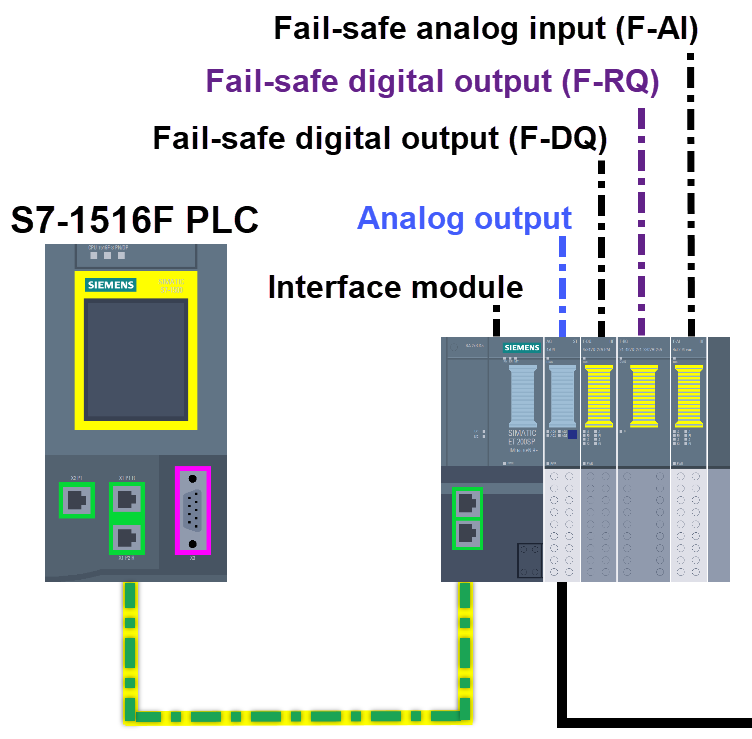
- CPU 1516F-3 PN/DP
- ET 200SP: including an interface module, analog output (AQ ST), fail-safe digital outputs (F-DQ 24VDC and F-RQ), and fail-safe analog input (F-AI).
Wiring
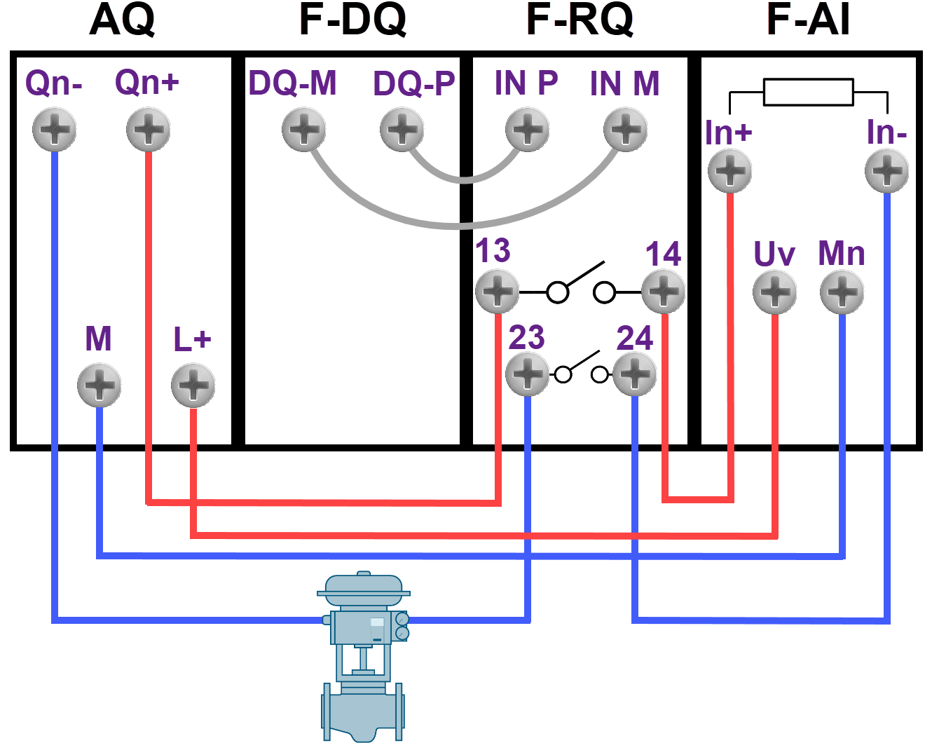
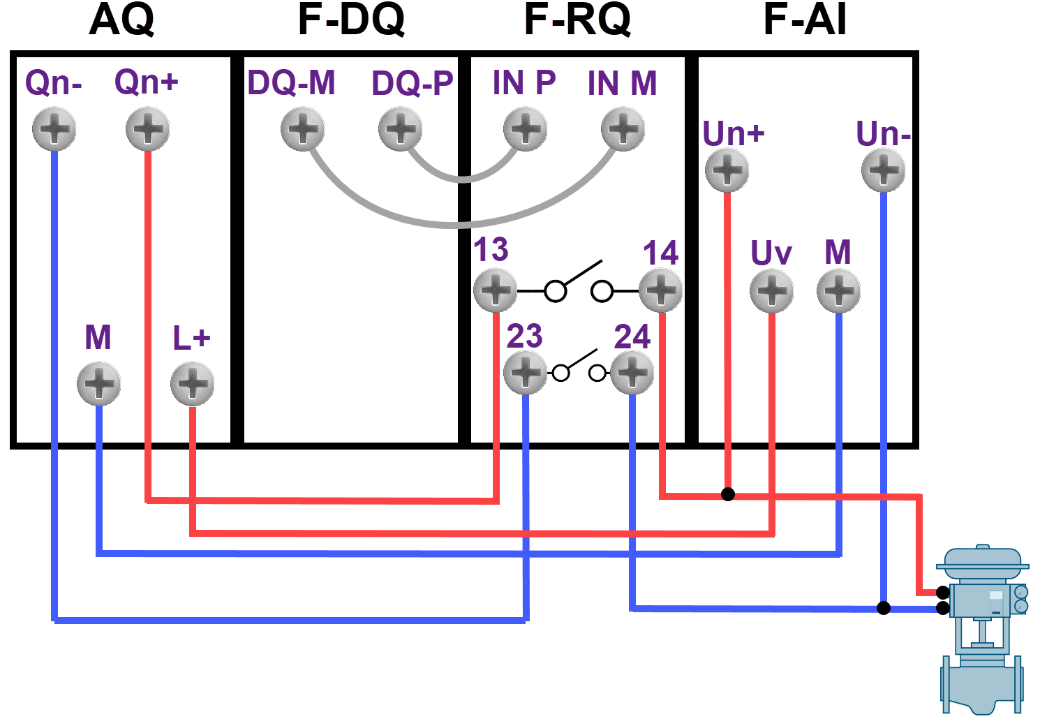
The output voltage or current of the standard analog output card for the actuator needs to be directed through the F-RQ card's relay contact, followed by reading it back via the F-AI card. The F-DQ card's relevant output (DQ-M and DQ-P) must be physically linked to the F-RQ card's input (IN M and IN P) to ensure connectivity.
To output current in the practical example, refer to the wiring shown in Figure 4.1.
To output voltage in the practical example, refer to the wiring displayed in Figure 4.2.
Parameter Configuration
Now, you will be provided with an overview of the parameter configuration for the individual channels of standard and fail-safe cards.
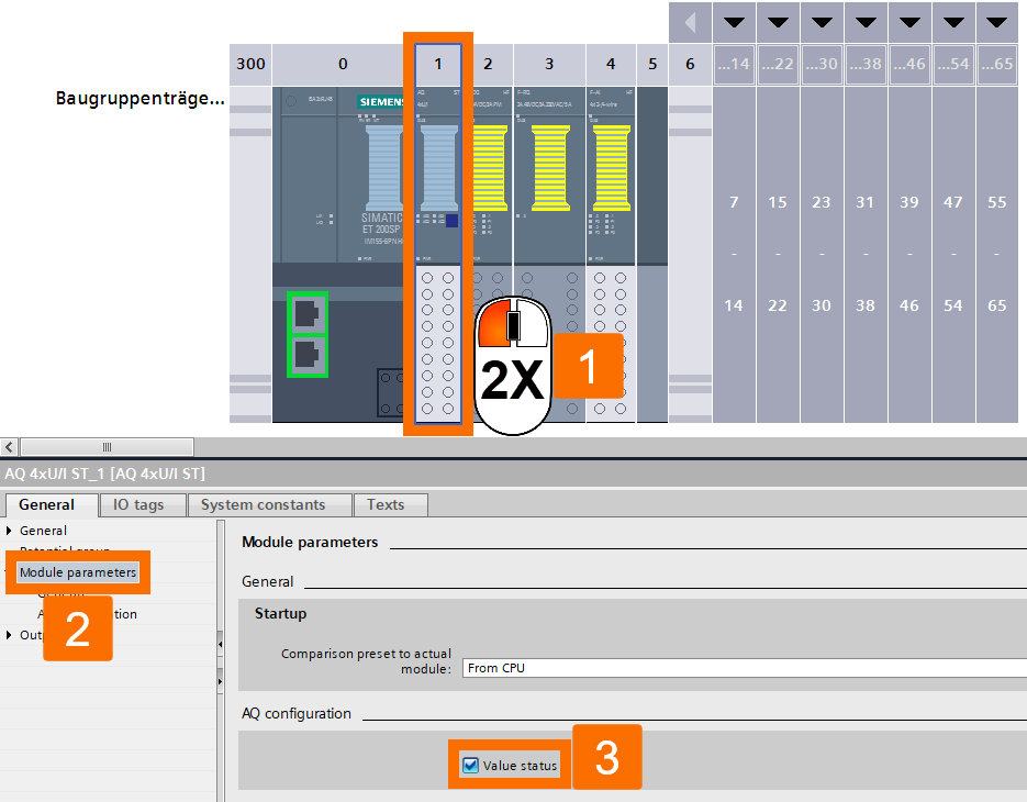
Double-click over the standard analog output card to open the inspector window. Under the General tab, left-click the Module parameters item, and then in the AQ configuration section, activate the Value status.
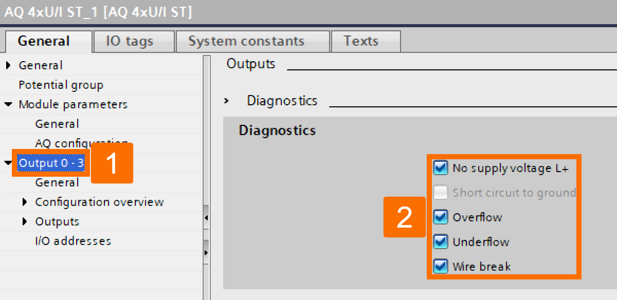
Now, select the Output item and navigate to the Diagnostics section. There, check boxes of No supply voltage, Overflow, Underflow, and Wire break.
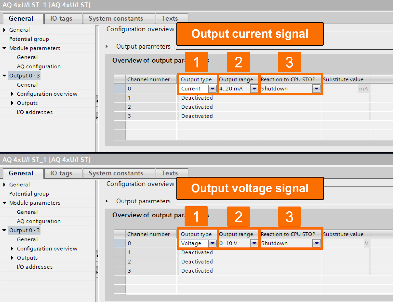
This time, head to the Configuration overview section and select your output signal type, which can be current or voltage. Also, choose the Shutdown option in case your CPU goes to stop mode.
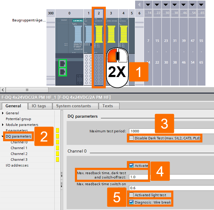
The ET 200SP F-RQ card is under the control of the F-DQ card. Double-click over the F-DQ card, select the General tab, and then choose the DQ parameters item. First, uncheck the Disable Dark Test box. Then, after activating the channel, set the Maximum readback time, dark test, and switch-off test to 1 ms. The parameter value of the Maximum readback time switch-on test is not relevant. How so? Since the Light test is supposed to be deactivated. Also, enabling the diagnostics for wire break is a must.
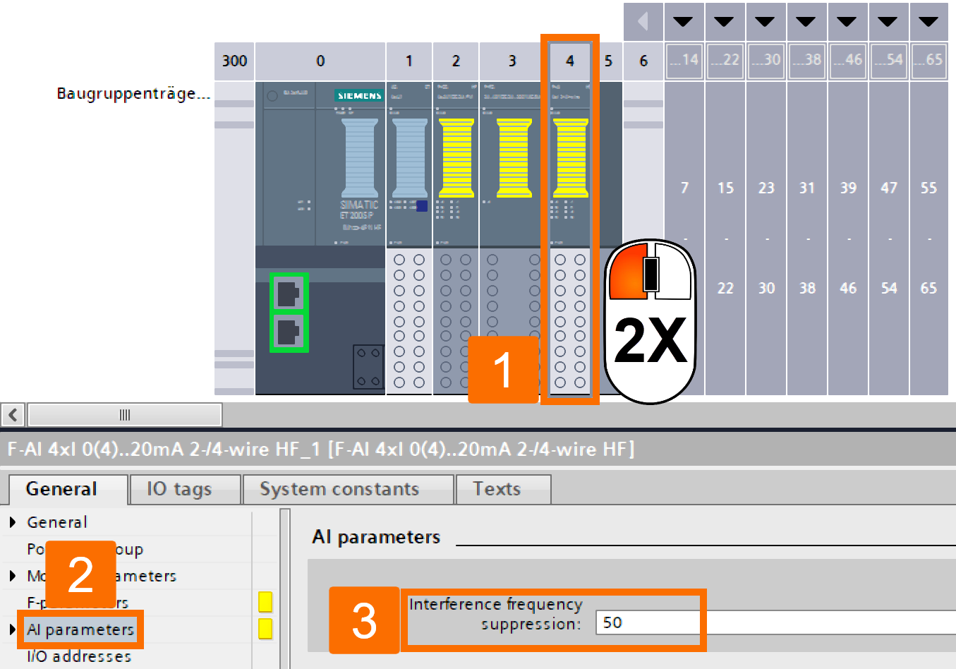
There is no need to adjust the parameters of the F-RQ card. Now, let's switch to the fail-safe analog input module. Double-click over this card and select the AI parameters item under the General tab. It will have better results if the Interference frequency suppression is 50 hertz.
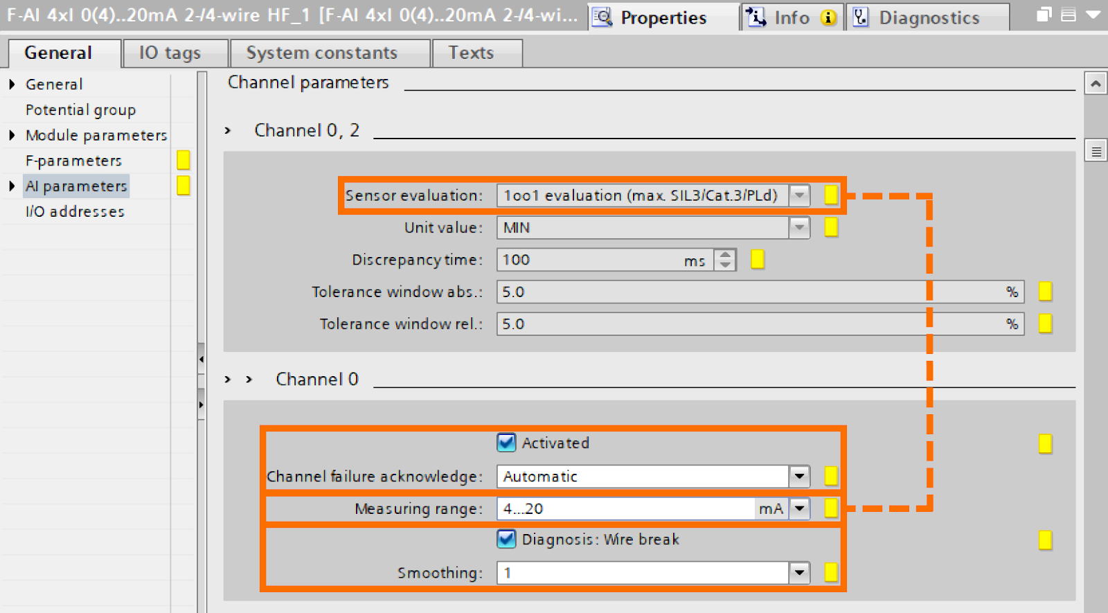
Navigate to the Channel parameters section. The parameter values of Unit value, Discrepancy time, Tolerance window abs, and Tolerance window rel are not relevant. For the channel, after activating it, set the Channel failure acknowledgment to Automatic. Enabling the diagnostics for wire break is a must, and also set the Smoothing parameter to one. If you want the fail-safe analog current measurement for analyzing discrepancies, set the Sensor evaluation to 1oo1 evaluation (max. SIL3) and then select the 4 to 20 mA as your measuring range.
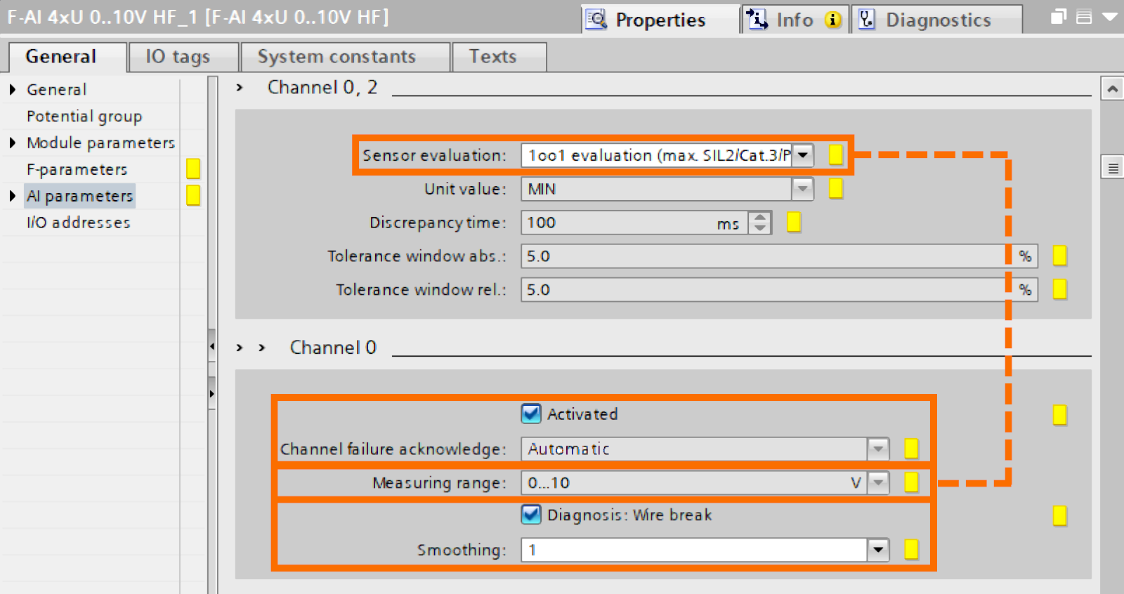
But, if you desire the fail-safe analog voltage measurement for analyzing discrepancies, set the Sensor evaluation to 1oo1 evaluation (max. SIL2) and then have 0 to 10 volts as your measuring range.
Description of the Interface
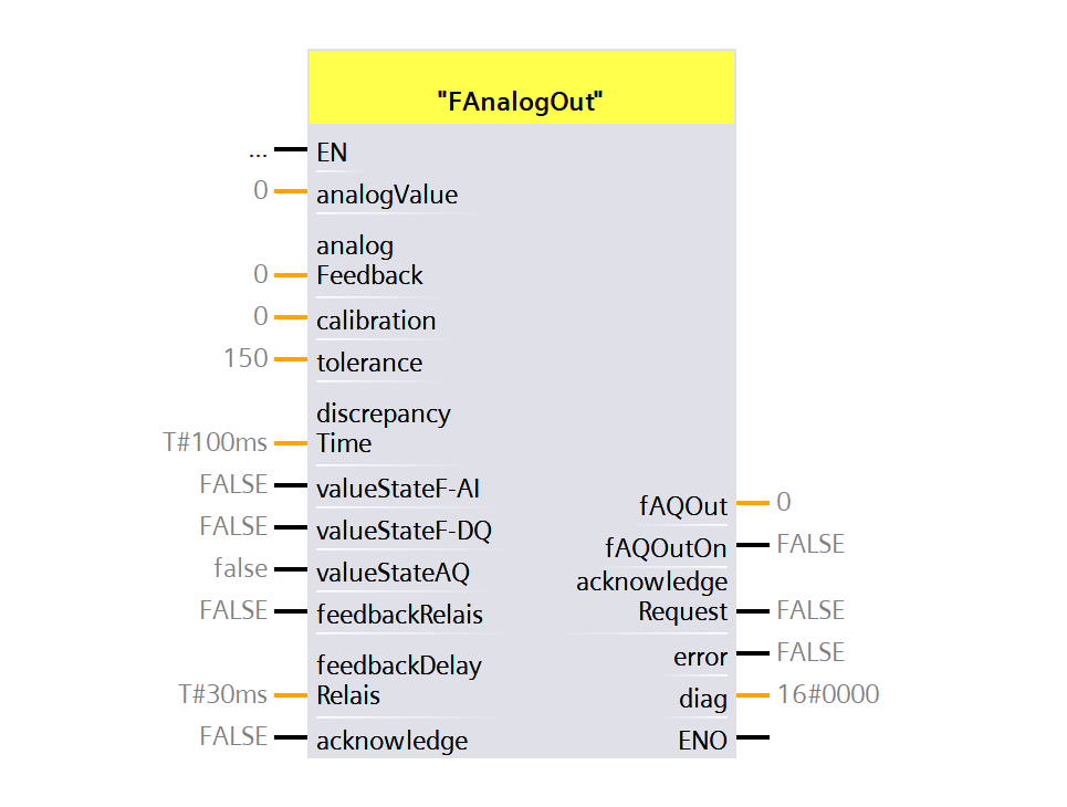
Now, you will be presented with a detailed explanation of the FAnalogOut block interface. This block represents the heart of this practical example.
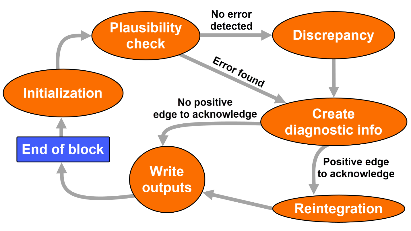
Within the FAnalogOut block, the state machine depicted in Figure 6.2 is operational. With each new cycle, the state graph begins in the Initialization state and concludes in the Block end state.
In the Initialization state, resetting the internal variables to the block's default values happens, allowing the cycle to start anew. Also, the block interface will be checked for invalid inputs.
In the plausibility state, fail-safe cards' value status will be evaluated. Also, the relay module's feedback input will be examined while considering the maximum delay time. Configuring necessary error bits occurs in this state too.
In the Discrepancy check state, it will be evaluated if there is a difference between "analogValue" and "analogFeedback" considering the provided values of tolerance and calibration. Configuring necessary error bits occurs in this state too.
In the Create diagnostic information state, the generation of the diagnostic word (for error-free situation: 16#0000) occurs. Also, a positive edge detection on the Acknowledge input will be examined.
In the Reintegration state and in the absence of any error, the analog values are re-evaluated, and the diagnostic word is set back to 16x0000.
In the Write outputs state, writing the fAQOutOn output, analog value forwarding to fAQOut, diagnostic word transferring to diag, and the aknowledgeRequest tag determination and routing occur.
In the End of block state, departing from the block occurs.
Incorporating Within the User Program
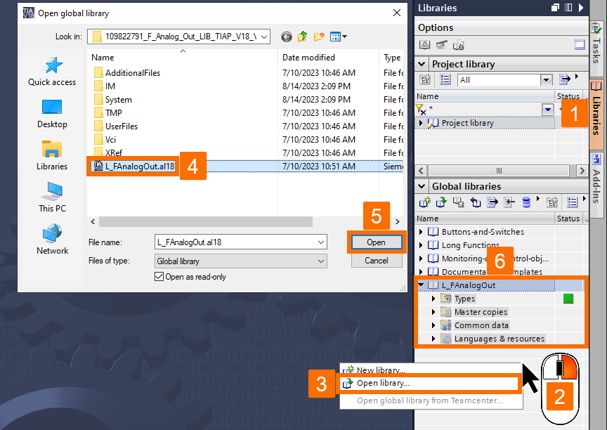
Now, you will be provided with a description of how the L_FAnalogOut" library ensures the safe output of an analog value. After downloading this library from here and unzip, open it in the Libraries task card.
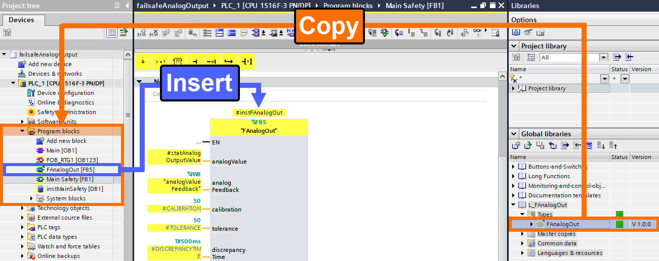
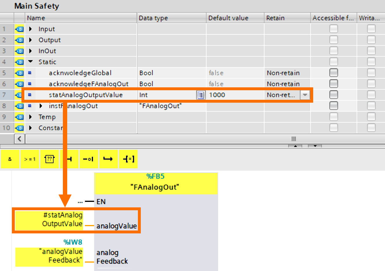
It is necessary to copy the FAnalogOut function block within the Program blocks folder and then insert it into the Main Safety function block to be executed.
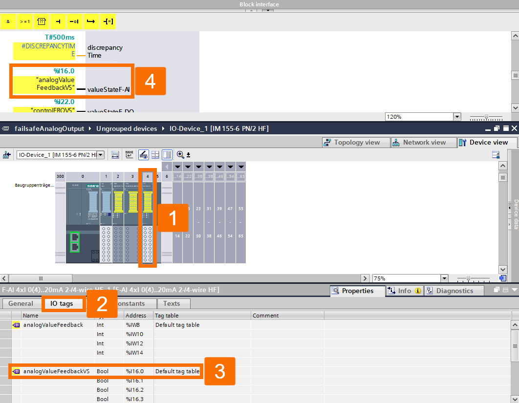
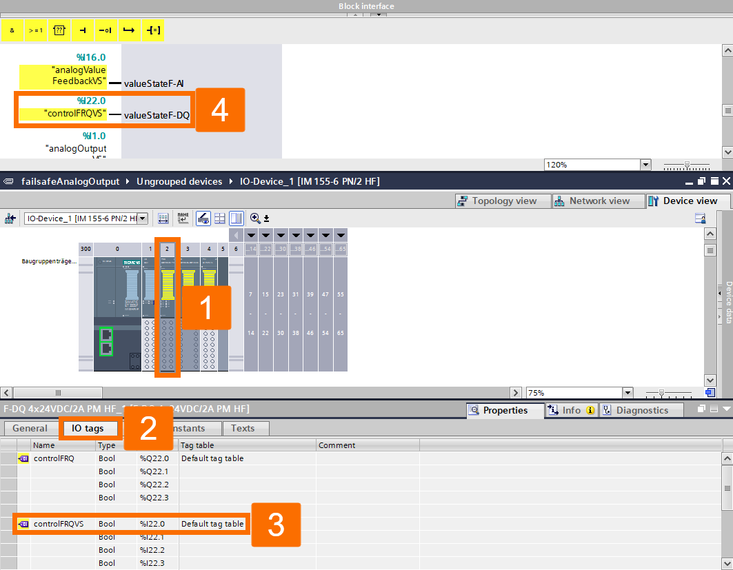
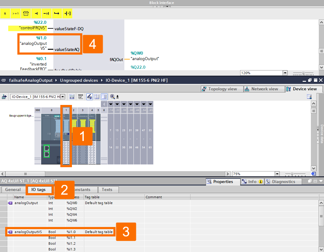
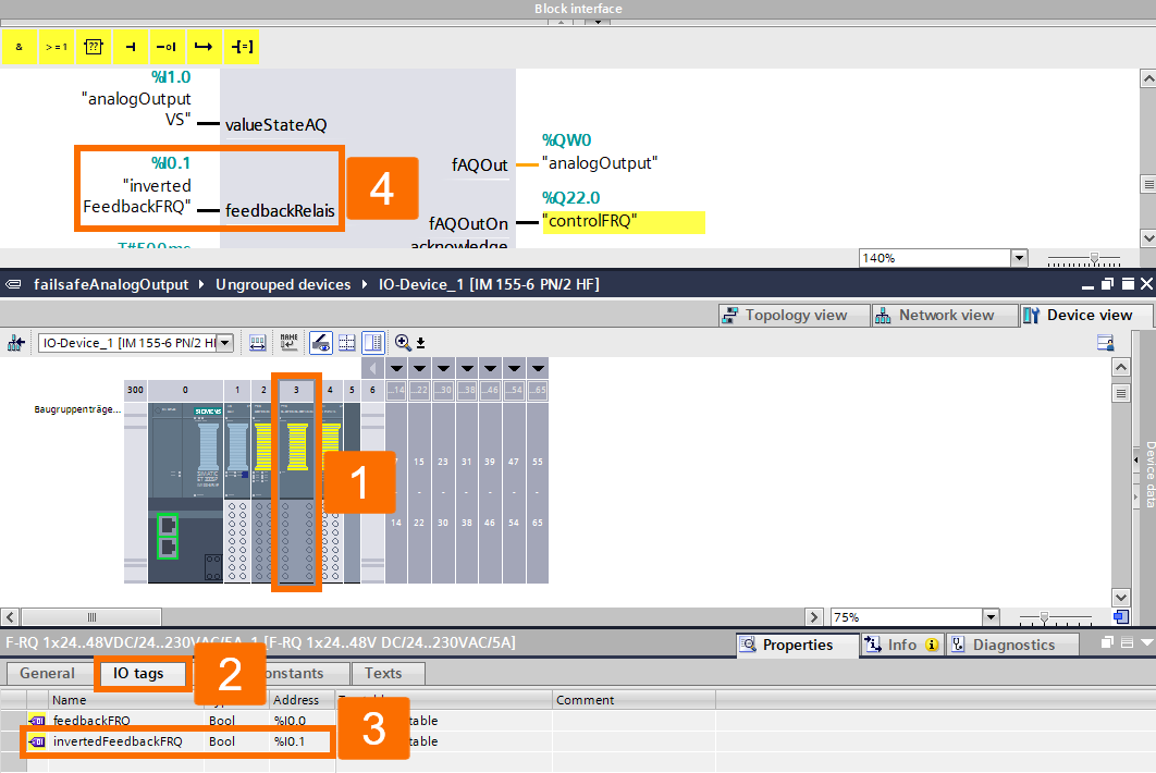
This time, you are presented with assigning inputs and outputs of the FAnalogOut block to suitable variables.
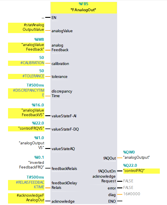
analogValue input: It represents an analog value that serves as the target or setpoint for the system's safety measures. The safety program is responsible for calculating this.
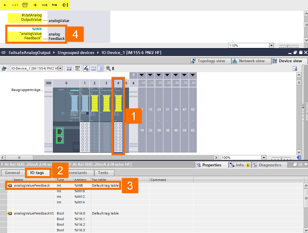
analogFeedback input: The fail-safe analog input card retrieves the actual analog value.
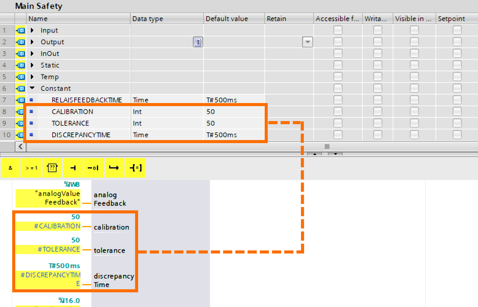
calibration input: Compensatory parameter for rectifying measurement errors. Value combined with analogFeedback.
tolerance input: Maximum allowable difference between the analogValue (the specified analog value) and the analogFeedback (the analog value that is measured) while considering the correction value for calibration input. Due to rounding and measurement inaccuracies, it is advisable to avoid setting the tolerance input too low.
discrepancyTime input: Period within which discrepancies between the analogFeedback and the analogValue beyond the tolerance threshold do not result in an error.
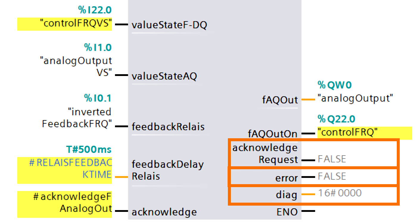
valueStateF-AI input: Interlinking with the value status of the associated channels in the fail-safe analog input card.
valueStateF-DQ: Interlinking with the value status of the associated channels in the fail-safe digital output card.
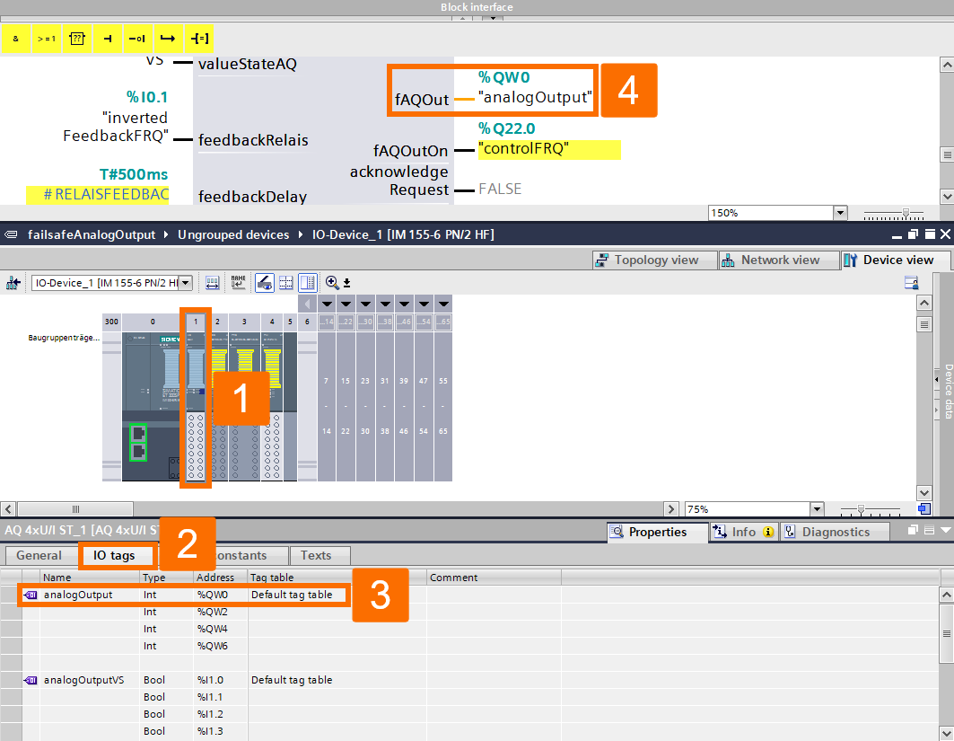
valueStateAQ: Interlinking with the value status of the associated channels in the analog output card.
feedbackRelais input: Interlinking with the F-RQ card's inverted readback channel.
feedbackDelayRelais input: The F-RQ card's readback channel must track the signal change of the output within a specified maximum time.
acknowledge input: Following fixing an error or startup, manual acknowledgment is needed to commence the block restart.
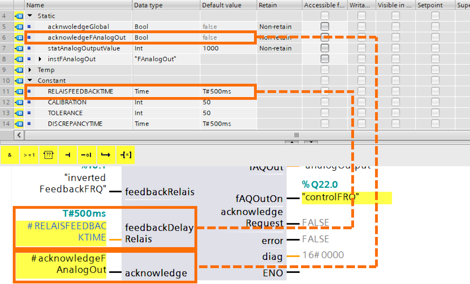
fAQOut output: Achieving control of the analog output card is done by this output value.
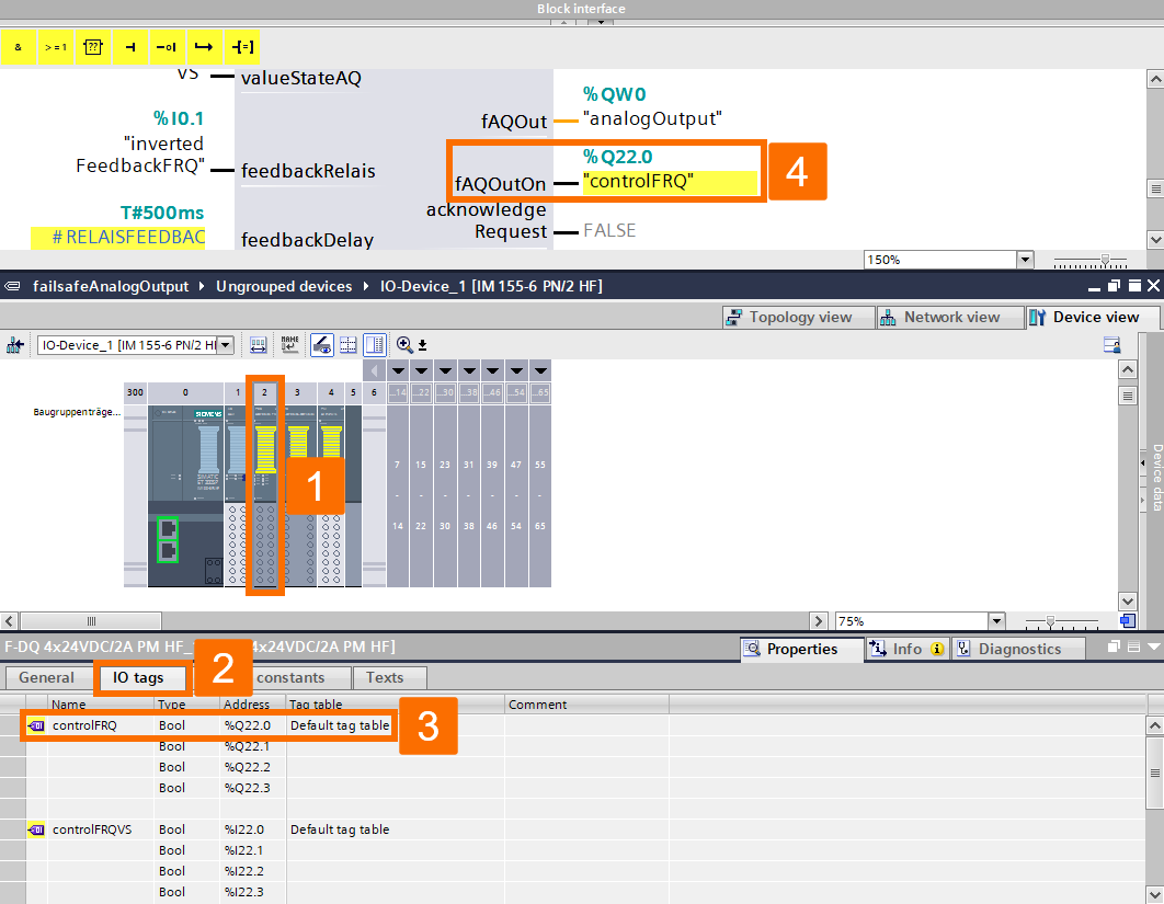
fAQOutOn output: Achieving control of the F-RQ card is done by this output.
acknowledgeRequest output: Indicates if an acknowledgment is necessary.
error output: The absence of errors or the presence of at least one error.
diag output: Comprising different error bits, the diagnostic word offers detailed insights into the error's root cause.
Fault Analysis
In the event of an error, the diagnostic word is wired to reflect the truth value of the error output which is TRUE. It is essential to assess the error bit and implement the plant response according to the risk assessment.
Bit
Detailing
Bit 0
Discrepancy alert. The duration of the discrepancy is still in progress, but the expiration has not been reached.
Bit 1
The block's inputs have been assigned incorrectly -> Inspect the values provided as inputs.
Bit 2
The F-AI card's relevant input is currently in a FALSE state.
Bit 3
The F-DQ card's relevant output is currently in a FALSE state.
Bit 4
Within the specified time, the feedbackRelais has not transitioned to TRUE as anticipated.
Bit 5
Within the specified time, the feedbackRelais has not transitioned to FALSE as anticipated.
Bit 6
An error indicating a discrepancy has occurred.
Bit 7
An overflow in the data range happened while computing the analogValue, analogFeedback, and calibration inputs -> Inspect the values provided as inputs.
Bit 8
The standard AQ card's relevant output is currently in a FALSE state.
Bit 9 through 15
Reserved
Table 8.1: Fault analysis of the FAnalogOut block - Diagnostic word composition
Conclusion
In conclusion, you learned about generating an analog output signal for a fail-safe system. You got familiar with the operating principle of the FAnalogOut function block for this purpose. You became acquainted with the suggested hardware configuration and wiring to output current or voltage signal. You understood how to configure the parameters of the standard and fail-safe cards. You figured out how to integrate the FAnalogOut block within the user program. And finally, you grasped fault analysis of the diagnostic word published by the diag output.
