How to Program PID Loops in RSLogix 5000

Introduction
The PLC was created to simplify the implementation of relay type logic control. The control implemented with the help of PLCs, have since evolved to more than mere sequence control.
The control solutions addressed by PLCs now include single input single output type PID control, feed forward control, and multiple PID loops in cascade control, to name but a few.
Different processes have switched from a manual to an automatic type control approach. This reduces and in a lot of cases eliminates human error, improves process/control stability, improves efficiency, and increases throughput and/or output.
Every control engineer should develop the skill and be able to use and implement PID control in simple control situations.
In this tutorial, you will get a fundamental understanding of the use of PID loops, and how to program them in RSLogix 5000.
Manual vs. Automatic Control
To appreciate the switch from one form to the other, let’s look at a simple example.
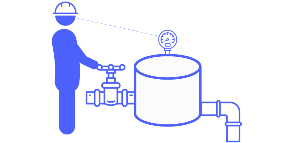
This is an example of Manual Level control. An operator visually monitors the level in the tank. The instruction was given to him to maintain a desired water level in the tank. The means he has to his disposal to carry out this task is by opening and closing this valve. When the tank level decreases below the desired level, he will increase the inflow by opening the valve and when the tank level increases to more than the desired level, he will close the valve. After some experience, he may realize that the valve must be open to a certain point to maintain the desired level, with a constant outflow.
The problem exists that there are multiple forms of human error that may occur, like:
- The level he perceives to be the desired level, might not be the same as instructed.
- He needs to take breaks throughout his shift and can’t monitor this process constantly.
- Some days he might be more exhausted and thus the control carried out will not be as required.
This simple process now utilizes an important human resource, that should be used more efficiently.
To make the switch, the setup for this example should change to a similar configuration as depicted below.
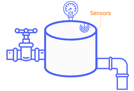
Here the human element has been removed. The visual monitoring that was done by the operator, is now carried out by a Level Transmitter, which is constantly measuring the level inside the tank. The final control element is replaced with a pneumatic control valve.
Converting this example to P&ID form will look as follows:
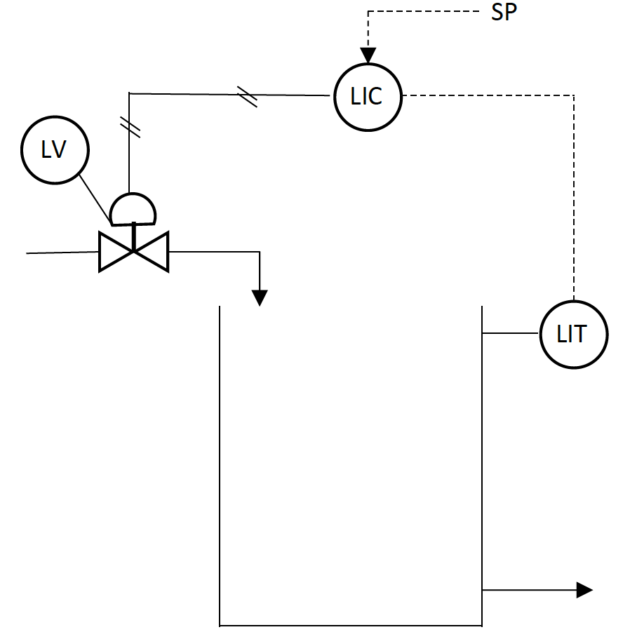
The process controlling, decision-making process that was carried out by the operator is now replaced with the Level Indicating Controller. The desired tank level serves as a Setpoint (SP) input to the controller. The controller compares the desired level setpoint, with the physical level measurement (PV). Depending on the magnitude of the difference, the controller responds by changing the output (OP) to the valve to change the inflow and get the tank level to the desired point.
The Automatic process of controlling this tank level eliminates the drawbacks as experienced by a Manual operator process. Automatic control may be achieved by either installing a stand-alone PID controller or by connecting the instruments (I/O) to a PLC and using the built-in PID control functionality.
The PID Instruction
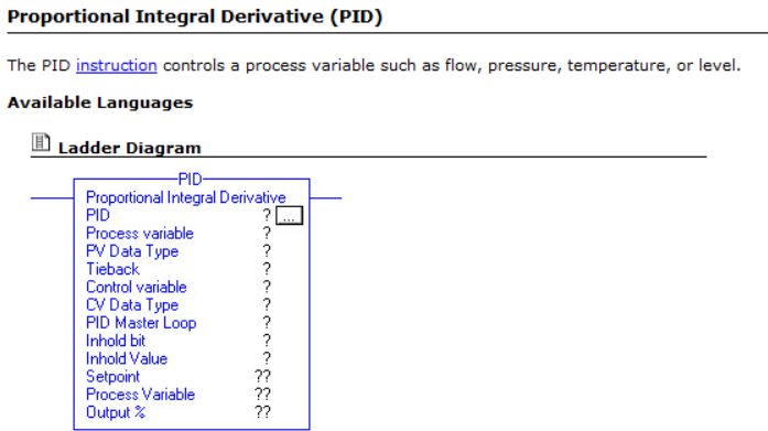
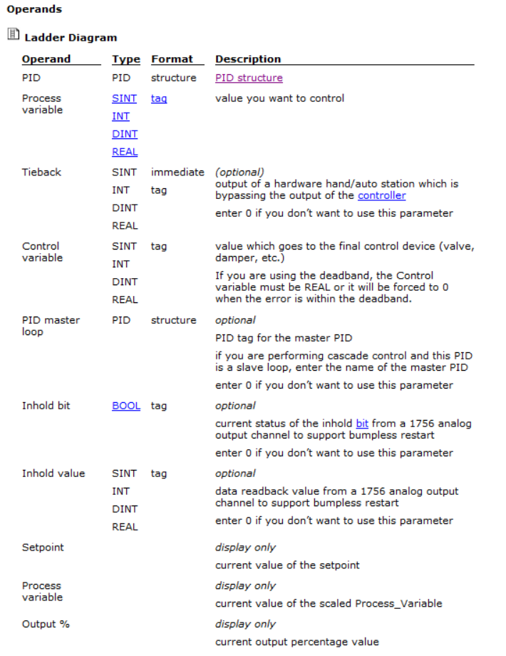
The two images displayed are retrieved from the RSLogix5000 software’s help files. For completeness, all operands are displayed, but only the key operands which will be used in the majority of the cases will be discussed.
The key input operands are:
- PID: In this field, a unique tag must be used to address the specific control loop. After this tag has been created, all members of the Data type may be accessed by using the tag together with a suffix. Example: LevelControl.SP to use the Setpoint member of the data type.
- Process Variable: In this field, the Analog input tag is used to input the measured value (PV) that must be controlled.
- Control Variable: In this field, the Analog output tag is used where the output from the controller must write to the final control element.
The key output operands are:
- Setpoint: The desired value (SP), to where the process must be controlled is written to PID.SP and is displayed here.
- Process Variable: The current value of the Analog input is displayed here.
- Output %: The control variable’s value or controller output value (OP) is displayed here.
Tasks
This is a topic that needs brief attention before the actual programming occurs. When a new project is created in RSLogix 5000, the following basic configuration under the tasks folder is created automatically.
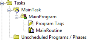
‘MainTask’ is automatically created, hosting the ‘MainProgram’. In the folder, a circular arrow can be seen. This indicates that ‘MainTask’ is a continuous task. A continuous task is one that runs continually. It will sequentially scan through all the assigned programs, as scheduled by the programmer. Once the task has finished executing, the whole process will be repeated. The speed at which this occurs may gradually decrease over time, as the project expands or may even drastically increase when the controller is upgraded to a faster controller.
This will have an adverse effect on PID loops. The ‘tuning’ of parameters for a PID loop is in fact the changing of variables for different calculations. When the speed at which a continuous task is scanned changes, the frequency of how often the calculations inside the PID instruction is executed also changes. This, in turn, affects the frequency of output changes that is sent to the final control element and thus the control loop may not react as to how it was initially configured.
To eliminate the chances of this happening, a different type of task may be created to host the program where all the routines implementing PID instructions are assigned to be executed. This type of task is called a periodic task.
The icon for this task, as depicted above, looks like a watch. This type of task only executes after a pre-set time (period) has elapsed. Executing the PID instructions inside a periodic task ensures that the frequency remains the same, overcoming the possible problems that may be experienced with the continuous task.
Programming a PID instruction in Ladder Logic
With the fundamental understanding of why and when a PID instruction will be used, together with the where it should be implemented, the how part will now be discussed. There are a few steps that must be completed before continuing with this tutorial:
- A new project must be created in RSLogix 5000.
- The Analog input module for the input from the measuring instrument must be added to the project.
- The Analog output module for the output to the final control element must be added to the project.
For this PID tutorial I decided to use the following hardware:
- L61 controller running version 20 firmware in slot 0.
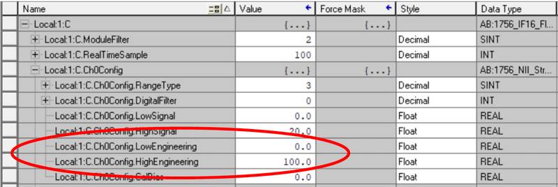
- 1756-IF16 Analog Input module, in ‘Single-Ended Data-No Alarm’ mode, in slot 1.
- 1756-OF8 Analog Output module in slot 2.

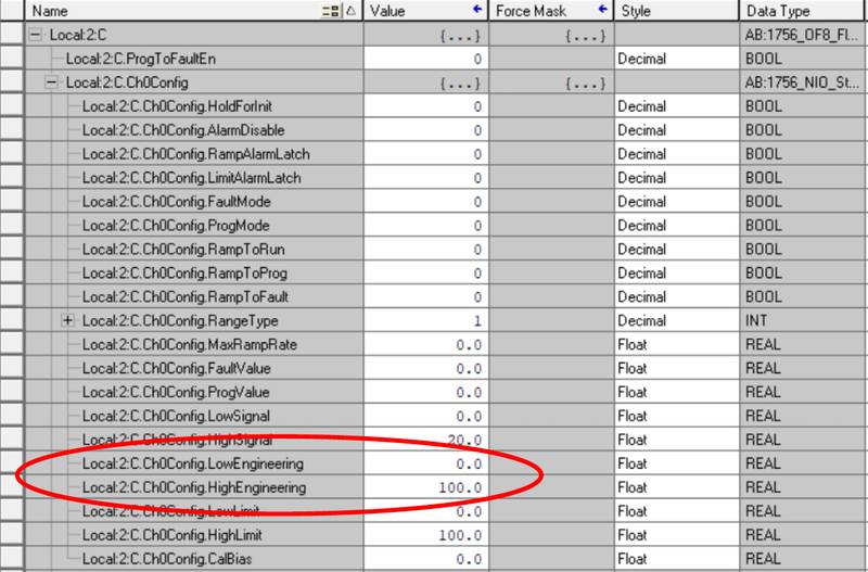
The Engineering unit scaling range for both inputs and outputs are 0 – 100, as can be seen in the images below.
After the preliminary steps have been completed, the programming may commence.
Step 1 – Creating a Periodic Task
As discussed previously, it is advised to execute the PID instructions from within a Periodic task. The first step is to create the needed periodic task.
- In the Controller Organizer pane, right-click on Tasks and select ‘New Task…’.
- The New Task window appears.
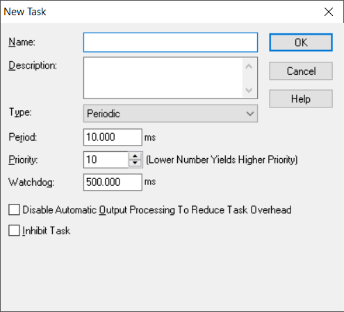
- In the Name field, type in PID_Loops.
- Ensure that Periodic is selected in the Type drop-down.
- Change the period to 250 ms.
- The rest of the default settings may be left as is.
- Click OK when finished.
A new periodic task is created.
Step 2 – Creating a Main Program for the new task.
The next step is to create a Program assigned to the periodic task.
- Right-click on PID_Loops and select ‘New Program…’.
- The New Program window appears.
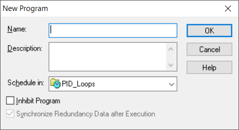
- Give the program a name called ProcessControl.
- Click OK when finished
- A program must have a ‘Main’ routine assigned to it. Right-click on the ProcessControl program and select ‘New Routine…’.
- The New Routine window appears.
- Give the routine a name called MainRoutine.
- Note that Main is selected in the Assignment drop-down, as the Program does not have a Main Routine assigned to it yet. Leave the rest on the default selections and press OK.
Step 3 – Creating a new Routine for the Tank’s Level Control
The main routine has been created that will be used to call the different subroutines that will be created throughout the project life for all the different types of PID control implementation. The first control subroutine will now be created.
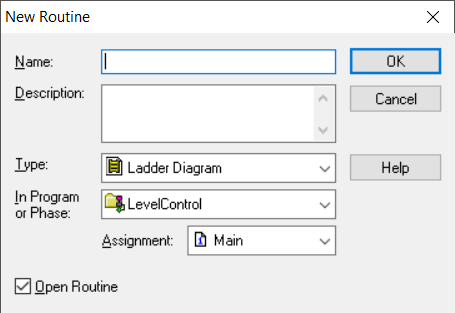
- Once again, right-click on the ProcessControl program and select ‘New Routine…’.
- The New routine window appears again, but this time the new routine must be named LevelControl and the Assignment drop-down must show <none>.
- Click OK.
- If both routines are not open, then the Open Routine checkboxes were not selected. If this is the case then double-click on MainRoutine, as well as on LevelControl.
- Click on the MainRoutine tab, to make sure that MainRoutine is the current active open routine.
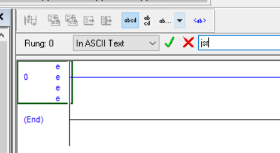
- Insert the Jump to Subroutine instruction in Rung 0. This can either be done by selecting JSR in the Program Control group

or by double-clicking on the left of Rung 0 and entering JSR in the ASCII Text field.
- Double click on the Question Mark (?) next to Routine Name and select LevelControl from the drop-down.
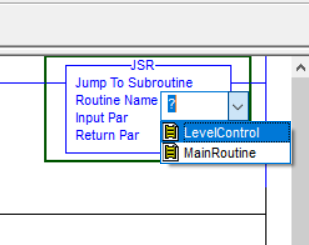
- Clear the ‘Input Par’ and ‘Return Par’ fields.
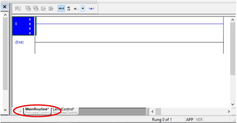
- The MainRoutine should now look like this.

Every 250 ms the PID_Loops periodic task will be executed. In turn, the Task will execute all assigned programs. In this case, it is only the ProcessControl Program that is assigned. When the program is executed, the associated routine with the ProcessControl Program will be called to be executed. In this case, it is the MainRoutine that has been created. When the MainRoutine is executed, the instruction that is given to the controller in Rung 0 is to Jump to a Subroutine. So, in rung 0 execution will be shifted to the LevelControl routine. After the LevelControl routine has been executed, the rest of the MainRoutine will be scanned until finished and thus the execution of the Periodic Task is complete.
Step 4 – Programming a LevelControl Routine
Since the frequency of how often the routine will be executed has been addressed as well as directing the controllers’ flow of execution to the Routine where the PID instruction will be called, the actual implementation may now be done.
- Ensure that the LevelControl routine is the active routine by clicking on the LevelControl tab.
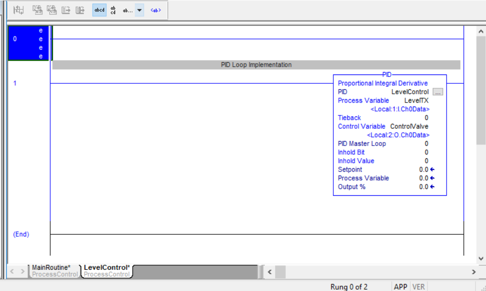
- Right-click on Rung 0 and select ‘Edit Rung Comment’

- Change the rung comment to ‘PID Loop Implementation’
- Browse to the ‘Special’ Element Group and select PID. Alternatively, double-click on rung 0 and enter ‘PID’ in the ASCII Text field.
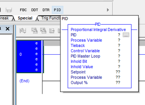
- The PID instruction should now be in Rung 0.
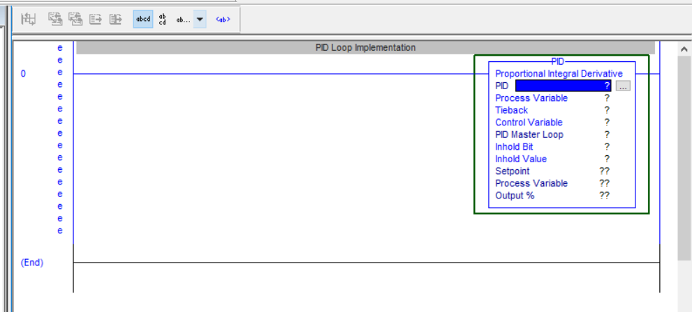
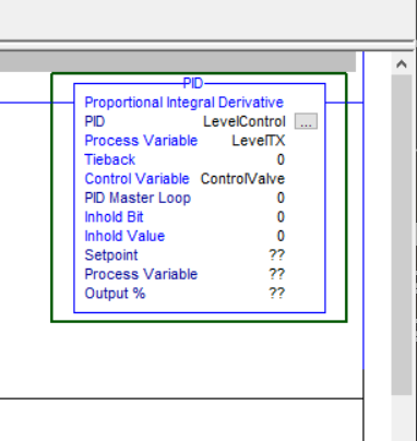
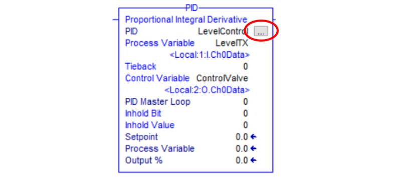
- Next, input the key input operands and change the optional operands to 0 as follow:
PID: LevelControl
Process Variable: LevelTX
Tieback: 0
Control Variable: ControlValve
PID Master Loop: 0
Inhold Bit: 0
Inhold Value: 0
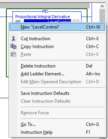
- The tags that have been inserted has not been created yet. Right-click on the LevelControl tag and select ‘New “LevelControl”’
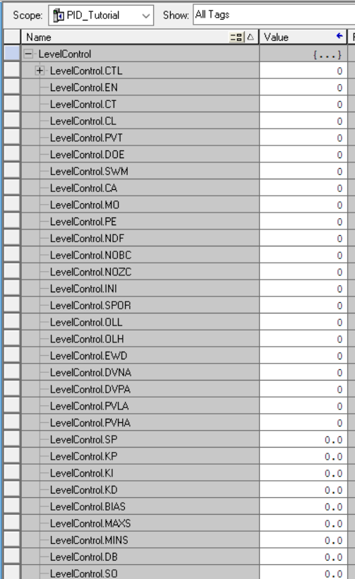
- The New Tag window appears. Note the default Data Type: PID.

- Click Create. The LevelControl tag has now been created as a PID Data Type, together with the members associated with the data type. This can be seen in Controller Tags.
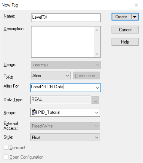
- Right Click on the LevelTX and select ‘New “LevelTX”’
- Change the Type to Alias and in ‘Alias For’ drop-down, browse to ‘Local:1:I.Ch0Data’.
Note: If the Analog is connected to a different channel on the Analog Input Module, that specific channel must then be selected.
- Do the same with the ControlValve tag, but this time select ‘Local:2:O.Ch0Data’, unless a different Analog Output Channel has been used.
The PID instruction has been successfully implemented. Next, we want to make sure that the setpoint (SP) that is given to the PID is within limits. This may be limited to the physical limits of the process. In this example that is 0 – 100% of the tank level. Alternatively, it may be limited between a minimum and maximum allowed range, as allowed by the process, for example, 40% - 60% of the tank level.
- Right-click on Rung 0 and select Add Rung. Rung 1 is added to the routine.
- Click and hold Rung 1 then drag and drop it, so that the empty rung moves to the topmost rung in the routine.
- Edit Rung 0’s rung comment and enter ‘Setpoint Limits’
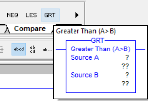
- Insert a Greater Than instruction to rung 0, by either selecting it from the Compare Element Group or typing GRT in the ASCII Text field.
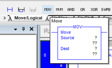
- Also, insert a Move instruction by selecting it from the Move/Logical Element group
- Edit the rung so that it looks like the following.
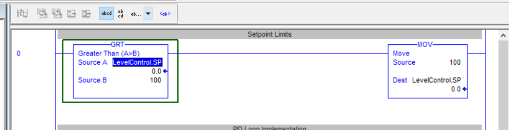
This rung will now test if the Setpoint to the PID is more than 100. If it is more than 100, it will move 100 into the Setpoint.
- Add a rung below Rung 0 and insert a Less Than (LES) instruction, as well as a Move (MOV) instruction, and edit it so that it looks like the following.
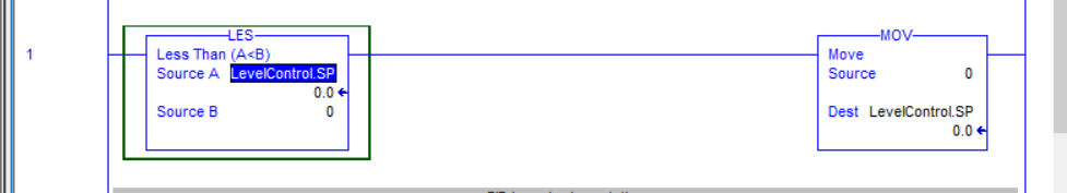
This rung will test if the Setpoint to the PID is less than 0. If it is, then move 0 into the Setpoint. These two rungs effectively ensure that the Setpoint to the PID is within the 0 – 100 % limits. They are intentionally placed before the PID instruction to ensure that the setpoint is within limits before the calculations in the PID instruction is executed.
- Insert an empty rung and move it to Rung 0.
- Change the rung comment to ‘Auto/Manual Select’
- Insert an Examine On instruction by selecting it from the Bit Element Group

- Change the tag for the bit inserted to ‘Auto_Manual’.
- Right-click on ‘Auto_Manual’ and create a new tag with Type: Base and Data Type: BOOL.
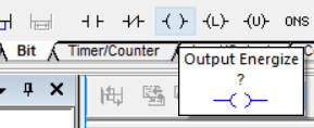
- Insert an Output Energize instruction by selecting it from the Bit Element Group, after the instruction that was just inserted.
- Browse the tag for the bit inserted to find the software manual member of the PID tag, LevelControl.SWM
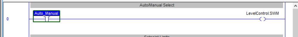
This rung is placed here to easily switch between Manual and Auto mode for the PID control.
- The PID instruction must still be configured. To do this, left-click on the ellipsis on the PID instruction.
- The PID Setup – LevelControl window appears with the Tuning tab selected
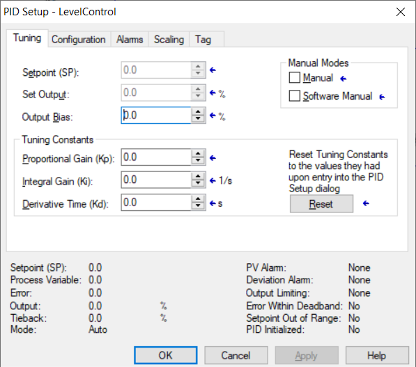
- When you click on the Help button while in any of the windows, the Help displayed will explain the details pertaining to the active window.
- As an initial configuration, change the Proportional Gain (Kp) to 0.5 and the Integral Gain (Ki) to 1.0.
Note: The explanation of the effect of PID parameter tuning is outside the scope of this tutorial.
- Click Apply and then select the Configuration Tab.
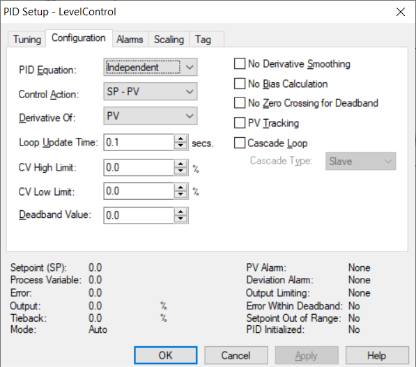
- On the PID Equation drop-down, select Dependant. This option changes the controller gain to affect all three terms (Proportianal (P), Intgegral (I) and Derivative (D)).
- The Control Action changes how the error between the Setpoint and Process Variable is calculated. This in turn affects the Control Variable (Output) of the controller, if it increases or decreases according to a specific error.
- Change the Loop Update Time to 0.1 seconds.
- Change CV High Limit to 100%. This allows the output to go up to a maximum of 100%.
- Change CV Low Limit to 0%. This allows the output to go down to a minimum of 100%.
- Click Apply and then select the Alarms Tab.
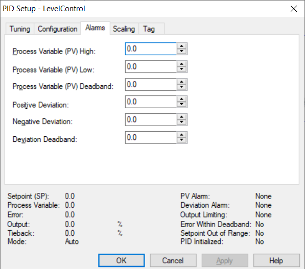
- Change the Process Variable (PV) High to 100.
- Click Apply and then select the Scaling Tab.
- The programming has now been completed and the project may be downloaded to the controller.

- Change the following fields in the Process Variable (PV) section to represent how the Analog input has been configured:
Unscaled Max.: 100
Unscaled Min.: 0
Engineering Unit Max.: 100
Engineering Unit Min.: 100
- Change the Control Variable (CV) fields to represent the full range the output to the final control element must be able to change.
Max. (at 100%): 100
Min. (at 0%): 0
- Tick the PID Initialized checkbox.
- Click on Apply and then click on OK.
Conclusion
In this tutorial, we have covered the basic implementation of the PID instruction. This basic form of process control can greatly benefit the stability and efficiency of many processes, as has been discussed. Understanding the full capabilities of the instruction is key to using it in different scenarios. This can only be achieved by further reading and also playing around with it.
