PLC Programming | How to Read Ladder Logic & Ladder Diagrams

What is Ladder Logic & Ladder Diagram?
Ladder Logic is one of the top 5 most popular types of PLC programming languages used in manufacturing environments. Before Programmable Logic Controllers, manufacturing plants employed relay-based circuitry to energize different loads based on how the relays were wired together. The circuit patterns used for these drawings are known as ladder diagrams. Relays were costly, required constant maintenance, and could not be easily reconfigured. As PLCs took over this process, it was essential to keep a similarity of the old system; thus, ladder logic was created as the first PLC programming language.
Ladder Logic is labeled as such because the software is laid out in the shape of a ladder. On the left side, ladder logic instructions are set as conditions, while the ones on the right side are instructions that are triggered if the conditions are met. Each rung of the ladder spans from left to right and is executed from top to bottom by the PLC.
As mentioned above, ladder logic is extremely popular among PLC programmers. It’s easy to learn, mimics electrical circuits, and is easy to troubleshoot once deployed.
Learning ladder logic is typically the entry point into a career in control systems as a PLC programmer. In this post, we will go over ladder logic components, cover basic principles, and outline what it takes to master this programming language.
Learning to Read Ladder Logic Is Foundational
Before you can confidently write or troubleshoot ladder logic, you need to understand how to read it. Just like reading blueprints is essential before constructing a building, interpreting ladder logic diagrams allows you to understand how a machine or process is expected to behave. This skill is critical for debugging problems on the plant floor, identifying programming issues, or making safe, effective changes to a control system.
Ladder Logic Basics
Just like computers, PLCs operate with binary signals; each one can be set to zero or one. In the programming world, this data type is called a boolean. A boolean takes a single bit in the memory, can be set to 0 or 1, and is used in most basic PLC instructions.
The PLC executes the program loaded into it one rung at a time. As the PLC begins to process the rung, it reads the instructions on the left and determines if the Logic on that side of the rung is set to TRUE. The Logic evaluates to TRUE when a hypothetical current is able to pass through the instructions. Each instruction has a set of conditions that make it TRUE or FALSE.
For the purpose of this tutorial, we’ll start with two of the most basic instructions in ladder logic plc programming: Examine if Closed and Output Energize.
Examine If Closed [XIC] - This input instruction will look at the specified boolean bit and evaluate the condition to TRUE when the bit is set to 1 (or HIGH). While the bit is set to 0 (or LOW), the instruction will evaluate to FALSE.
Output Energize [OTE] - This output instruction will set the specified bit to 1 (or HIGH) if the input instruction conditions are TRUE. If they’re FALSE, the Output Energize instruction will set the bit to 0 (or LOW).
Basic Ladder Logic Rung Analysis
- Step 1 - The hypothetical current starts moving from left to right.
- Step 2 - When the hypothetical current encounters and XIC Instruction, it checks if the condition is TRUE or FALSE. If the XIC is False, the PLC aborts this rung.
- Step 3 - The hypothetical current goes to the next instruction. Repeats Step 2 until the rung is completed.
- Step 4 - The PLC moves to the rung below.
In the example above, the XIC Instruction is tied to the bit “Condition1”. Since the bit is OFF (or 0), the hypothetical current stops at the instruction.
In the example above, the XIC Instruction is tied to the bit “Condition1”. Since the bit is ON (or 1), the hypothetical current is allowed to pass through and goes to the OTE Instruction. The OTE Instruction sets the “Energize1” bit to HIGH (or 1).
Ladder Logic Structure | Circuit Branches
Now that we’ve seen a basic example that illustrates how the execution of a single ladder logic rung is completed, it’s time to discuss circuit branches. Circuit branches create a way for the current to pass through a different path as the rung executes. The instructions are executed in the same way, but we now need to analyze different paths the current may take.
The rung above has the primary rung and a branch that jumps the first two conditions with a 3rd one. Let’s analyze what’s happening with the execution of the Logic.
- Step 1 - The hypothetical current starts on the main branch of the rung. As it reaches “Condition1”, it evaluates the XIC Instruction. The XIC Instruction is TRUE and allows the current to proceed.
- Step 2 - The hypothetical current flows to the next XIC Instruction and attempts to evaluate it. Since “Condition2” is set to 0, the XIC Instruction evaluates to FALSE. The current is stopped.
- Step 3 - The hypothetical current goes back to the first branch. The XIC Instruction tied to bit “Condition3” is executed. Since the “Condition3” bit is HIGH, the XIC evaluates to TRUE. The current proceeds.
- Step 4 - The current reaches the OTE Instruction and sets the “Energize1” bit to ON (or HIGH).
Here's a much more complex example for you to consider. It's not abnormal to find multiple branched circuits in ladder logic.
Advanced Circuit Branching Ladder Logic Practice
Now that you’re familiar with how circuit branches work in ladder logic, it’s important to practice tracing the logic as you would in the field. Most of your work as a PLC programmer is going to be looking at rungs of logic and figuring out why the output is energized or what’s preventing it from turning on.
Consider the following situation: your supervisor calls you due to a problem on a production line. For some reason, the pump that’s going to deliver raw materials to a specific tank isn’t turning ON. As you show up to the operator station, he shows you that when he pushes the button, the pump won’t do anything.
Resolution: you look at the panel, press the button yourself, and confirm that it doesn’t start. This pump worked in the past, so you decide to see what’s happening in the PLC logic. As you trace the output tied to the pump, you notice a complex rung with multiple circuit branches. The reason is that there are numerous conditions for that pump to start. Since you’re familiar with the approach above, you can quickly figure out that the pump wasn’t able to start because one of the start conditions was that the tank must be empty. As you realized that the tank was, in fact, empty, the conclusion was that the level sensor was broken. You replaced the sensor, and the pump resumed regular operation.
Ladder Logic RSLogix 5000 Components
Now that we have some familiarity with how a basic rung structure is laid out, let’s discuss other components of ladder logic.
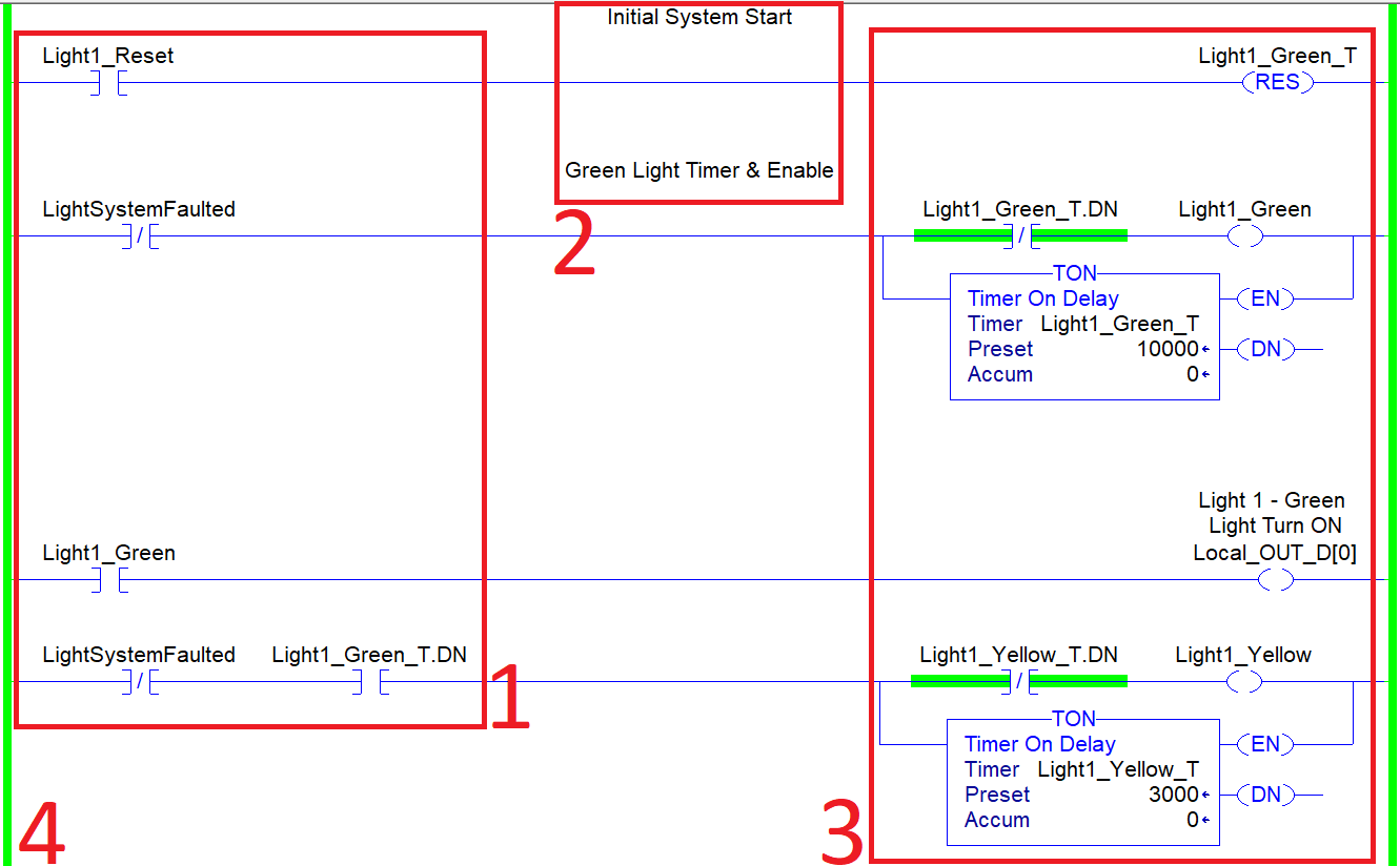
1 - Ladder Logic Inputs
As we discussed above, the ladder logic instructions on the left side are called inputs. Their condition is evaluated on a true or false basis. If the evaluation is concluded with a TRUE, the output of the ladder logic rung is executed. If it's evaluated to FALSE, the PLC goes to the following rung.
2 - Ladder Logic Rung Comments
Every programming language allows the user to add documentation to their software. In ladder logic, this opportunity comes with every rung, instruction and data structure. By adding a comment above the rung, you're making it easier for the person after you to understand your train of thought and troubleshoot the logic as needed. Furthermore, the comments may be used to indicate a change or temporary fix of a certain problem that was encountered by a PLC programmer.
3 - Ladder Logic Outputs
There are many instructions that will execute on the output side. In the example we covered above, our focus was on the OTE Instruction. However, the screenshot above also includes TON or Timer On Delay Instructions. As you gain experience as a PLC programmer, you'll encounter and master additional instructions.
4 - Ladder Logic Rails
Each rung of ladder logic lies between the two side rails (just like a regular ladder). These rails are what energizes each rung as they are executed. In the screenshot above, you can see two rails within the RSLogix / Studio 5000 environment. The rails remain grayed out until the main routine calls the program. In the screenshot, the rails are green, which means that this specific logic is being executed.
5 - Tag Names
Each instruction will be tied to one or more tags. Each tag requires a data structure element as well as a name or label. In the examples we looked at above, tags were labeled as "Condition1", "Condition2", "Condition3", etc. In production circumstances, tags would typically reflect the physical element they control or a set of PLC based tags. For example, tags that control motors may have the label of MTR1_Start, MTR2_Stop, MTR2_Status, etc. Furthermore, tags may also have a description that allows the user to give the tag a text-based description.
Ladder Logic Programming in RSLogix 5000 Basics
As you invest yourself in PLC Programming, you'll quickly realize that the list of different instructions available to you is vast. Furthermore, as you become advanced at the craft, you may find yourself creating your instructions through the use of an Add-On-Instruction or AOI. However, assuming that you're here for the basics, let's discuss the most useful instructions you should start working with as you tackle industrial automation.
Examine If Closed [XIC]
We've looked at these instructions at the start of the tutorial. It's the essential input check you can make on your data. In short, if the boolean assigned to the XIC is TRUE, the output will go through. If it's FALSE, it won't. Although it may seem that this would have limited utility, many of the advanced constructs within PLCs have a boolean state. For example, a Variable Frequency Drive may have an array of boolean structures that are tied to different faults. Therefore, you may create the same number of XIC instructions to verify which failure is present on the drive.
Examine If Open [XIO]
The XIO will energize the output if the exact opposite of the XIC is true. In other words, the output will energize if the boolean value is FALSE.
Output Energize [OTE]
The OTE is an output instruction and will set a boolean to TRUE if all the preceding conditions are TRUE leading to it. The OTE would also set the boolean to FALSE should there be no TRUE path of inputs leading to it. The Output Energize instruction is used to set digital outputs on field devices such as valves, motor contactors, relays, solenoids and more.
Timer ON [TON]
Timers are a basic data-structure of PLCs. They allow the user to create a condition that will start an internal timer and execute an action based on what the user has programmed.
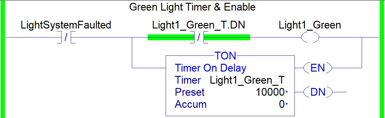
The most basic timer instruction is Timer ON or TON. This instruction will start counting as soon as the input is energized. The timer will continue timing until it reaches a value specified by the user. A PLC programmer can use boolean status bits of the timer in order to execute logic based on the timer running, completed or not-running status bits. This instruction is fundamental in PLC programming and is often seen in basic sequences, de-bouncing logic and any other programs that require timed execution of ladder logic.
Basic Motor Control Circuit - PLC Programming Ladder Logic Example
One of the most iconic first circuits a PLC programmer must master is a motor starter. Although it is possible to wire motor starter to work without the use of a PLC. There are many benefits to wiring the inputs and outputs into the controller. Once the inputs and outputs are established, a PLC programmer will create a ladder logic based routine that would accomplish what the following circuit was intended to create in hardware.
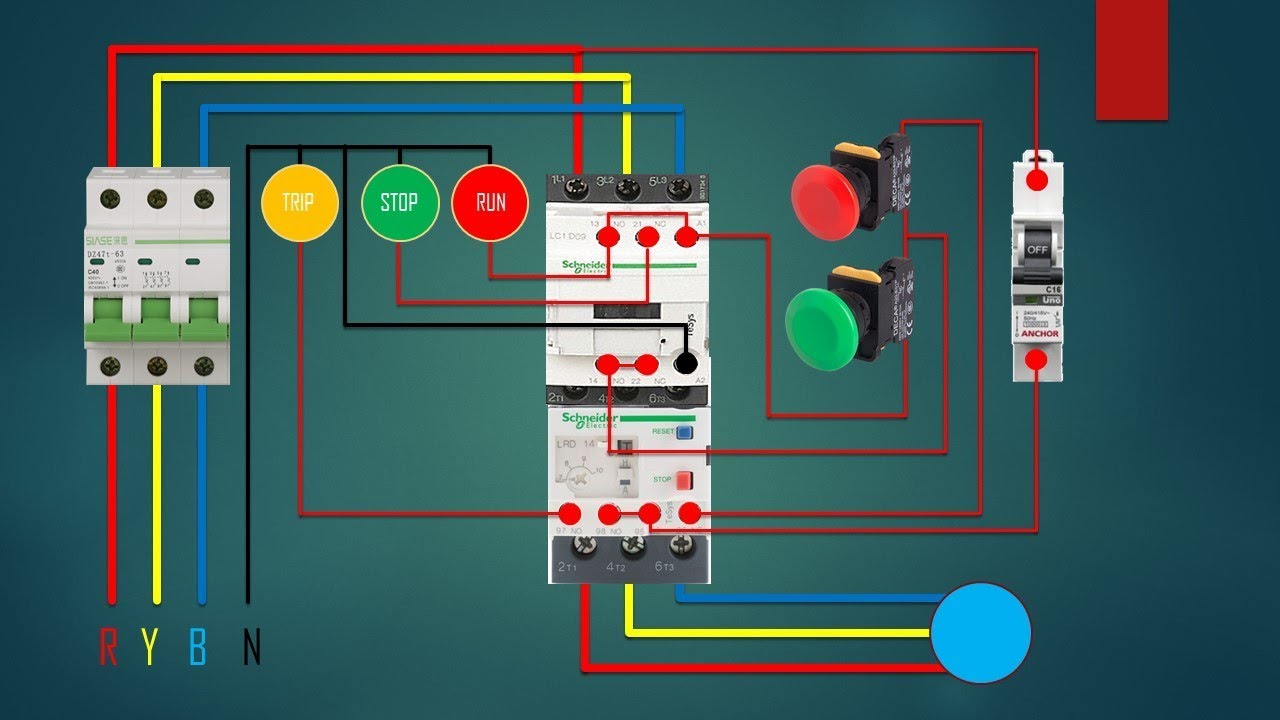
Before we dive into programming, it is important to understand the operation of the circuit above. Here are the key components and stages of operation:
- 3 Phase Circuit Overload - Each phase is protected by an overload that will trip as high current flows through due to a motor or circuit fault.
- Motor Contactor - The contactor acts as a bridge between the high voltage (motor) and low voltage (control (24VDC)) circuits. When the control circuit is energized, the power circuit is allowed to conduct the necessary current.
- Start Push Button - When pressed, the contactor is allowed to energize. The current flows through and the motor starts to operate.
- Stop Push Button - When pressed, the contactor is unlatched and stops conducting current which stops the motor.
Although the circuit is straightforward, there is one key feature: the momentary push buttons used for starting and stopping the motor latch in the contactor. In other words, once the momentary Start push button is pressed, the motor will continue to run until a Stop command is issued. In the industry, this is referred to as a latch circuit. This scheme is used in many applications including machinery starters, conveyors, process initiation and more.
The momentary push buttons are wired into digital inputs of a PLC. When either button is pressed, the appropriate input bits are set to HIGH (1). When the buttons are released, the same input bits are set to LOW (0).
The motor is tied to an output when set to HIGH (1), energizes the coil in the contactor and allows the current to flow.
Based on the above, we start by building a circuit that will run the motor when the Start push button is pressed.
The ladder logic above will take an input through an XIC instruction and energize an output over an OTE instruction. However, a major problem is the fact that the user must keep the button pressed for the motor to run. Typically, we'd want the motor to keep running after the button has been released. Let's look at the second iteration of our ladder logic circuit.
The second iteration of the ladder logic motor starter is able to start the motor and keep it running. However, we're now faced with another problem: there is no way to stop the motor.
The stop push button needs to be integrated into the logic. However, let's take a moment to understand the operation of this button. It has to have two functions:
- The stop push button should prevent the motor from getting started.
- The stop push button should stop the motor when it's running.
Based on the two requirements above, it's possible to add an XIO instruction into each branch of the circuit. However, ladder logic is such that the user can utilize a single instruction to cover both of those scenarios after the branch.
Example of a functionally sound rung based on the above requirements.
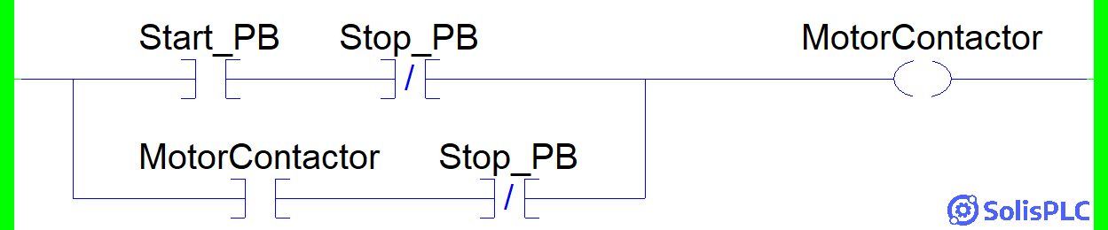
The rung above will operate as expected. However, it's important to create efficient ladder logic and utilize instructions in conjunction to the branch structures we've covered above.
The rung above operates as follows:
Stage 1 - The Start_PB is pressed and the MotorContactor is Energized while Stop_PB is not pressed.
Stage 2 - The MotorContactor bit is used to keep the motor energized while the Start_PB is released.
Stage 3 - The MotorContactor is de-energized when the Stop_PB is pressed.
The motor starter ladder logic example is easy to follow. However, as you expand your knowledge of ladder logic principles, you will create complex branches around similar circuits. It's not uncommon to have multiple stop conditions that are set in series with the "Stop_PB" bit. Similarly, it's common to see other sources of starting the motor. For example, a sequence may be used to start a specific pump through software.
Reading a Ladder Diagram
A Ladder Diagram is the representation of a circuit. It can differ in how it is drawn depending on the nature of the circuit, industry, and time it was drawn. We've seen a number of ladder logic examples above; a ladder diagram is used to represent the physical devices tied to the inputs and outputs in those software representations. In other words, a ladder logic diagram will contain an XIC (Examine if Closed) instruction that is tied to a physical push button; the ladder diagram will illustrate the contact of the push button.
Let's take a look at a few examples:
Ladder Diagram - Push Button & Lamp
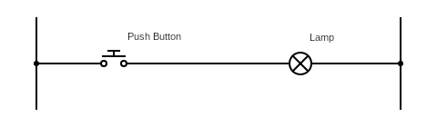
The most fundamental example of a ladder diagram involves a push button and a lamp. You can think of the push button as the switch in your room. When it is pressed, the lamp will turn ON. Note that in the previous examples of ladder logic found in the PLC, we've covered XIC and OTE instructions. In this example of a ladder diagram, you can think of the push button as the XIC instruction and the lamp as the OTE instruction.
Ladder Diagram - Motor Starter & Indicator
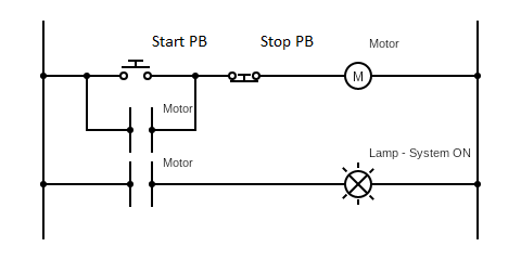
In the circuit diagram above, we've introduced a few new elements. In this scenario, we have a start push button, a stop push button, a motor, coils tied to the motor, and a lamp indicator. The operation of this ladder diagram is simple and has been covered in a few examples above. Once the start push button is pressed, the motor is energized. The first motor contact is used to check for the state and thus seals in the circuit. In other words, the momentary start push button allows the motor to run without needing to be pushed in. If the stop push button is pressed, the contact is broken and the motor is de-energized. The second level of the circuit illustrates a status light (typically green) that is enabled when the motor is running. This circuit is typical and notifies the operator of the state of a motor - pump, drive, etc.
Limit Switches and Ladder Logic Fundamentals
Limit switches are electromechanical devices that are used to detect the presence or absence of an object. They are commonly used in industrial automation to control machines and equipment. Limit switches are typically connected to a PLC (programmable logic controller), which is a computer that controls the machine or equipment. When a limit switch is activated, it sends a signal to the PLC. The PLC then executes the ladder logic program to determine what action to take. For example, a ladder logic program could be used to start a motor when a limit switch is activated, or to stop a motor when a limit switch is activated.
Here are some examples of how limit switches are used with PLC ladder logic:
- Conveyor belt control: A limit switch can be used to detect when a product reaches the end of a conveyor belt. The PLC can then use this information to stop the conveyor belt or to divert the product to another conveyor belt.
- Machine safety: Limit switches can be used to protect workers from injury. For example, a limit switch can be used to stop a machine if a worker's hand enters a dangerous area.
- Product counting: Limit switches can be used to count products as they move along a conveyor belt. The PLC can then use this information to track inventory or to control production.
- Machine sequencing: Limit switches can be used to sequence the operation of a machine. For example, a limit switch can be used to start a pump when a tank reaches a certain level, or to stop a conveyor belt when a product reaches a certain location.
Limit switches are a versatile and reliable way to control machines and equipment. By using limit switches with PLC ladder logic, engineers can create complex and sophisticated control systems.
.webp)
Ladder Diagram - Other
In modern electrical system designs, you'll often see ladder diagrams in industrial applications. This representation is easy to follow, lends itself to electrical equipment well, and is easily represented in software control systems - PLCs, DCS, SCADA, etc. However, you'll rarely find ladder diagrams to represent other electrical circuitry - Ex: embedded hardware. The reason is that these systems are difficult to illustrate in this manner and are rarely programmed through the same structure as PLCs.
Ladder Logic Q&A: Common Questions Answered
What is the concept of ladder logic?
Ladder logic is a graphical programming language used to develop control logic for Programmable Logic Controllers (PLCs). It visually represents electrical relay logic using rungs and symbols, making it easy for engineers and technicians with an electrical background to understand and implement automation logic.
What are the five basic rules of ladder logic?
- Power Flow – Logic flows from left to right, just like an electrical circuit.
- Contact Types – Ladder logic uses normally open (NO) and normally closed (NC) contacts to control the flow of signals.
- Coils and Outputs – Coils represent output devices such as motors, solenoids, or internal memory bits.
- Series and Parallel Logic – Logic operations can be arranged in series (AND logic) or parallel (OR logic).
- Scan Sequence – PLCs execute ladder logic in a cyclic scan, evaluating rungs sequentially from top to bottom.
What is the difference between ladder logic and PLC?
Ladder logic is a programming language, whereas a PLC (Programmable Logic Controller) is a hardware device that executes ladder logic programs. PLCs process input signals, run logic based on ladder diagrams, and control outputs in industrial automation.
What are the 5 PLC languages?
According to the IEC 61131-3 standard, the five main PLC programming languages are:
- Ladder Diagram (LD) – Graphical logic representation based on electrical relay circuits.
- Function Block Diagram (FBD) – Uses predefined function blocks to create logic.
- Structured Text (ST) – A high-level, text-based language similar to Pascal or C.
- Sequential Function Chart (SFC) – A flowchart-style language used for sequential processes.
- Instruction List (IL) – A low-level, assembly-like language (now deprecated in newer standards).
Do PLCs use Python?
Traditional PLCs do not natively support Python, as they primarily use IEC 61131-3 languages. However, modern edge computing devices, IIoT gateways, and soft PLCs (such as Codesys and Opto 22) increasingly support Python for data processing, analytics, and advanced automation tasks.
Is ladder logic still used?
Yes, ladder logic remains one of the most widely used PLC programming languages, especially in industries like manufacturing, automotive, food processing, and pharmaceuticals. Its simplicity and readability make it a preferred choice for machine control and automation.
Is PLC becoming obsolete?
PLCs are not becoming obsolete, but they are evolving. While traditional PLCs remain dominant in industrial automation, soft PLCs, industrial PCs (IPCs), and edge computing solutions are gaining traction due to their flexibility, connectivity, and ability to handle complex data processing.
How hard is ladder logic?
Ladder logic is considered one of the easiest PLC programming languages to learn, especially for those with an electrical or controls background. Its visual, relay-based approach makes it more intuitive than text-based programming languages. However, mastering advanced functions such as PID control, motion control, and structured programming requires experience.
What is PLC being replaced by?
While PLCs are still the backbone of industrial automation, soft PLCs, industrial PCs (IPCs), and cloud-based automation solutions are emerging alternatives. These newer technologies offer greater flexibility, scalability, and integration with modern IT systems, but traditional PLCs remain essential for high-reliability, real-time control applications.
Conclusion
Ladder Logic is the most common PLC Programming language. It's easy to learn, easy to use and has been adopted since the early days of Programmable Logic Controllers. The iconic resemblance to a ladder was what gave this type of logic its name. Such diagrams were used for specifying electrical drawings that were used in many industrial environments. Since those days, ladder logic has evolved significantly yet retains some of the basic elements: rails, rungs, input conditions, output instructions, comments, etc.
To learn ladder logic, you'll need to start with understanding current flow from the left rail to the right one. In summary, the current will attempt to flow through one rung at a time. As it encounters an input condition, it evaluates the result to TRUE or FALSE. If the condition is FALSE, the current will attempt to use a secondary path which may be through a circuit branch. If the result is TRUE, the current will proceed through the instruction. When it reaches an output instruction, it will execute the specified logic.
