Linking an Add On Instruction in RSLogix 5000 to a FactoryTalk Studio Faceplate Design

Introduction
PLC code is often written so that it is reusable. That means that one piece of code can be applied to any number of identical functions. In Allen Bradley PLC programming, this can be done through the use of Add On Instructions or AOIs.
When it comes to HMI design in FactoryTalk View Studio, Global Objects let you efficiently implement, reuse, and update common and repeatable elements in your projects.
Imagine you had 5 motors configured on a system and the function block or faceplate needed to be changed. Instead of having to update all 5 motors separately, the AOI or Global Object Faceplate can be modified and the changes will be propagated to all the motors. Mastering the use of Global Objects can greatly reduce your development time, and chance of errors.
In this tutorial, we’re going to design and execute an Add On Instruction in RSLogix 5000 and link it to a Faceplate in FactoryTalk View Studio.
Understanding Add On Instructions (AOIs)
An Add On Instruction or AOI allows you to generate a piece of code that can be reused throughout an entire project or multiple projects. Although the code within an AOI can be complex and have many rungs, it will be displayed as a function block showing only the critical parts, such as the inputs and outputs.
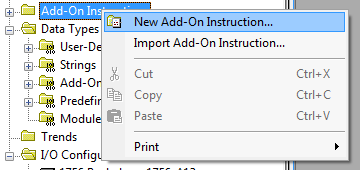
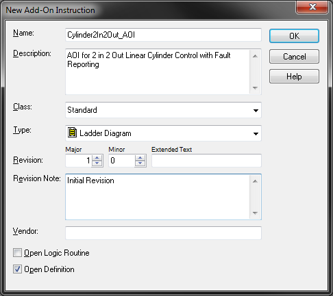
Creating the PLC code for the AOI
To demonstrate the design of an Add On Instruction, we’re going to create one - a simple 2 Input 2 Output Cylinder!
The two inputs in this case are the limit switches of our cylinder. The two outputs are the commands to the cylinder. When programming a cylinder we need to determine what action occurs when it is energized or de-energized. We usually call this “Extend” and “Retract”, but an action to extend a cylinder could be to move up, down, open, close, or anything else. This is why we define something standard like Extend and Retract, then we can assign our action to these.
When using a cylinder in a PLC project, it is safe to assume that it is not the only device being controlled. With that in mind, we consider different control modes by which it can be controlled. Almost certainly we will have an “Auto” mode and a “Manual” mode, but we could also have a “Datum” mode and a “Single Cycle” mode.
A Datum mode is useful in the case of hydraulic or air driven devices. When powered off the device will likely move from its ‘home’ position. Datum will move a device to a known safe position, ready for operation. In the case of our Cylinder, the Datum position could be extended or retracted.
A Single Cycle is useful for testing the operation of a device. Let’s imagine that in a machine automatic operation, a cylinder is extended, then 2 seconds later it is retracted. A Single Cycle will operate such that it will perform one full cycle of this, and then become idle again, waiting for another input from the operator.
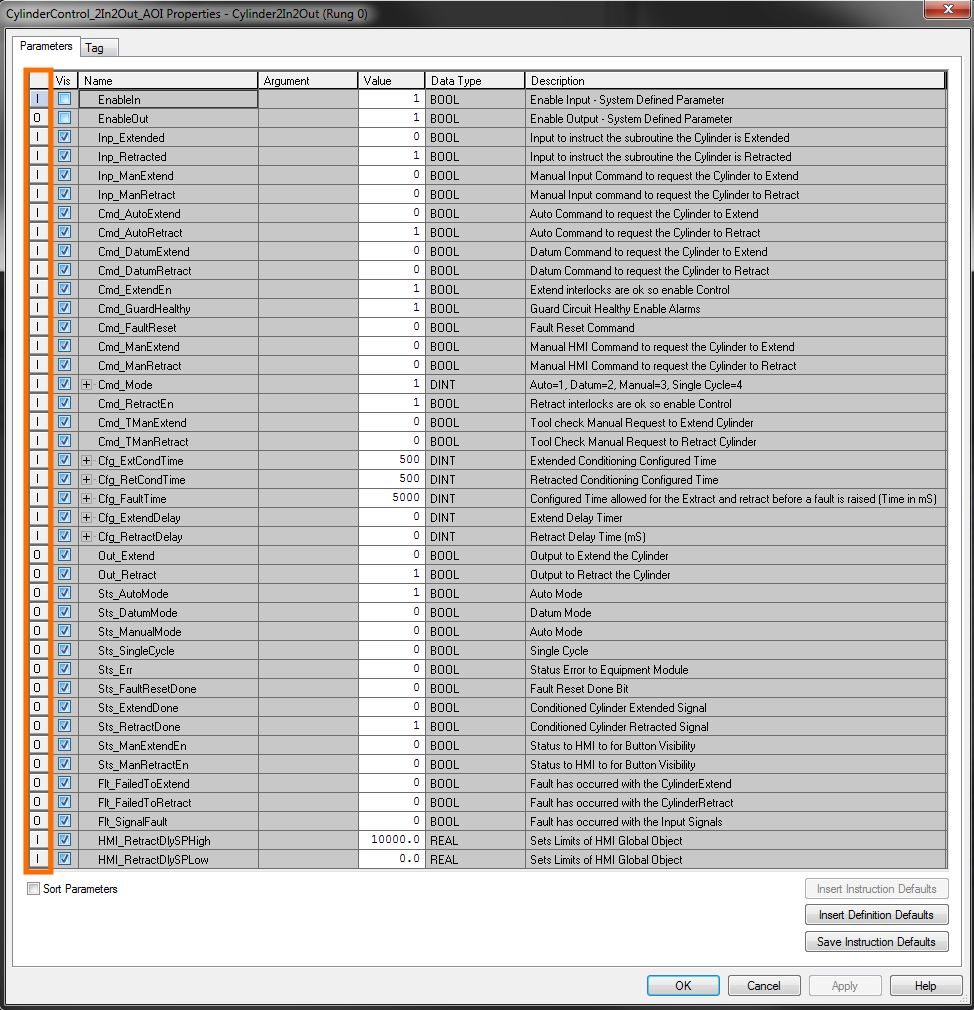
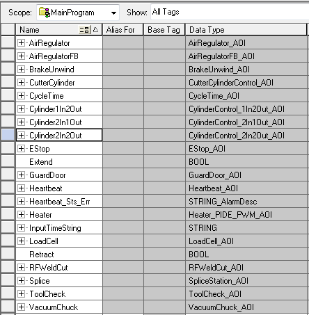
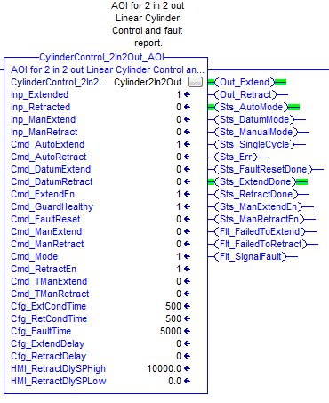
Our AOI needs some tags and logic to define its operation. The image below details all of the parameter tags captured in the “Cylinder2In2Out” AOI. Highlighted is the parameter Input/Output allocation. Inputs (I) will be shown on the AOI in the PLC code whereas Outputs (O) will not.
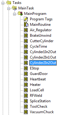
We can simply drag and drop the AOI onto a rung in the plc, in any specified routine. Remember to enable the routine using a ‘JSR’ in the ‘Main Routine’ block.
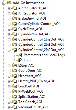
In the “Program Tags”, we create a new tag “Cylinder2In2Out” of data type “Cylinder2In2Out_AOI” (our newly created AOI) which we will use going forwards.
Now that we have written the code for the AOI in the PLC, we are ready to look at how to interface with the HMI.
Creating HMI Global Objects - Device
HMI Global Objects are useful because these objects can be parameterized. Once parameterized, all the user needs to do is add in unique information about the device such as its PLC tag address and the name of the device.
As mentioned above, a Cylinder will extend or retract, but that action can be to move up, down, in, out, open or close. We’ve kept it simple on the PLC side by using only the Extend and Retract labels, but when creating the HMI Global Objects, we want to be able to display the true action to the operator. To do this, we will add some text that can be parameterized to enable the buttons to display the true commands alongside the Extend and Retract text labels.
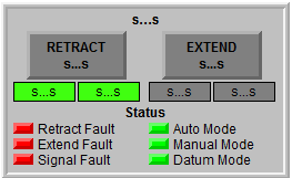
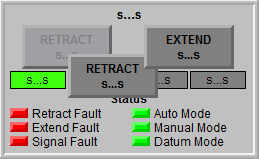
The Global Object above is an example of how we can create the layout of our 2 In 2 Out Cylinder device. All of the items on the Global Object displayed above are grouped so that we only need to enter the parameters once, and all the items in the group will use the definitions given.
This device is primarily used for the manual control of the device, so there will be other buttons to change the operation modes. Right-clicking on this Global Object allows us to set the Global Object Parameter Definitions.
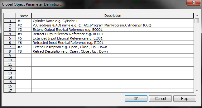
As shown above, the name of each parameter is listed along with a description of what the parameter is. This will help the user to complete this for each device. In this example the name is a # followed by a number, this is important, as these will be used on the global objects, not actual tags. Think of these as tag substitutions.
Now that we have defined each of these parameters, we can go ahead and tag up the buttons and indicators on the Global Object.
Selecting the “RETRACT” button and navigating to the “Connections” tab, the “Value” entered is “{#2.Cmd_ManRetract}”. Since the “#2” will give the full PLC address of the device, the Cmd_ManRetract links correctly to it so that when the button is pushed, the following tag is energized {::[AOI]Program:MainProgram.Cylinder2In2Out.Cmd_ManRetract}
Behind the “RETRACT” button is a placeholder that appears greyed out. This is so that when the device is not in Manual mode, we can set the visibility to hide the command button so that it cannot be energized if it is not in the correct mode.
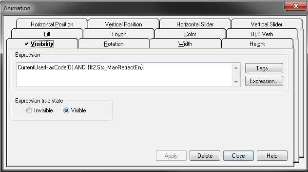
The expression used for the animation of the “RETRACT” HMI button allows us to include a User Code from “Runtime Security”, in this case, the user needs to have User Code (O) to be able to operate the buttons. In addition to the User Code requirement, “Sts_ManRetractEn” needs to be TRUE. This status is true when the device is in “Manual Mode”, indicated on the Global Object and when the device is NOT retracted i.e. it is EXTENDED. Note that the expression true state is selected to “Visible” meaning that the HMI button is displayed ONLY when these conditions are true.
The same is true for the “EXTEND” HMI button, except the “Value” entered is “{#2.Cmd_ManExtend}”.
Underneath the “EXTEND” and “RETRACT” HMI buttons, we have indicators to display the status of the Extended and Retracted inputs. These will be field connections that go into the PLC to verify its position. We also have indicators to display the Extend and Retract outputs. These outputs from the PLC will go to the field device, in our case to actuate the Cylinder.

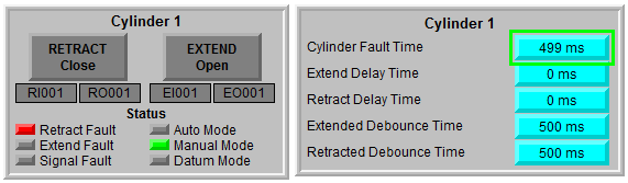
The final section of this Global Object is the Status indicators. To the left, we display the Status Faults, to the right the Control Mode Status. These will help the operator identify if something has gone wrong or whether the correct mode is selected.
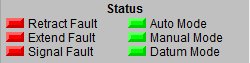
These indicators again link directly to the PLC via our “#2” parameter. The “Retract Fault” indicator therefore will be “{#2.Flt_FailedToRetract}” whilst the “Auto Mode” indicator will be “{#2.Sts_AutoMode}”.
Creating HMI Global Objects - Setpoints
Now that we have our device set up, we need to have another Global object so that we can enter our setpoints. We’ve parameterized these tags already in the PLC AOI, so following on from how we created the Global Object for the device, we can configure a Global Object for this too.
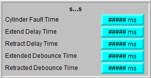
As shown above, we have 5 setpoints to assign. The numeric input field for “Cylinder Fault Time” needs the “Label” tab and the “Connections” tab filling in so that we can write to the correct tag (via “Connections”) and read the tag back to display to the user (via “Label”).
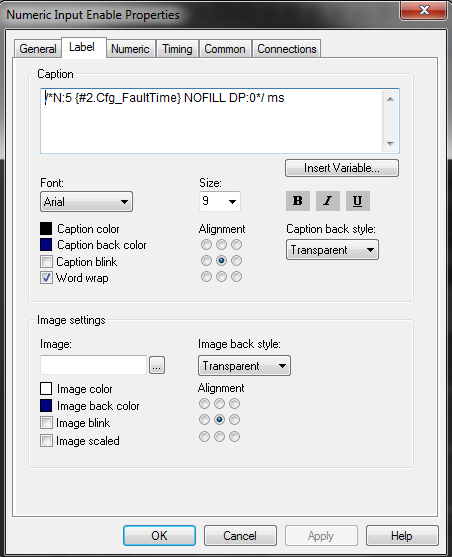
The “Label” tab caption should contain the following information;
/*N:5 {#2.Cfg_FaultTime} NOFILL DP:0*/ ms
Where;
‘N’ indicates that it is a numeric embedded variable
‘5’ indicates the number of digits
‘{#2.Cfg_FaultTime}’ specifies which numeric tag value to display
‘NOFILL’ is the fill character; NOFILL, ZEROFILL, or SPACEFILL
‘DP:0’ indicates the number of decimal places as 0
‘Ms’ is the units, milliseconds
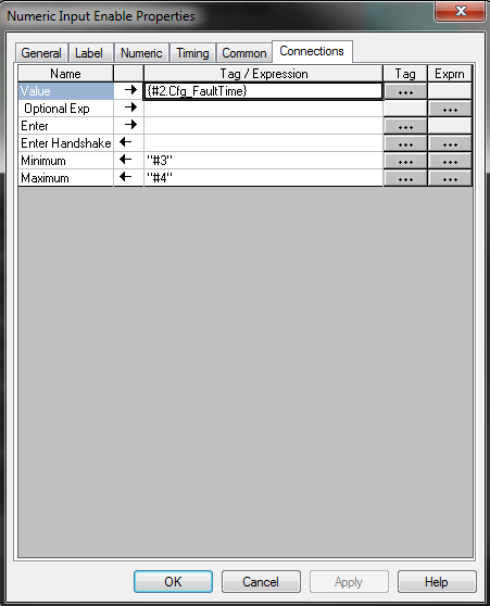
The “Connections” tab “Value” will be ‘{#2.Cfg_FaultTime}’ with the “Minimum” being ‘#3’ (Cylinder Fault Time Minimum Setpoint) and the “Maximum” being ‘#4’ (Cylinder Fault Time Maximum Setpoint).
The other setpoints can be completed in the same way.
Adding the Global Object to a Graphical Display
Now that we have completed the configuration of the Global Objects, it is time to add them to a Graphical Display!
Copy the two Global Objects to any Graphical display. From here, right-click the Global Object for the Device.
Previously, we selected ‘Global Object Parameter Definitions’ to define the parameters that the Global Object would use. This time we need to select ‘Global Object Parameter Values’.
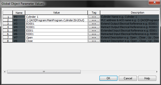
This window looks remarkably similar to the definitions window, of course, this time we have a space to add the value. In this example, we’ve defined it as follows;
#1 - Cylinder 1 (Name)
#2 - {::[AOI]Program:MainProgram.Cylinder2In2Out} (PLC Address)
#3 - EO001 (Extend Output Reference)
#4 - RO001 (Retract Output Reference)
#5 - EI001 (Extend Input Reference)
#6 - RI001 (Retract Input Reference)
#7 - Open (Extend Description)
#8 - Close (Retract Description)
Now right-click the Global Object for the Setpoints and select ‘Global Object Parameter Values’.
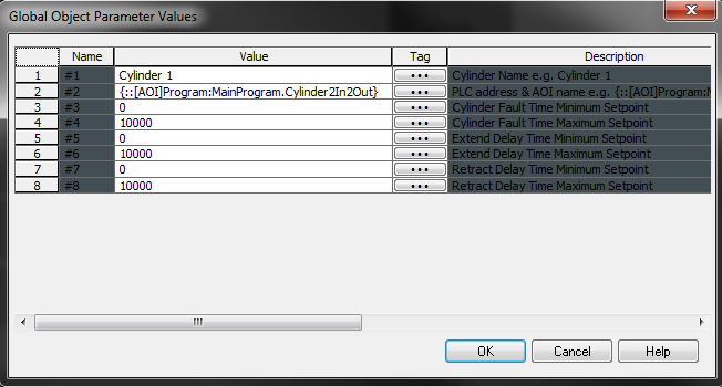
#1 - Cylinder 1 (Name)
#2 - {::[AOI]Program:MainProgram.Cylinder2In2Out} (PLC Address)
#3 - 0 (Cylinder Fault Time Minimum Setpoint)
#4 - 10000 (Cylinder Fault Time Maximum Setpoint)
#5 - 0 (Extend Delay Time Minimum Setpoint)
#6 - 10000 (Extend Delay Time Maximum Setpoint)
#7 - 0 (Retract Delay Time Minimum Setpoint)
#8 - 10000 (Retract Delay Time Maximum Setpoint)
For testing purposes, and in the absence of any actual inputs to give us our Inp_Retracted and Inp_Extended, the following code can be used in the PLC logic to simulate them;
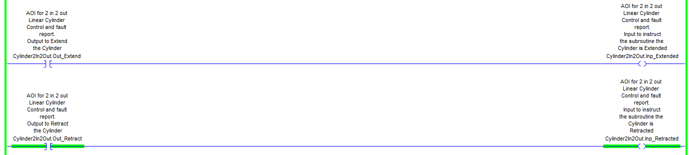
When we test this application, we want to make sure that we set the “Cmd_Mode” == 3 so we can test the device in manual mode.
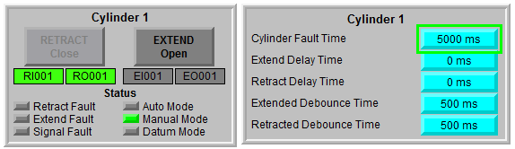
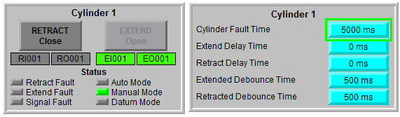
As shown above, the “RETRACT” HMI button is greyed out when the Cylinder is retracted, and the “EXTEND” HMI Button is greyed out when the Cylinder is extended.
If we set the “Cylinder Fault Time” to a value less than the “Extended/Retracted Debounce Time” we can generate a device fault. In this case, all outputs are turned off to protect the device and other plant equipment.
Conclusion
Mastering the use of Global Objects can greatly reduce your development time, and chance of errors. In this tutorial, we first learned how to create an Add On Instruction in RSLogix 5000, give it parameters and create a function that can be reused throughout the PLC program. We then learned about HMI Global Objects and how these can be created to link to the PLC objects by using Parameter Definitions.
We have explored how we could leverage AOIs and Global Objects to quickly add multiple Cylinders, and other devices, significantly reducing programming time. Finally, we have seen how changes made to Global Objects or AOIs, can be applied across all devices or objects that use them efficiently.
If you would like to learn more about HMI programming, make sure to check out this project where you’ll learn to build a simple batch processing system or this HMI Programming course that will teach you the basics of FactoryTalk View ME HMI development.
