Micro800 PLC Programming Getting Started

Introduction to Micro800 Programmable Logic Controllers
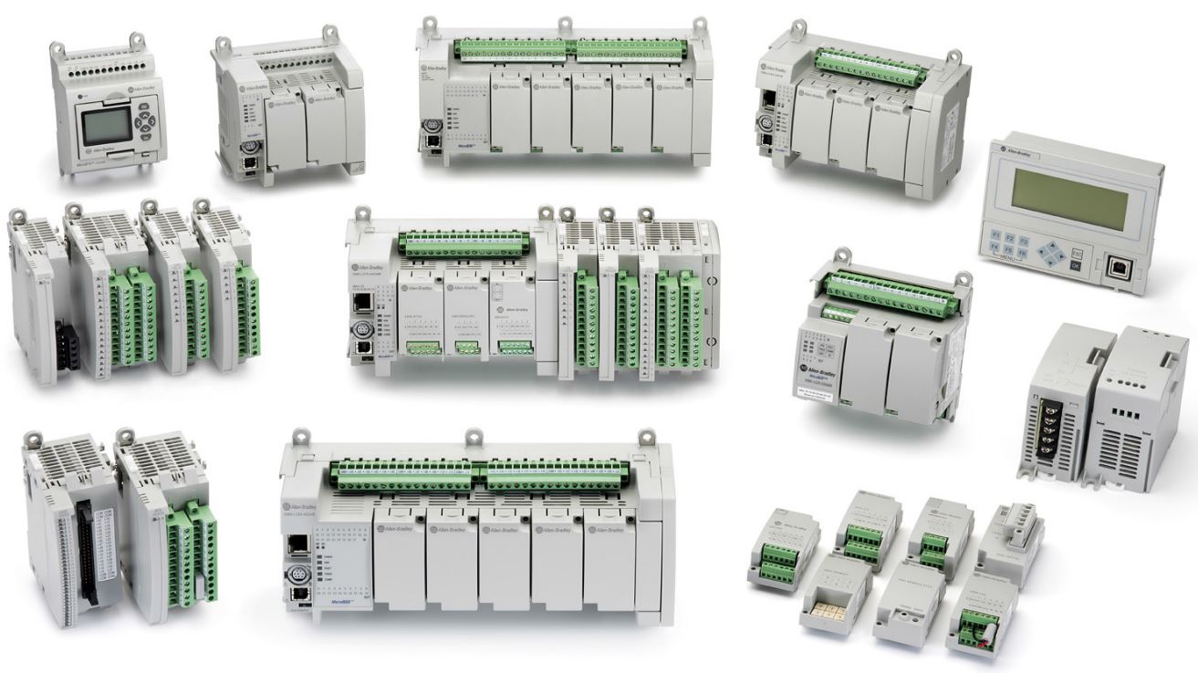
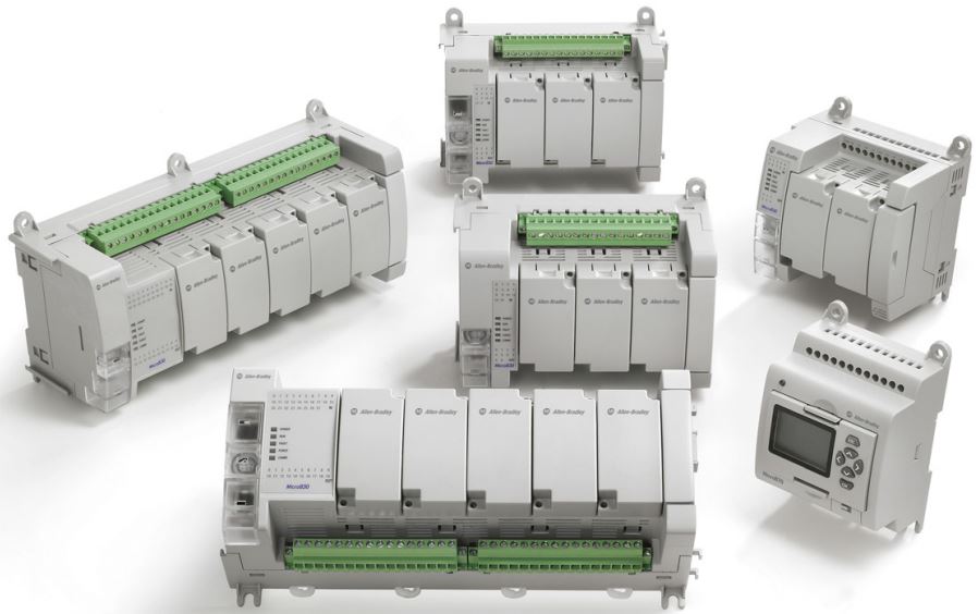
The Micro800 Control Systems by Rockwell Automation provide a cost effective solution for small to medium automation systems. The controllers within this family are typically used on stand alone machines or small process applications. The family offers five distinct controller types that are further customizable through add-on modules: Micro810, Micro820, Micro830, Micro850 and Micro870.
Unlike the other Rockwell Automation controllers, this line of PLCs is programmed through a dedicated software: Connected Components Workbench. From within this tool, the programmer can flash the firmware, load the program and monitor the state of the controller. Furthermore, Connected Components Workbench (CCW) is often used to program other non-PLC Rockwell Automation devices such as Variable Frequency Drives (VFDs) and certain Safety Relays.
In this tutorial, we will walk you through the process of getting started with a new Micro850 controller and PLC programming in the CCW environment. Note that the process will be similar with the other PLC types from the same family.
Advantages of the Micro800 PLC family
The cost savings realized through the use of a Micro800 PLC don’t stop at the hardware. Connected Components Workbench can be downloaded completely for free with minor restrictions.
In order to download your copy of CCW, follow the steps listed below:
Step 1 - Navigate to Rockwell Automation Download Centre.
Step 2 - Register for a free account.
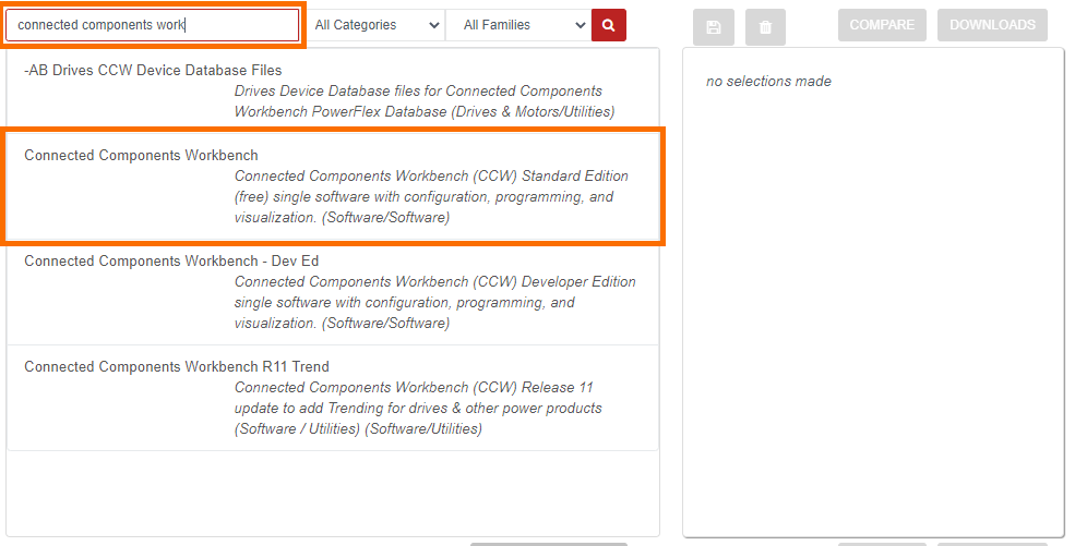
Step 3 - Search for “connected components workbench”.
Step 4 - Select “Connected Components Workbench” from the list of items
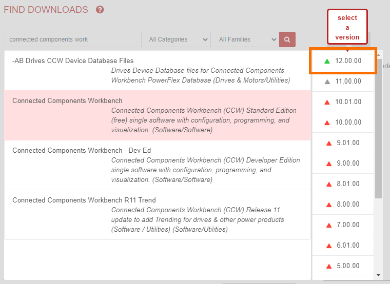
Step 5 - Choose a Software Revision (Note: we recommend the latest; v12.00.00 as of 7/23/2020)
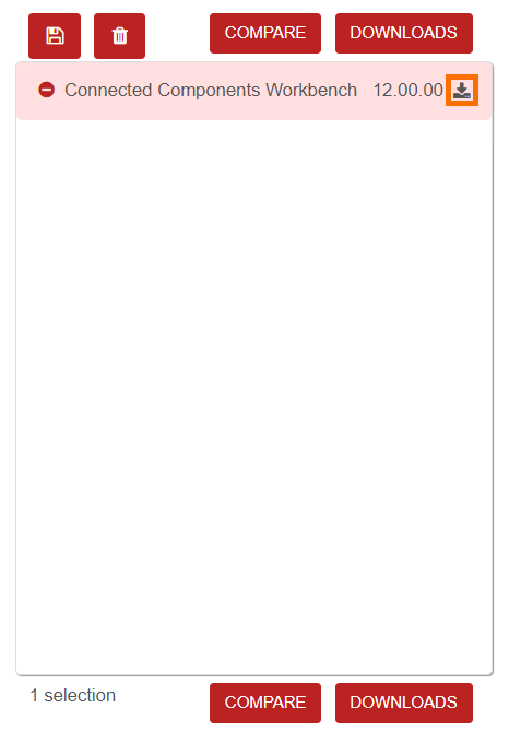
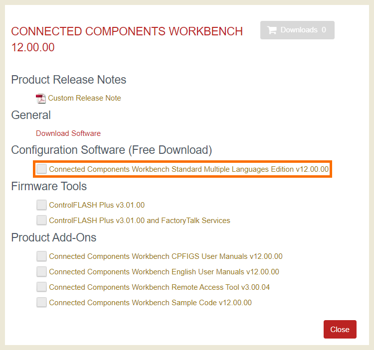
Step 6 - Press on the “Download” Icon on the left side of the window.
[Optional] Step 7 - Select “ControlFlash” if you plan on flashing the firmware of a Micro800 PLC.
Step 8 - Click on “Connected Components Workbench Standard Multiple Languages Edition v12.00.00” (Note: you won’t be able to download the free version by clicking on “Download Software”).
Step 9 - Accept the terms of service.
Step 10 - Download the Software (Note: we recommend using the “Managed Download” option).
Micro800 PLC Families Overview
As we mentioned above, the Micro800 family of PLCs is broken down further into five sub PLCs.
Micro810 PLCs
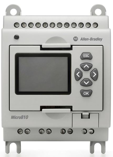
The Micro810 PLC is a nano-sized device suitable for small systems, motor starter systems, basic conveying applications and other simple processes. The user is offered four choices of PLCs within this family:
2080-LC10-12AWA
- 8 Digital 120-240VAC Inputs
- 4 Digital Relay Outputs
2080-LC10-12QWB
- 8 Digital 24VDC/VAC Inputs
- 4 Digital Relay Outputs
- 4 Analog 0-10VDC Inputs
2080-LC10-12DWD
- 8 Digital 12VDC Inputs
- 4 Digital Relay Outputs
- 4 Analog 0-10VDC Inputs
2080-LC10-12QBB
- 8 Digital 24VDC/VAC Inputs
- 4 Digital 24VDC Source Outputs
- 4 Analog 0-10VDC Inputs
Specialty Modules
The Micro810 PLC comes with an LCD module that can be used to configure certain features without the use of any other software tools.
Micro820 PLCs
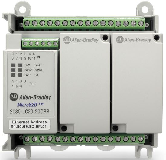
The Micro820 PLCs are designed to be suitable in small to medium sized machines. They come equipped with an EtherNet port that allows the PLC to communicate over the network to other devices. The Micro820 PLCs can be equipped with an add-on LCD module which allows configuration of certain parameters without the need of software. Here are the options for these PLC type:
2080-LC20-20AWB / 2080-LC20-20AWBR
- 8 Digital 120VAC Inputs
- 4 Digital 24VDC/VAC Inputs
- 7 Digital Relay Outputs
- 1 Analog 0-10VDC Output
- 4 Analog 0-10VDC Inputs
2080-LC20-20QWB / 2080-LC20-20QWBR
- 12 Digital 24VDC/VAC Inputs
- 7 Digital Relay Outputs
- 1 Analog 0-10VDC Output
- 4 Analog 0-10VDC Inputs
2080-LC20-20QBB / 2080-LC20-20QBBR
- 12 Digital 24VDC/VAC Inputs
- 7 Digital 24VDC Source Outputs
- 1 Analog 0-10VDC Output
- 4 Analog 0-10VDC Inputs
Specialty Modules
As mentioned above, an optional LCD screen can be purchased and installed on the Micro820 series PLC. Furthermore, Plug-in modules are available to extend the functionality of the controller. These modules will be covered in a section below.
Micro830 PLCs
The Micro830 PLCs differ from their Micro820 counterpart in the absence of the EtherNet port. The two options of programming and communicating with these PLCs are RS232 (Serial) and USB. Furthermore, the Micro830 series of PLCs are much more versatile and offer many more options to the user in terms of on-board I/O. The lineup of PLCs is as follows:
2080-LC30-10QWB
- 6 Digital 24VDC/VAC Inputs
- 4 Digital Relay Outputs
- 2 Embedded HSC Support
2080-LC30-10QVB
- 6 Digital 24VDC/VAC Inputs
- 4 Digital 24VDC Sink Outputs
- 2 Embedded HSC Support
2080-LC30-16AWB
- 10 Digital 120VAC Inputs
- 6 Digital Relay Outputs
2080-LC30-16QWB
- 10 Digital 24VDC/VAC Inputs
- 6 Digital Relay Outputs
- 2 Embedded HSC Support
2080-LC30-16QVB
- 10 Digital 24VDC/VAC Inputs
- 6 Digital 24VDC Sink Outputs
- 2 Embedded HSC Support
2080-LC30-24QWB
- 14 Digital 24VDC/VAC Inputs
- 10 Digital Relay Outputs
- 4 Embedded HSC Support
2080-LC30-24QVB
- 14 Digital 24VDC/VAC Inputs
- 10 Digital 24VDC Sink Outputs
- 4 Embedded HSC Support
2080-LC30-24QBB
- 14 Digital 24VDC/VAC Inputs
- 4 Embedded HSC Support
2080-LC30-48AWB
- 28 Digital 120VAC Inputs
- 20 Digital Relay Outputs
2080-LC30-48QWB
- 28 Digital 24VDC/VAC Inputs
- 20 Digital Relay Outputs
- 6 Embedded HSC Support
2080-LC30-48QVB
- 28 Digital 24VDC/VAC Inputs
- 20 Digital 24VDC Sink Outputs
- 6 Embedded HSC Support
2080-LC30-48QBB
- 28 Digital 24VDC/VAC Inputs
- 20 Digital 24VDC Source Outputs
- 6 Embedded HSC Support
Specialty Modules
The functionality of the Micro830 family can be extended through add-on modules covered below.
Micro850 PLCs
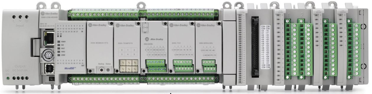
The Micro850 PLCs are suitable for medium machinery and processes. They can utilize on-board I/O as well as be extended through up to four external modules. Furthermore, this line of PLCs is capable of utilizing additional communication protocols unavailable to the modules listed above. These protocols include Modbus RTU, Modbus/TCP and CIP. The modules available for the user are as follows:
2080-LC50-24AWB
- 14 Digital 120VAC Inputs
- 10 Digital Relay Outputs
2080-LC50-24QWB
- 14 Digital 24VDC/VAC Inputs
- 10 Digital Relay Outputs
- 4 Imbedded HSC Support
2080-LC50-24QVB
- 14 Digital 24VDC/VAC Inputs
- 10 Digital 24VDC Sink Outputs
- 4 Embedded HSC Support
2080-LC50-24QBB
- 14 Digital 24VDC/VAC Inputs
- 10 Digital 24VDC Source Outputs
- 4 Embedded HSC Support
2080-LC50-48AWB
- 28 Digital 120VAC Inputs
- 20 Digital Relay Outputs
2080-LC50-48QWB
- 28 Digital 24VDC/VAC Inputs
- 20 Digital Relay Outputs
- 6 Embedded HSC Support
2080-LC50-48QVB
- 28 Digital 24VDC/VAC Inputs
- 20 Digital 24VDC Sink Outputs
- 6 Embedded HSC Support
2080-LC50-48QBB
- 28 Digital 24VDC/VAC Inputs
- 20 Digital 24VDC Source Outputs
- 6 Embedded HSC Support
Specialty Modules
The functionality of the Micro850 family can be extended through add-on modules as well as expansion modules covered below.
Micro870 PLCs
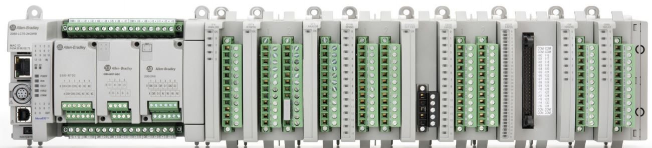
The Micro870 family of controllers is designed for larger standalone machine applications. These modules are fast, come equipped with multiple communication protocols and are able to control numerous devices over embedded I/O as well as EtherNet/IP and CIP motion. The external modules further extend the I/O of this specific controller with up to four modules (more modules can be added through the use of a power supply). Here is a list of available devices and their configuration:
2080-LC70-24AWB
- 14 Digital 120VAC Inputs
- 10 Digital Relay Outputs
2080-LC70-24QWB / 2080-LC70-24QWBK
- 14 Digital 24VDC/VAC Inputs
- 10 Digital Relay Outputs
- 4 Imbedded HSC Support
2080-LC70-24QBB / 2080-LC70-24QBBK
- 14 Digital 24VDC/VAC Inputs
- 10 Digital 24VDC Source Outputs
- 4 Imbedded HSC Support
Specialty Modules
The functionality of the Micro850 family can be extended through add-on modules as well as expansion modules covered below.
Micro800 Expansion I/O Modules
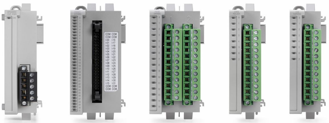
The Micro800 Expansion I/O modules can be attached to the Micro850 and Micro870 PLCs in order to extend the number of local inputs, outputs and/or communication ports. Here is a list of available modules and their features:
2085-IA8
- 8 Digital 120VAC Inputs
2085-IM8
- 8 Digital 240VAC Inputs
2085-OA8
- 8 Digital 120/240VAC Outputs
2085-IQ16
- 16 Digital 12/24VDC/VAC Sink/Source Inputs
2085-IQ32T
- 32 Digital 12/24VDC/VAC Sink/Source Inputs
2085-OV16
- 16 Digital 12/24VDC/VAC Sink Outputs
2085-OB16
- 16 Digital 12/24VDC/VAC Source Outputs
2085-OW8
- 8 Digital Relay Outputs
2085-OW16
- 16 Digital Relay Outputs
2085-IF4
- 4 Analog Voltage/Current Inputs
2085-IF8
- 8 Analog Voltage/Current Inputs
2085-OF4
- 4 Analog Voltage/Current Inputs
2085-IRT4
- 4 Analog RTD Inputs
2085-EP24VDC
- Power Supply for 4 additional modules
2085-ECR
- 2085 Bus Terminator
Micro800 Plug-In Modules
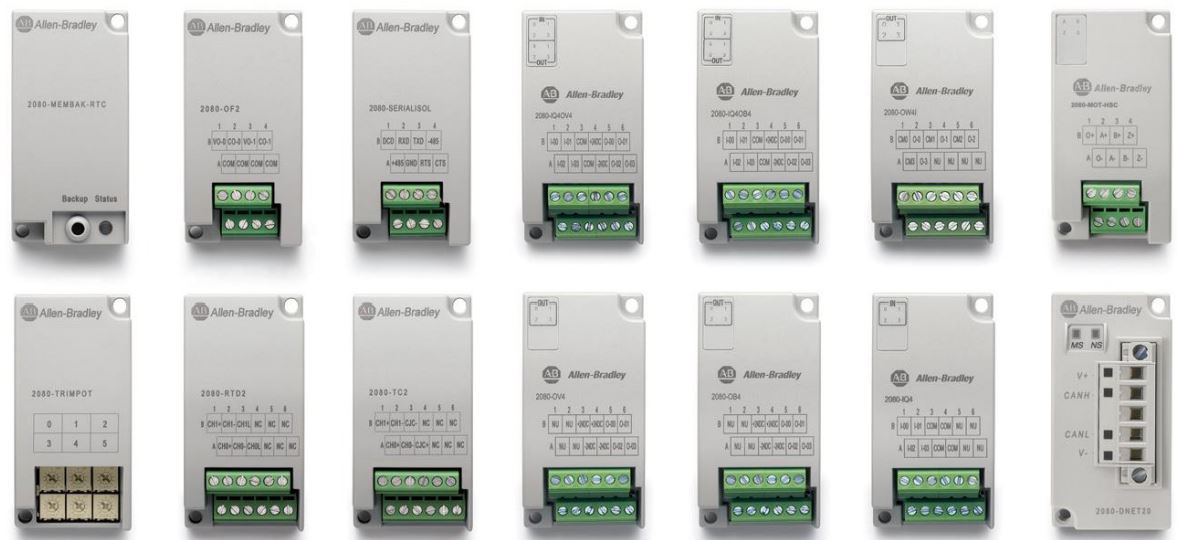
The Plug-In modules can be applied to the face of the Micro820, Micro830, Micro850 and Micro870 controllers. The number of plug-in modules depends on the controller size. They extend the functionality of the host controller by providing additional inputs, outputs and communication protocol slots. Note that the Micro850 and Micro870 PLCs can accommodate the plug-in modules as well as the expansion modules simultaneously.
Firmware Flashing the Micro800 Series
Just like any other Rockwell Automation controller, these PLCs ship with firmware revision 1.001. Therefore, the initial setup requires the user to flash the firmware before being able to connect and download a program.
Warning: based on our experience, it is possible to redned a Micro800 series PLC unusable by flashing the firmware over USB. We highly recommend that the user utilizes the host computer to flash and that the flash is performed directly from the computer to the PLC over EtherNet.
Using BOOTP to set an IP Address
Before you can flash the firmware, you must give the controller an IP address. Out of the box, the user will find the controller to have a BOOTP/DHCP address. To set an IP address, follow the process we’ve covered in the following tutorial: BOOTP IP Tutorial.
Micro850 PLC - 2080-LC50-24QWB
As mentioned above, we will be using a Micro850 PLC (Part Number 2080-LC50-24QWB) for the rest of the tutorial. Most other PLCs will be configured exactly the same way. However, the Micro830 series PLCs don’t offer the option to connect over EtherNet. Therefore, you will need to flash the firmware and connect to the PLC over USB or RS232.
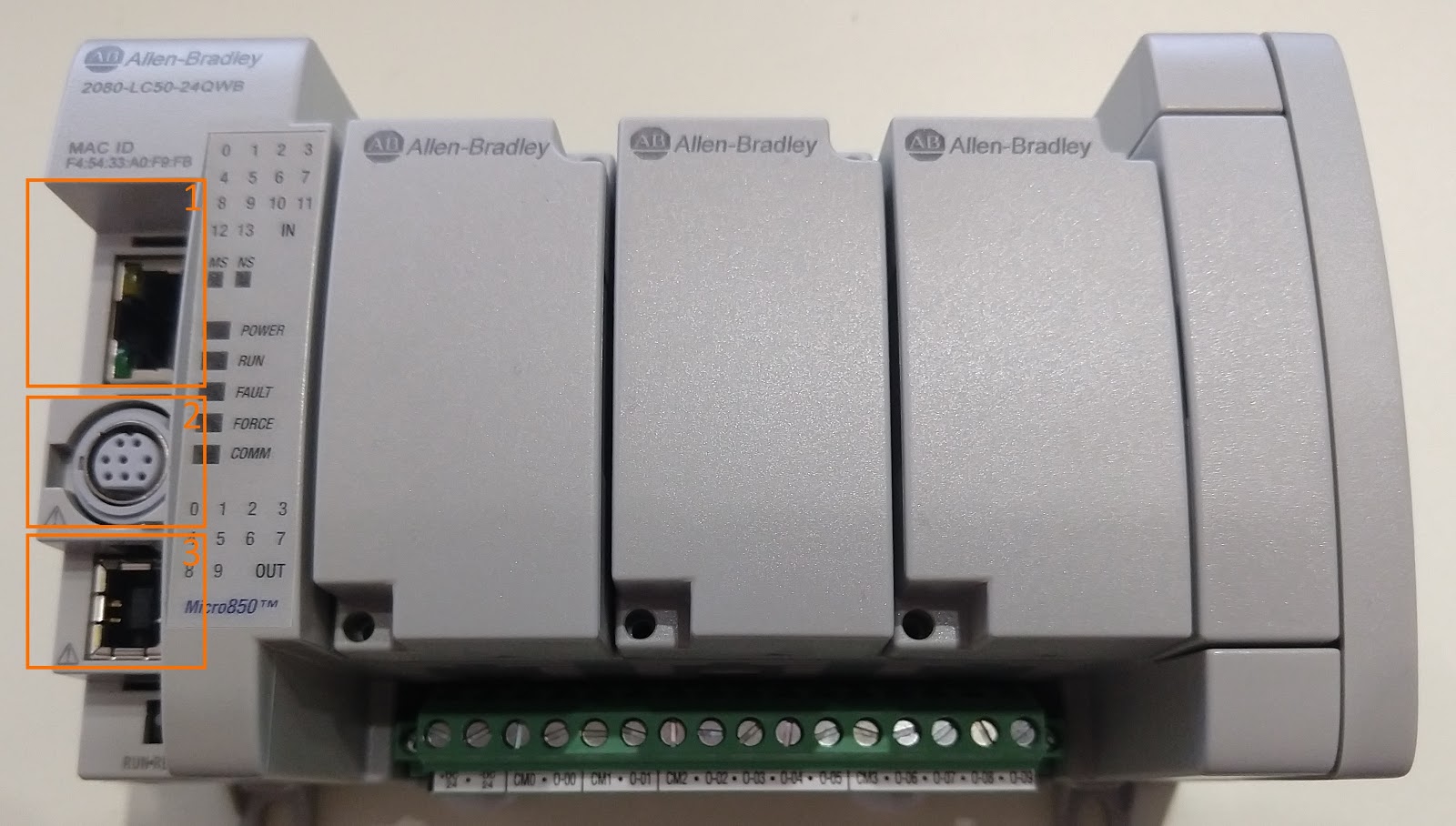
The Micro850 PLC comes with three ports as shown above.
Port 1 - EtherNet/IP
Port 2 - RS232 / RS485
Port 3 - USB type-B
For the purpose of this tutorial, we will be utilizing the EtherNet/IP port.
Connected Components Workbench New Project
Once we’ve installed Connected Components Workbench software and connected an EtherNet cable to the PLC, it’s time to create a project and go online with the controller.
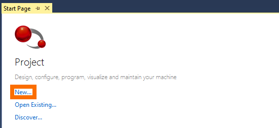
Step 1 - Create a new CCW project by clicking on “New”.
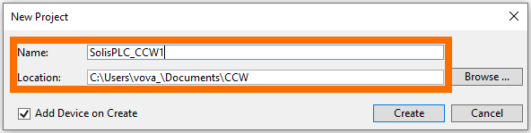
Step 2 - Give the project a name and set a location for the file. Click on “Create”.
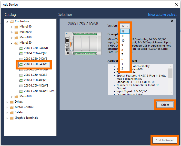
Step 3 - Select the Controller for the Project. Select the Firmware Revision of the Controller. Note 1 - In our case, the firmware revision is v12. Press on “Select”. Press on “Add to Project”.
Step 4 - Connect to the Controller. Press on the “Disconnected” button. Browse to the controller in RSLinx and select the module. Press on the “OK” button.
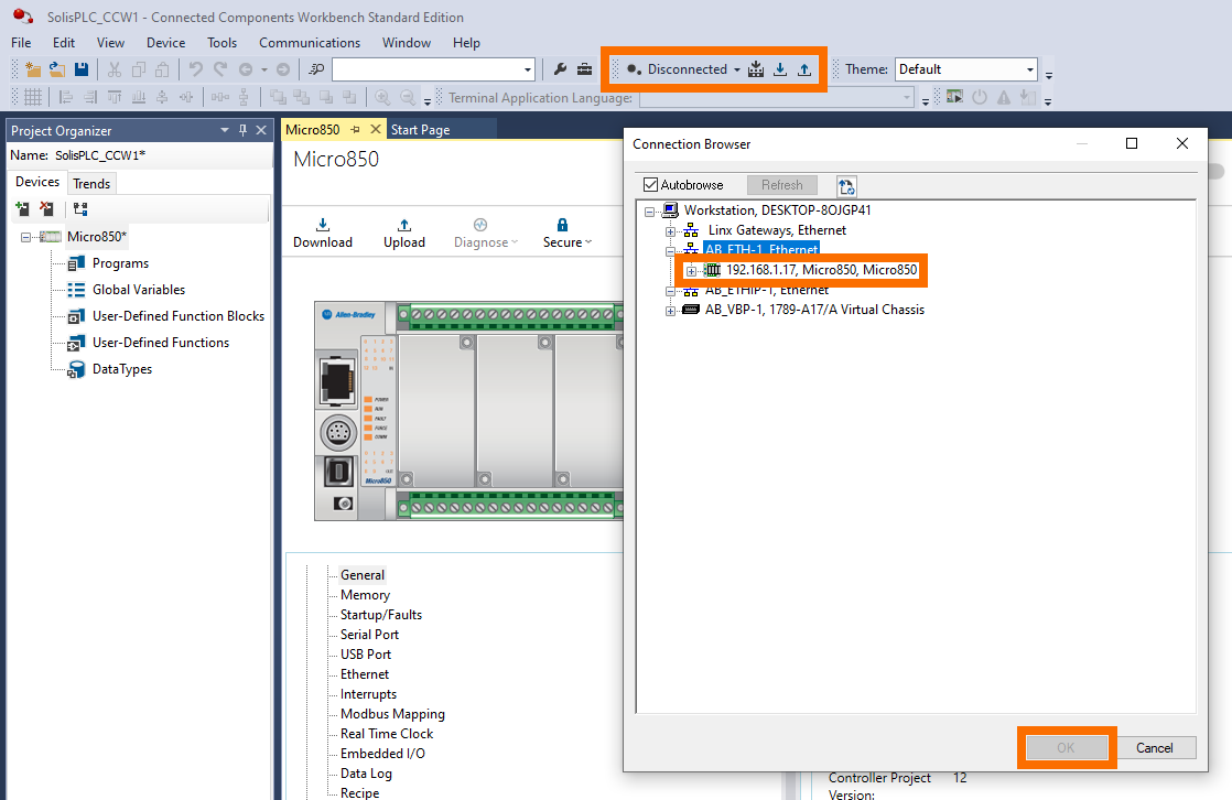
Note that at this point, you will receive a prompt that will allow you to download the current program to the controller or upload the one on the controller to your computer. Since we’re working with a new controller, we’ve downloaded the project to the controller. If you’re working with a controller that has a program, we recommend backing it up by using an upload. The process of downloading is irreversible and will erase the current program.
Connecting to the controller is the first step in every project. If the connection has been established successfully, the following status will be displayed in CCW:
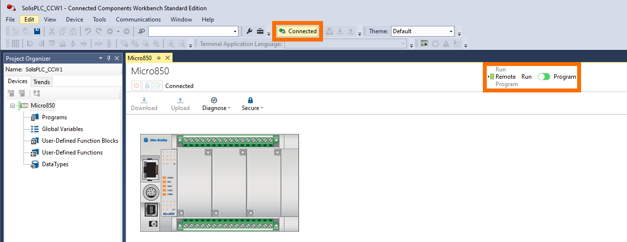
Although we always connect to the controller at the start of the project, if you’re familiar with Studio 5000, you’ll be somewhat disappointed. It is not possible to make changes to the hardware or software while online with the controller through CCW. These controllers are highly flexible, but the user must disconnect in order to make changes to the program or the modules connected to the PLC.
Adding Plug-In and Expansion Modules
Disconnect from the controller and you will be able to add plug-in and expansion modules to your Micro800 controller.
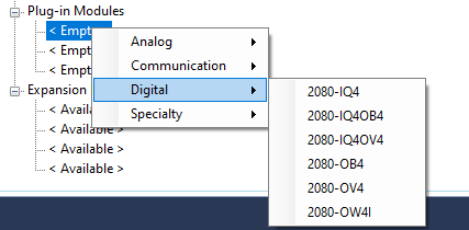
By right-clicking an <Empty> or <Available> slot, the user can select an appropriate module to be added to the configuration of the controller. Note that since the program is offline, the controller will allow you to add any module without a validation; an error will be thrown once you go online.
Writing a Simple Ladder Logic Program
Now that we’ve established communication to the controller, it’s time to write a simple that will turn ON and OFF an output. the Micro800 series PLCs can be programmed in Structured Text, Ladder Logic and Function Block Diagrams. Although we recommend that every PLC programmer becomes familiar with each language, we will illustrate a simple example in ladder logic below.
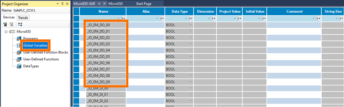
The Inputs and Outputs of the Micro500 PLC are found under the “Global Variables” in CCW. In this table, the user will find the 10 digital outputs and 14 digital inputs available on this specific controller. Our goal is to cycle through an output every second.
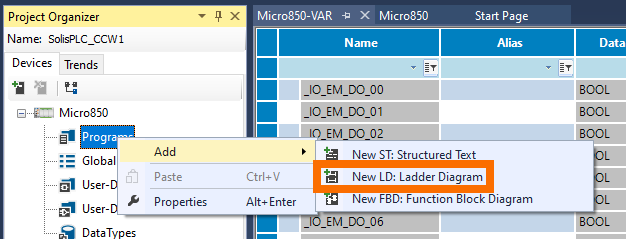
Create a new ladder diagram program by clicking on “Programs”, “Add” and “New LD: Ladder diagram”.
Create the following ladder logic diagram:
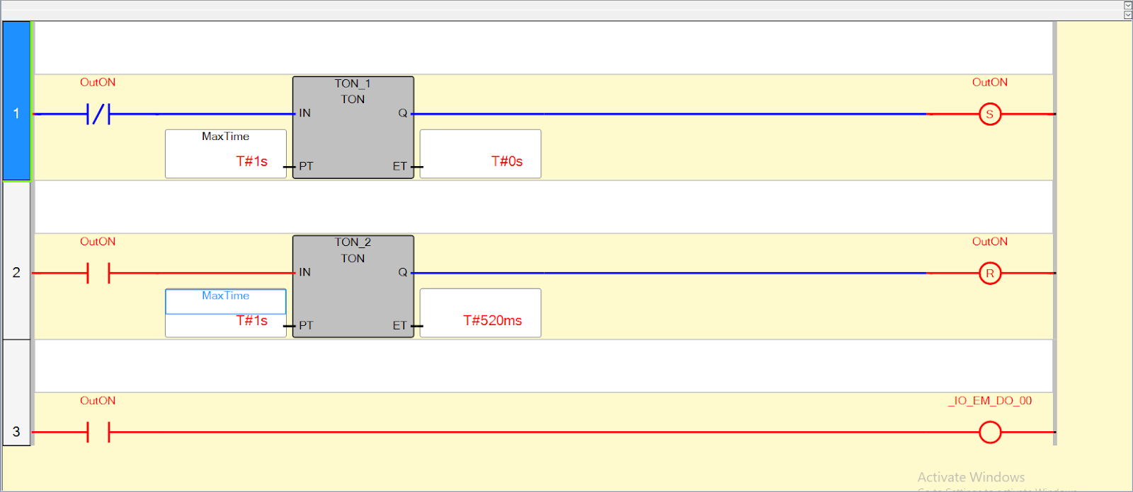
Note that the above diagram will set the OutON for one second and reset the same for one second. Based on the status of this bit, we will energize the first output of the PLC: _IO_EM_DO_00. In our case, this is a relay based digital output.
Conclusion
The Micro800 series of PLCs from Rockwell Automation offer a cost effective solution for small to medium applications. The family of PLCs contains five distinct sub-families: Micro810, Micro820, Micro830, Micro850 and Micro870. Each family offers a unique feature that may impact the price as well as the features provided by the platform.
All the Micro800 PLCs are programmed using Connected Components Workbench. CCW is a free tool that can be downloaded directly from the Rockwell Automation website. The low cost of development makes these PLCs particularly useful for small projects and learning PLC programming.
