Open User Communication in Siemens TIA Portal

Introduction
Communication between PLCs and multiple devices is one of the major components of the modern industry. Many solutions are available to communicate between different parts, from analog transmissions such as the 4-20 mA standard to the digital Fieldbuses and networks. Each solution offers its advantages and disadvantages, but the use of Fieldbuses is currently the most widespread.
Siemens used to inherently support the Profibus protocol, which has been replaced with the Profinet protocol. Based on the Industrial Ethernet protocol, Profinet allows reliable real-time communication. It can be interfaced with any Ethernet network without specific hardware and communicate with any device supporting TCP, ISO/TCP, and UDP.
In this tutorial, you’ll learn how to configure a Profinet communication between an S7-1500 PLC and any unspecified Ethernet device in Siemens TIA Portal. The steps outlined in this tutorial will apply to any equipment you want to communicate with during your projects.
Prerequisites
To follow along with this tutorial, you will need an installation of TIA Portal. We will be using TIA Portal v17, but you can use any other version. No additional hardware or software is required.
Using the Compact OUC instructions in TIA Portal
This part will demonstrate the simplest way to establish Profinet communication. Typically, this would require establishing a connection, sending or receiving data, then closing the connection. However, Siemens offers instructions that combine these three steps into Compact instructions: Tsend_c and Trcv_c.
Let’s start by creating a project with two S7-1500 PLCs. One will be the actual PLC we want to communicate with; the second will play the role of the field device. It could be anything such as a PC, a sensor, a VFD, or any equipment that speaks TCP, ISO/TCP, or UDP protocols.
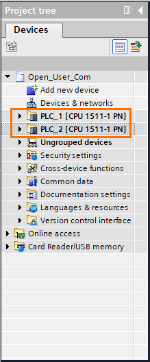
Since we are on an EtherNet connection, one of the two PLCs will be the client and the other the server. For our tutorial, PLC_2 will act as the server and PLC_1 as the client.
For the connection to be successful, the server must open its port and wait for the client's request. Therefore, we’ll start programming the second PLC to avoid any errors we may encounter.
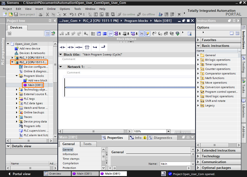
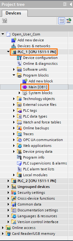
Open the PLC_2 folder in the project tree and open the main program OB1.
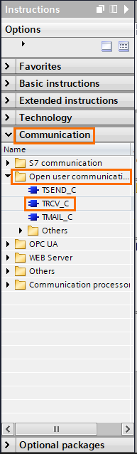
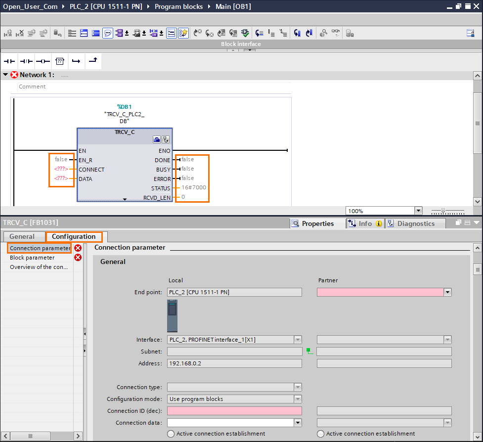
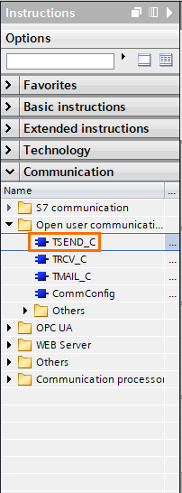
On the left side of the screen, you can find the “Instructions” window. First, open the “Communication” tab, then the “Open user communication,” and drag-and-drop a “TRCV_C” instruction.
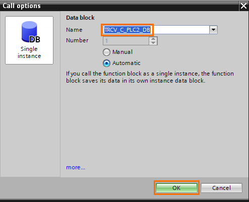
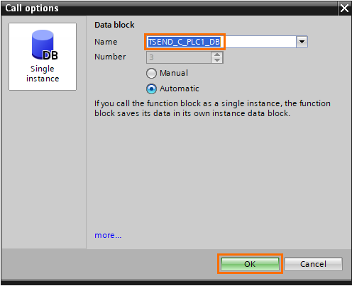
A “Call options” window will appear upon dropping the instruction, asking you to create a data block containing all the instruction data. Give a name of your choice to this DB and click on “OK.”
The TRCV_C instruction (The C stands for Compact) establishes the connection, receives data, then closes the connection all in one instruction.
Its inputs are
- EN_R: Is the enabler input of the instruction. It can be any boolean or clock that will trigger the instruction when detecting a rising edge.
- CONNECT: This is a data block that contains the connection parameters. This block will be automatically created during the connection configuration later.
- DATA: This is the data area where the received data will be written.
For the outputs
- DONE: This is a boolean that will turn to 1 after the instruction is successful.
- BUSY: This is a boolean that turns to 1 during the communication.
- ERROR: This is a boolean that will turn to 1 in case of communication failure.
- STATUS: This is a word that contains a hex code that represents the actual state of the communication. You can find the meaning of each code in the TIA Portal help by pressing F1.
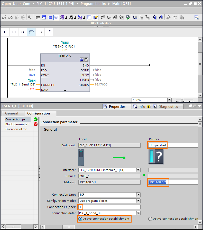
Let’s start configuring the instruction. First, select the instruction, then, in the parameter window below, open the “Configuration” tab, then click on “Connection parameters.”
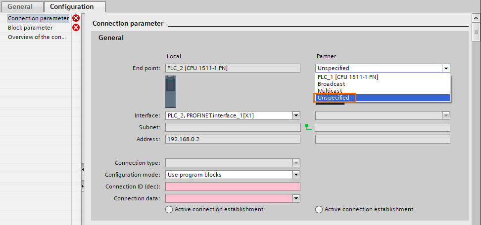
We must first designate a connection partner. Click on the “Partner” scroll. It’ll contain four options.
- PLC_1: Since there’s already another PLC in the project, the system automatically proposes it as a potential partner.
- Broadcast: This means that the instruction will try to connect to all available partners in the network.
- Multicast: This is used to connect to multiple specific partners.
- Unspecified: This is used to connect to one unspecified partner just by knowing its IP address.
Since we are demonstrating how to connect to any type of device, we will use the “Unspecified” option.
Then, we have to create a connection data block. Open the “Connection Data” scroll and click on “New”.
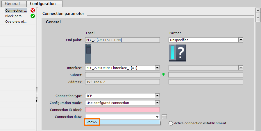
The data block is automatically created. Now we have to configure it.
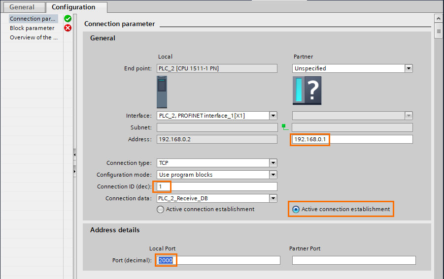
First, we have to give the device's IP address we want to connect with. For example, the IP address of the PLC_1 is set at {192.168.0.1}.
You can change the connection type from TCP to ISO/TCP or UDP but we will keep it like that since TCP is the most common protocol.
After that, you have to set an ID for the connection. It can be any decimal value. Just keep it in mind because we will need it later.
I’d like to bring your attention to the “Active connection establishment” option. This is an option can be activated only in one of the two partners. It tells which of the partners will try to actively establish the connection.
In our case, the Client is PLC_1 and the server is PLC_2. So the “Active connection establishment” must be activated on the side of the partner. We must select the port that will be opened in PLC_2. By default, it’s the port 2000.
Now the configuration is done, we can set the other instruction parameters.
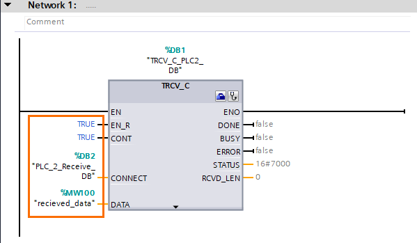
For the EN_R input, you can use any trigger you want, but since we are n the server-side, it is easier to keep the input at a constant TRUE. This way, the server’s port will always be open and listening.
The CONNECT input has been automatically created with the configuration we did earlier.
You can put any memory area in the DATA input; I set a word tagged “received_data” at MW100.
You can also notice a new input named CONT with a constant TRUE. This defines when the connection must be closed. If TRUE, the instruction won’t disconnect et wait for more data. If FALSE, the instruction will disconnect after receiving data.
You don’t have to put anything in the ouputs for the instruction to work. These are used to monitor the state of the connection. You can use them in your programs to detect failures for example.
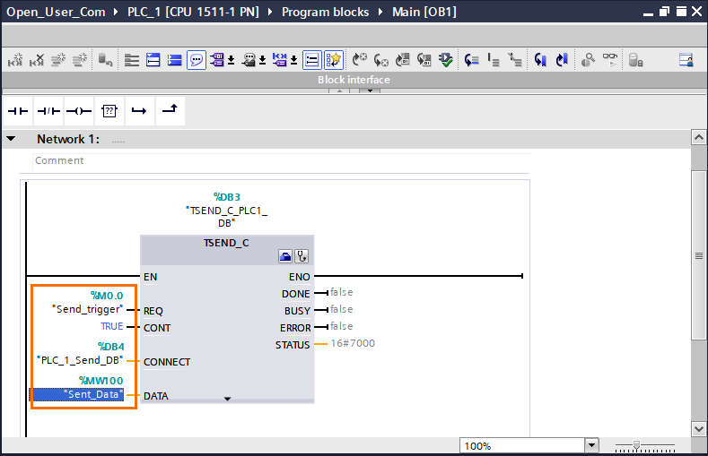
We are now done with the PLC_2 side. Let’s go to the PLC_1 side now. First, open the main program (OB1) of PLC_1 in the project tree.
The following steps will be similar to what we just did with PLC_2. This time we use a TSEND_C Instruction.
Like before, a “Call options” window will appear. Give a name and click on “OK”.
Repeat the same connection configuration with TRCV_C (Partner and Connection Data). But this time, set the address of PLC_2 {192.168.0.2}. Use the same Connection ID we used for TRC_C (1) and select PLC_1 as the “Active connection establishment” since it’s the Client.
The same goes for the instruction parameters. The only difference is we are using a memory bit at M0.0 tagged “Send_trigger” for the EN_R input to initiate the communication.
And that’s it. We’re done. By following the steps above, you can communicate with any type of device that supports Profinet or Ethernet.
But using these compact instructions can have its limits. Since the Ethernet is an asynchronous protocol (and Profinet is based on Ethernet), we may be subject to some communication errors in some cases.
To prevent this, we must use the compact instructions' decomposed form, elementary Open User Communication instructions.
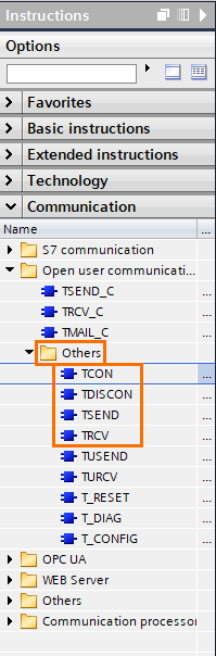
Using the elementary OUC instructions in TIA Portal
If we look closely at the compact instructions, they are, in fact, the combination of three simpler instructions: TCON (Connect), TSEND/TRCV (Send/Receive), and TDISCON (Disconnect). For example, you can replicate a TSEND_C instruction by using TCON, TSEND and TDISCON together.
Being able to control each instruction individually offers better control over the communication process and allows the development of more complex and effective programs.
You can find these instructions by opening the “Others” folder in the “Open User Communication” instructions.
For example, we will replicate what we did in the first part but use elementary instructions instead of compact ones.
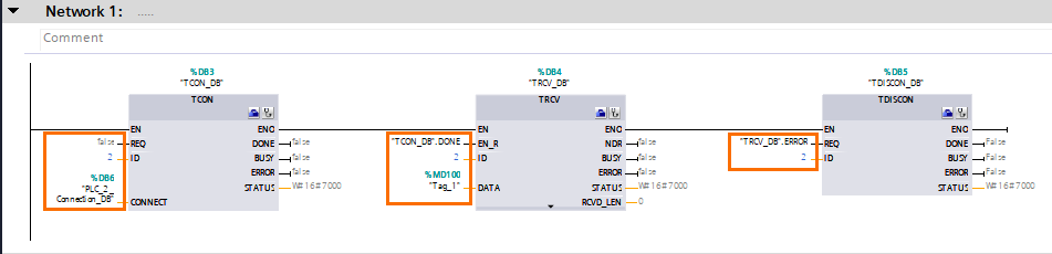
Open the main program of the PLC_2 and drag and drop each TCON, TRCV, and TDISCON. Creating a DB whenever it’s asked.
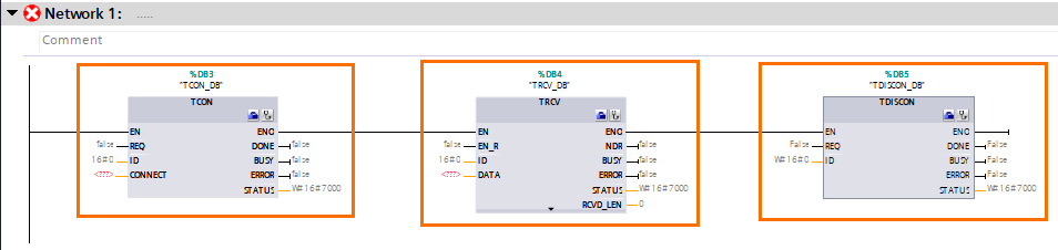
TCON must be configured the same way we did for TRCV_C in PLC_2. You’ll only need to remember the connection ID to use it in TRCV and TDISCON.
You can fill the parameters of the instructions as shown in the next figure (The Connection ID has been set to 2).
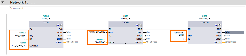
Repeat the same steps for PLC_1 but use TSEND instead. After configuring and filling the parameters, you should have the same result as shown in the next figure.
Use these instructions for large networks and complexe trafics to have a full control over each communication.
Conclusion
This tutorial taught you how to configure a Profinet communication within the Siemens environment properly.
Using compact instructions can significantly simplify the communication programming, but it can show some inconsistencies due to the asynchronous nature of the protocol. Therefore, its best use is for punctual communications to quickly read or write data.
But in the case of more complex and more extensive networks, it is preferable to use the elementary instructions to have complete control over your traffic. To carefully connect and disconnect each connection in the right moments and prevent communication errors.
