Configuring Modbus TCP Communications in Siemens TIA Portal

Introduction
In factory automation, there exists a number of industrial protocols used for communication and transmitting data. One such protocol is the Modbus TCP. Modbus TCP is a very simple-to-understand and easy-to-implement industrial protocol.
In this tutorial we'll cover how to configure a Siemens S71500 PLC as both a Modbus Client and Modbus server, we will learn how to read and write data over the Modbus network, and how to use PLCSIM Advanced for advanced simulation functions in TIA Portal.
If this is the first time you are coming across the Modbus protocol, you should first read this introductory tutorial.
Prerequisites
In order to follow along with this tutorial, you will need:
- An installation of Tia Portal. In this tutorial, we will be using Tia Portal V16.
- An installation of PLCSIM Advanced- V4.0.
- An installation of Modbus Poll (a simulation software that serves as a Modbus client)
- An installation of Modbus Slave (a simulation software that serves as a Modbus server)
Setting up a new project in Tia Portal
Let us start by creating a new project

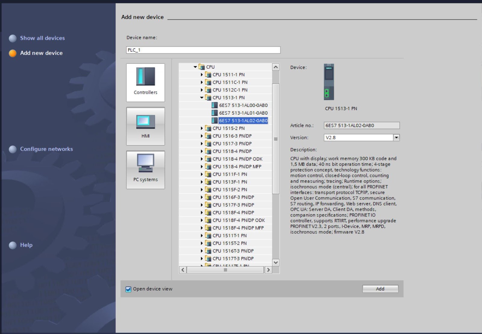
Once it is opened, add a new device. Here we have chosen the part number 6ES7 513-1AL02-0AB0
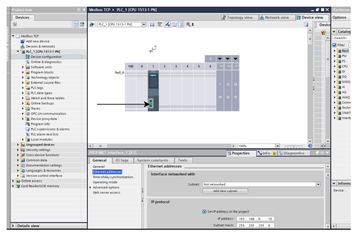
Next, we set the ethernet address of the PLC to be 192.168.0.10 by double-clicking on the ethernet port.
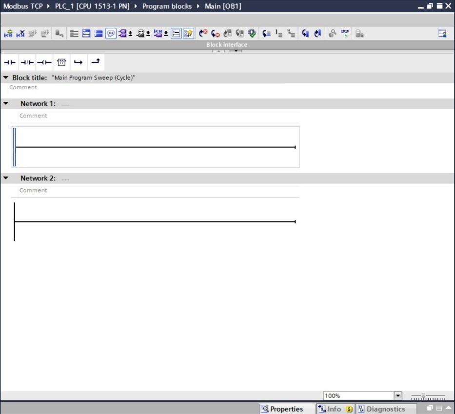
Opening Program blocks and navigating to OB1 (Main) takes us to the programming area.
Configuring the Modbus server
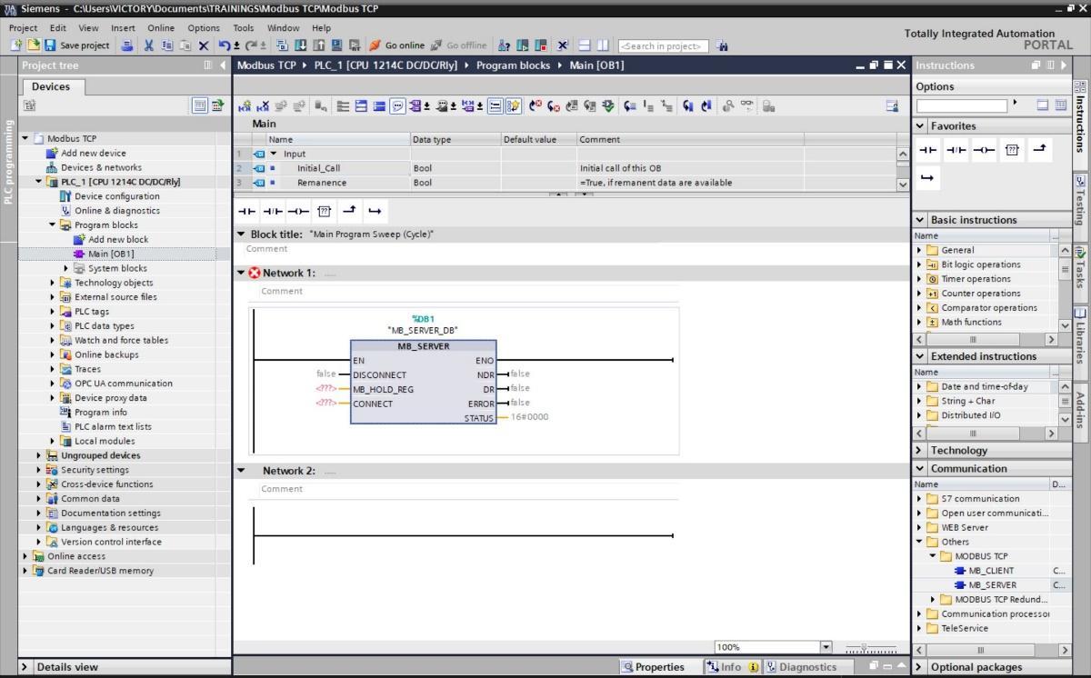
Under the communications tab, click others. Select Modbus TCP and pick MB_SERVER.
When a call option dialog box prompts select “OK”.

The programming area should look like this.
This is a description of the parameters
DISCONNECT - With this parameter, you control the establishment and termination of the connection to the Modbus server.
MB_HOLD_REG – This is a pointer to the Modbus holding register of the "MB_SERVER" instruction. This is a data block that contains the holding registers that will be accessed by a Modbus client using the Modbus functions.
CONNECT – This is a pointer to the structure of the connection description. The parameter has the data type TCON_IPV4; this Includes all address parameters that are required for establishing a programmed connection in Siemens. The default address is 0.0.0.0 (any IP address), but you can enter a specific IP address so that the server only responds to requests from this address.
NDR – New Data Ready. 0 no new data and 1 new data written by the Modbus client.
DR – Data Read. 0: No data read and 1: Data read by the Modbus client
ERROR – If an error occurs during the call of the "MB_SERVER" instruction, the output of the ERROR parameter is set to "1". Detailed information about the cause of the problem is indicated by the STATUS parameter.
STATUS - Detailed status information of the instruction.
Create a new Data Block that will contain the Modbus configuration parameters and configure it as follows.
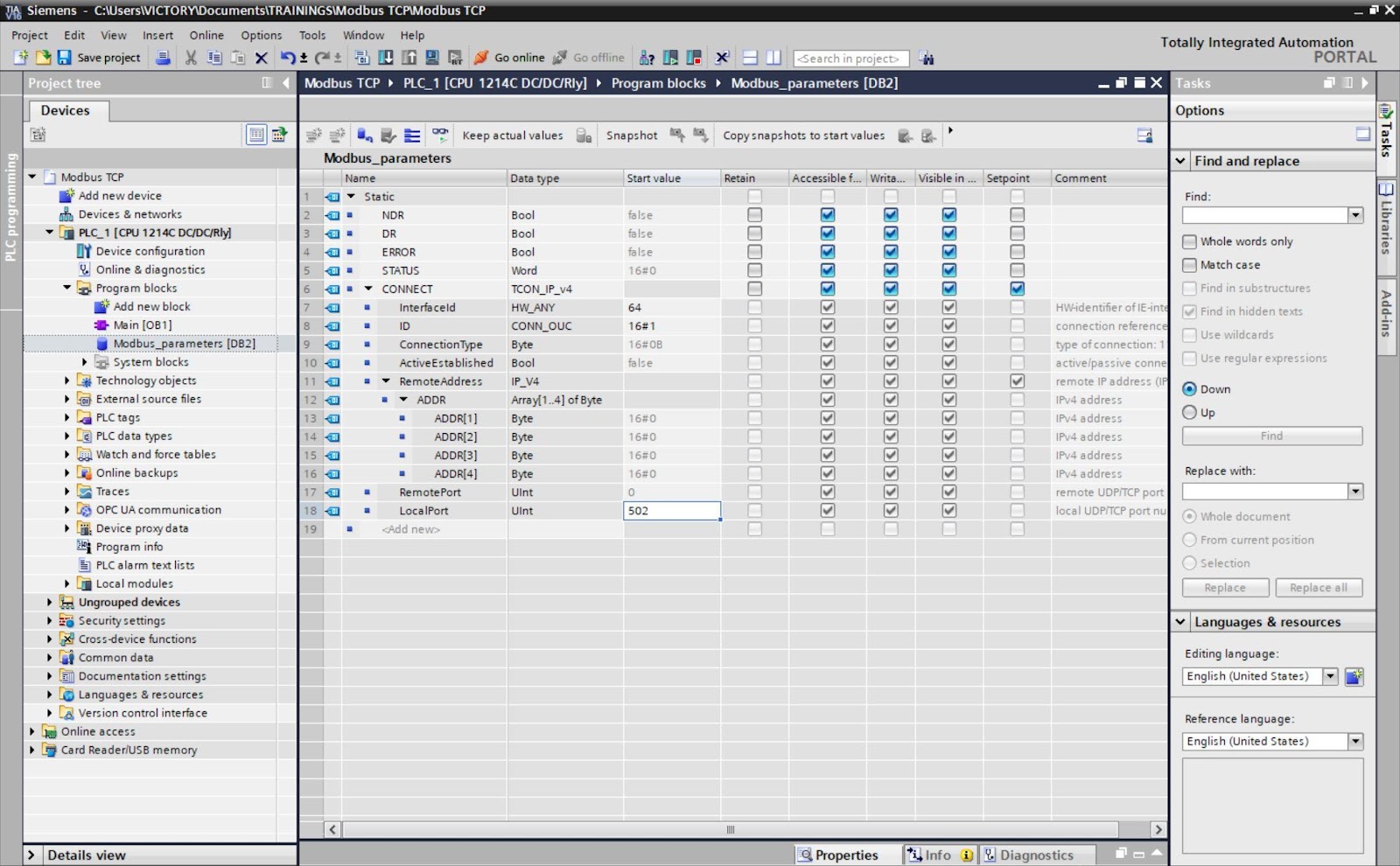
Siemens Modbus communication default port is 502, this can be changed if needed.
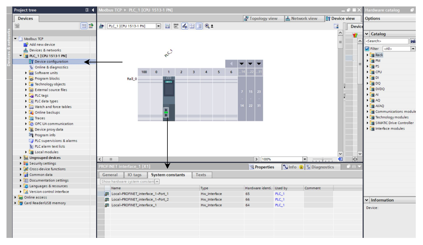
The interface ID, 64 is the HW-identifier of IE-interface submodule. This can be gotten in the hardware configuration window under system constant as shown below. Compile the data block afterward.
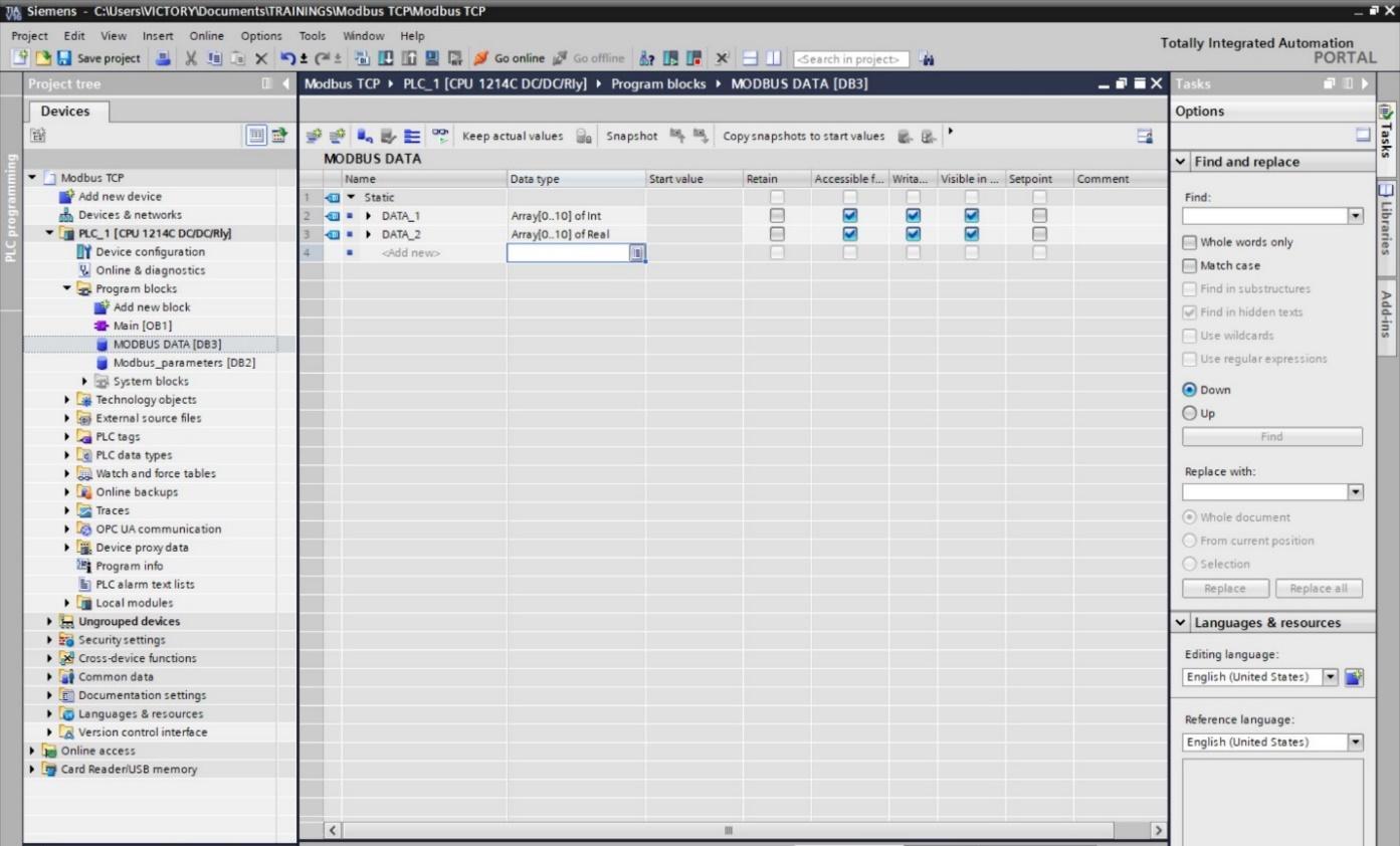
Create a new Data Block that will contain the Modbus data.
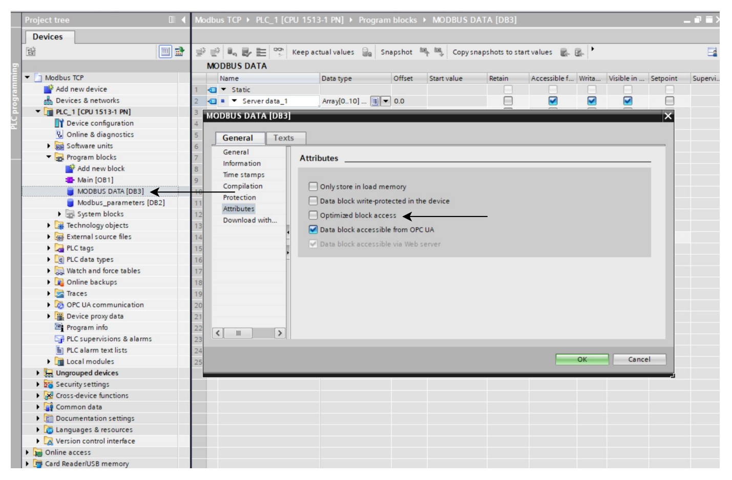
On the project tree, right-click on the Modbus Data DB and select properties then uncheck the optimize block access under the attributes pane. This will enable you to use absolute addressing for this data block.
Finally, compile the data block and you will have something like this. You will notice that the offset pane has been added to the data block.

Configure your main block like this including all the parameters.
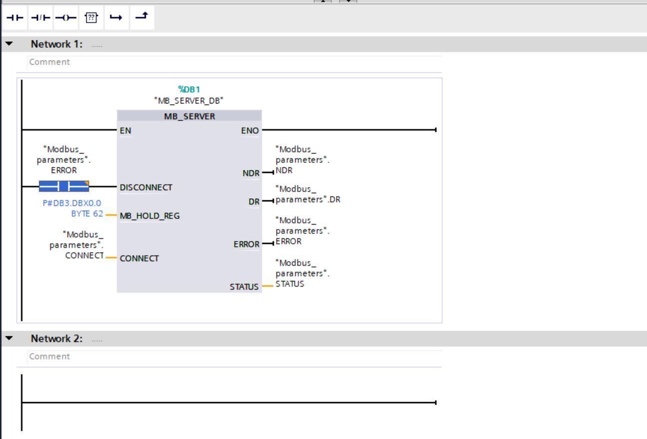
The address structure P#DB3.DBX0.0 BYTE 22 is Siemens's absolute addressing method. Here,
DB3 is the data block number of MODBUS DATA.
DBX0.0 means that the starting data offset in DB3 0.0
BYTE 62 dictates the endpoint of our data which has the offset number 62.0
Configuring PLCSIM Advanced 4.0
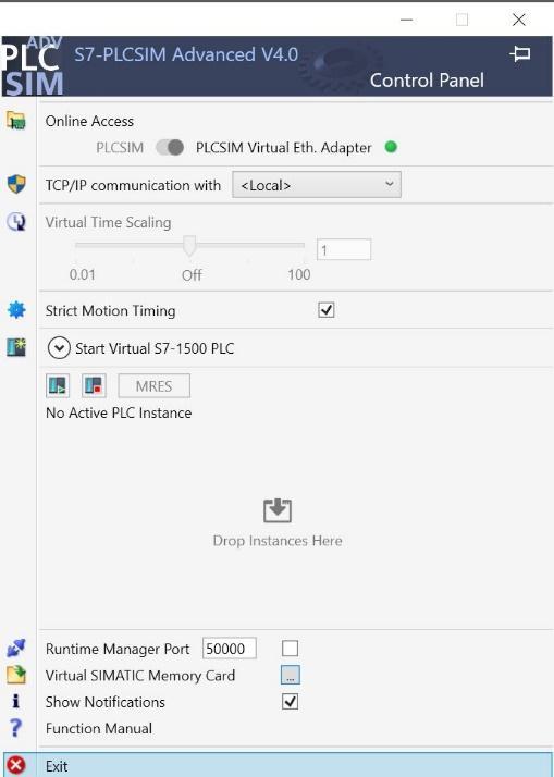
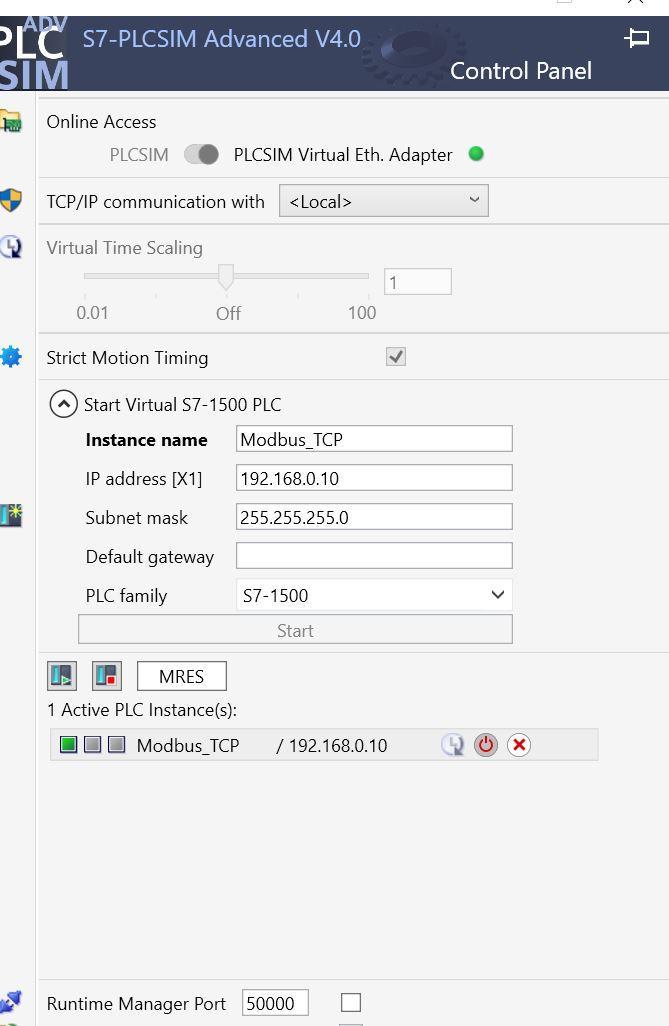
After launching PLCSIM advanced, click the button that slides to PLCSIM Virtual Eth. Adapter. This will create a virtual ethernet adapter on your workstation.
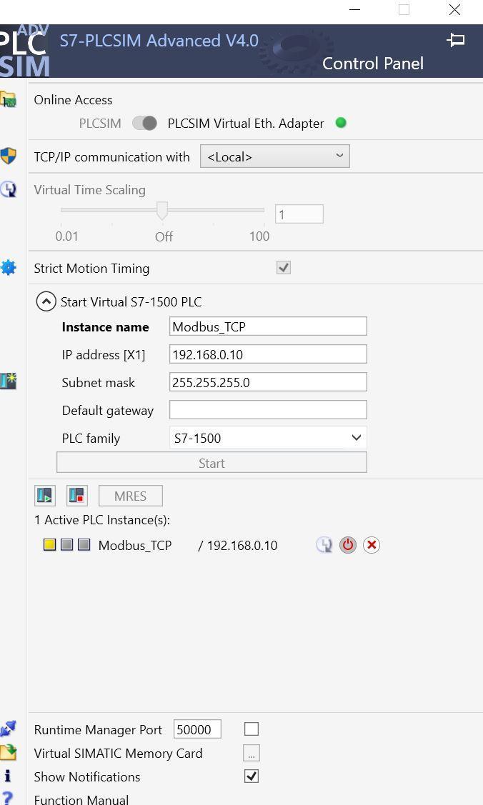
Now select Start Virtual S7-1500 PLC and configure as shown in next image. The IP address is the same as that of the PLC device we created. Note PLCSIM advanced will not work for S71200 PLC family.

Click on start to begin the simulation. Your simulation screen should look like this.
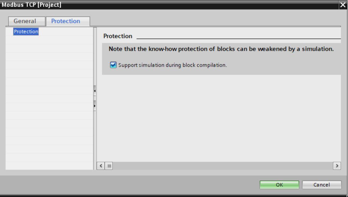
Go over to Tia Portal and download the program into the simulator. Head over to the project name under the project tree and select properties, then under protect tick the support simulation during block compilation.
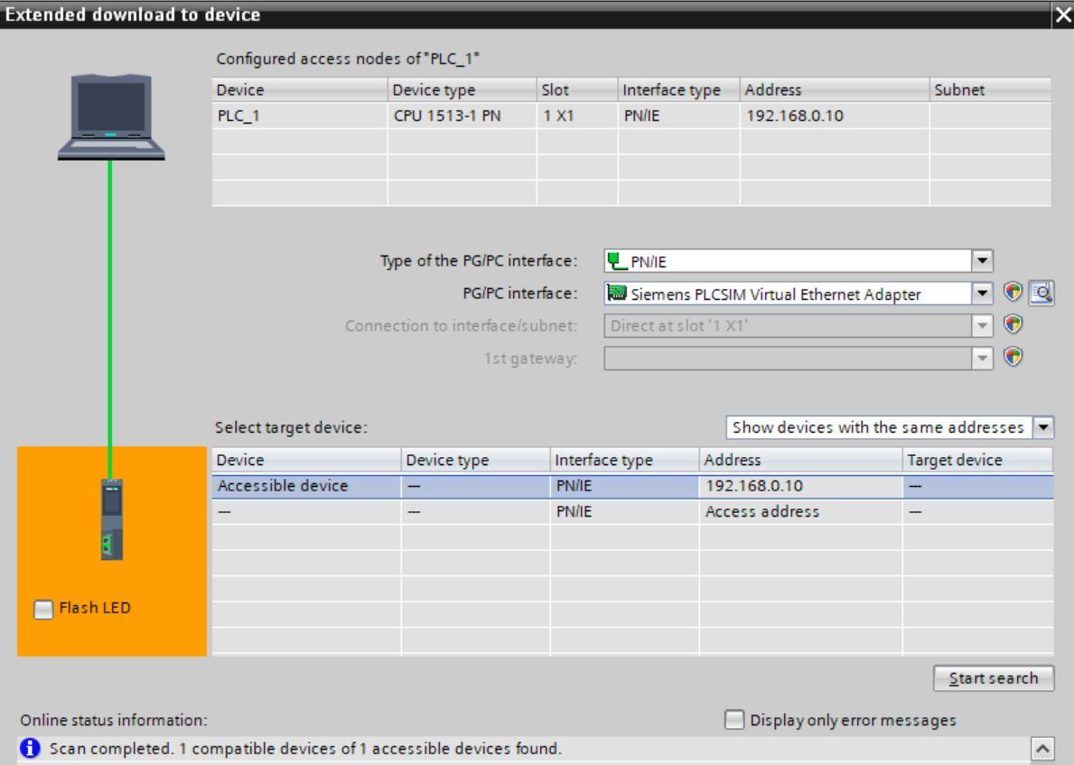
In the extend to download screen, select Siemens PLCSIM Virtual Adapter as the PG/PC interface then search.
After the PLC device is located load the program. If an assigned IP address screen pops up, select yes to continue.
Go online with the PLC and select run in the PLCSIM advanced software.
Configuring the Modbus Poll software
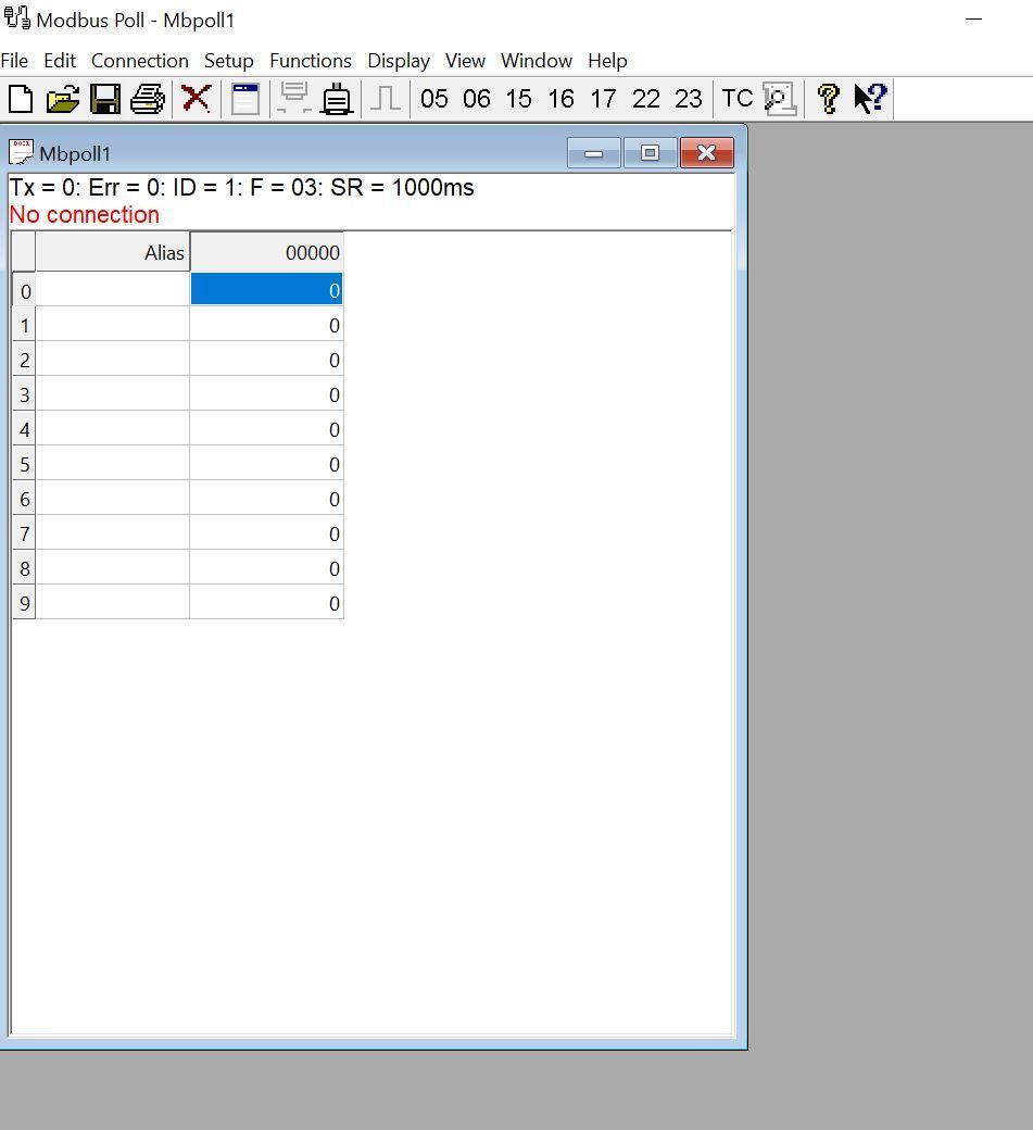
Launch the Modbus poll software and click on the connect tab.
Under connection select Modbus TCP/IP and enter the IP address of the PLC in the IP address column.
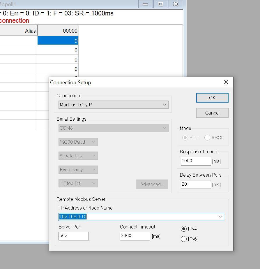
Next, select OK to start the Modbus poll connection.
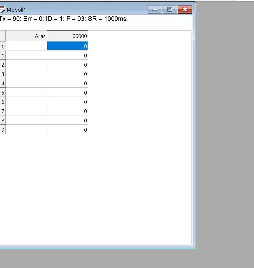
This shows we have an active Modbus TCP connection.
Reading PLC data from Modbus Poll
For Modbus devices, the number of registers in the Server/Slave must be always more than or equal to the number of registers to be read in the Client/Master else an error will be produced.
For Siemens PLCs, the Discrete Input register is the Digital Input (DI) of the PLC, the Coil register is the Digital output (DO) of the PLC. The Input register is the physical Analog input to the PLC (AI). This means that it is only the Holding register that gives us much flexibility for any type of data in Siemens.
For this tutorial, we will be reading and writing to holding registers.
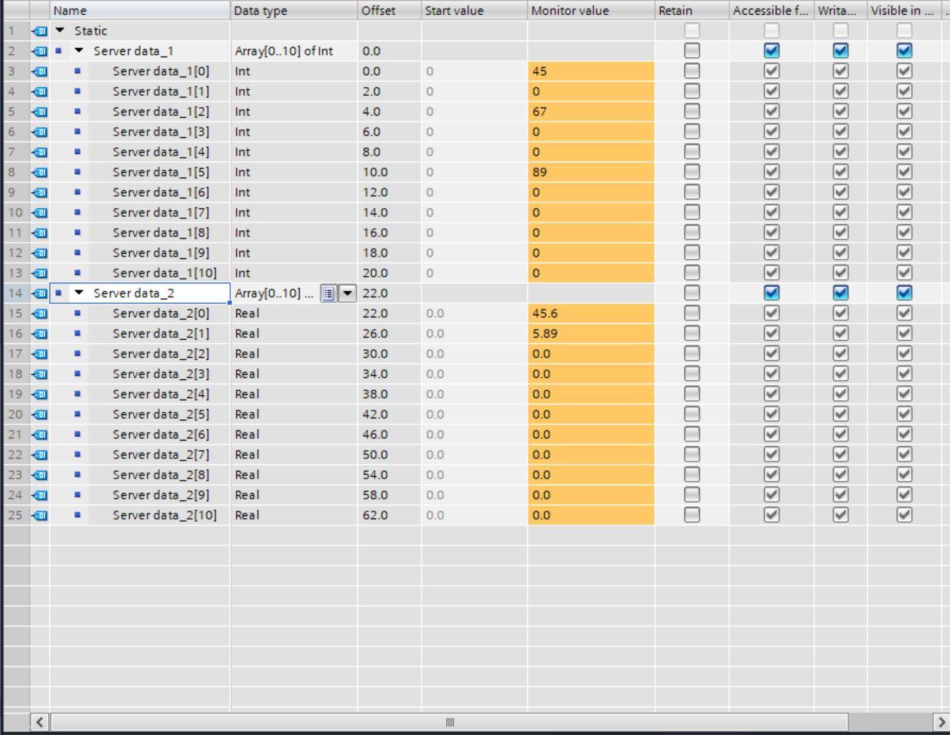
On TIA Portal, navigate to the Modbus Data register and put in some random values in both the arrays of Integers and arrays of Reals on monitor mode.
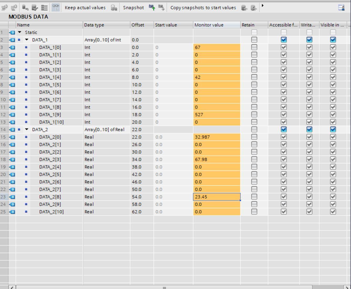
We have 11 registers of Integer and 11 registers of Real (beginning from 0 to 10). This gives a total of 33 Integer registers knowing that two integers (16 Bit) make up a Real (32 Bit).
Following the rule that the data read by the client must not be more than the server data, we will be reading 32 Holding registers data.
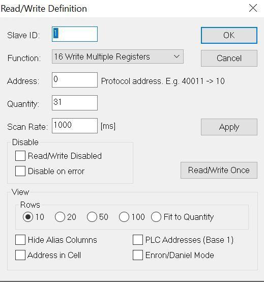
On the Modbus Poll simulator, navigate to Setup and select Read Holding Registers under function.
In the place of quantity put 31 and select ok.

As can be seen, the data in the PLC Modbus Data Block (Server) can be read from the Modbus Poll (Client).

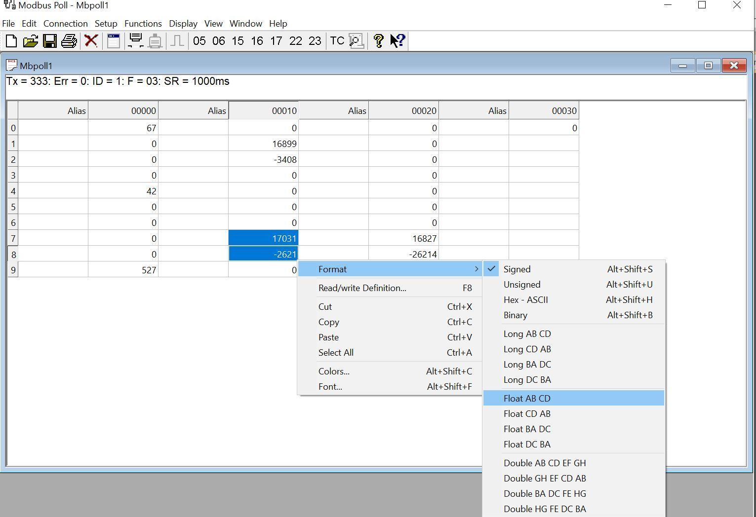
To see the floating data, highlight the two registers for the real for example the registers showing 17031 and -2621, and right-click to format and select Float AB CD. This will change the format to be seen as a Real data type instead of integers.
Doing the same for the other real registers, the final outlook becomes the following as shown in the next image.
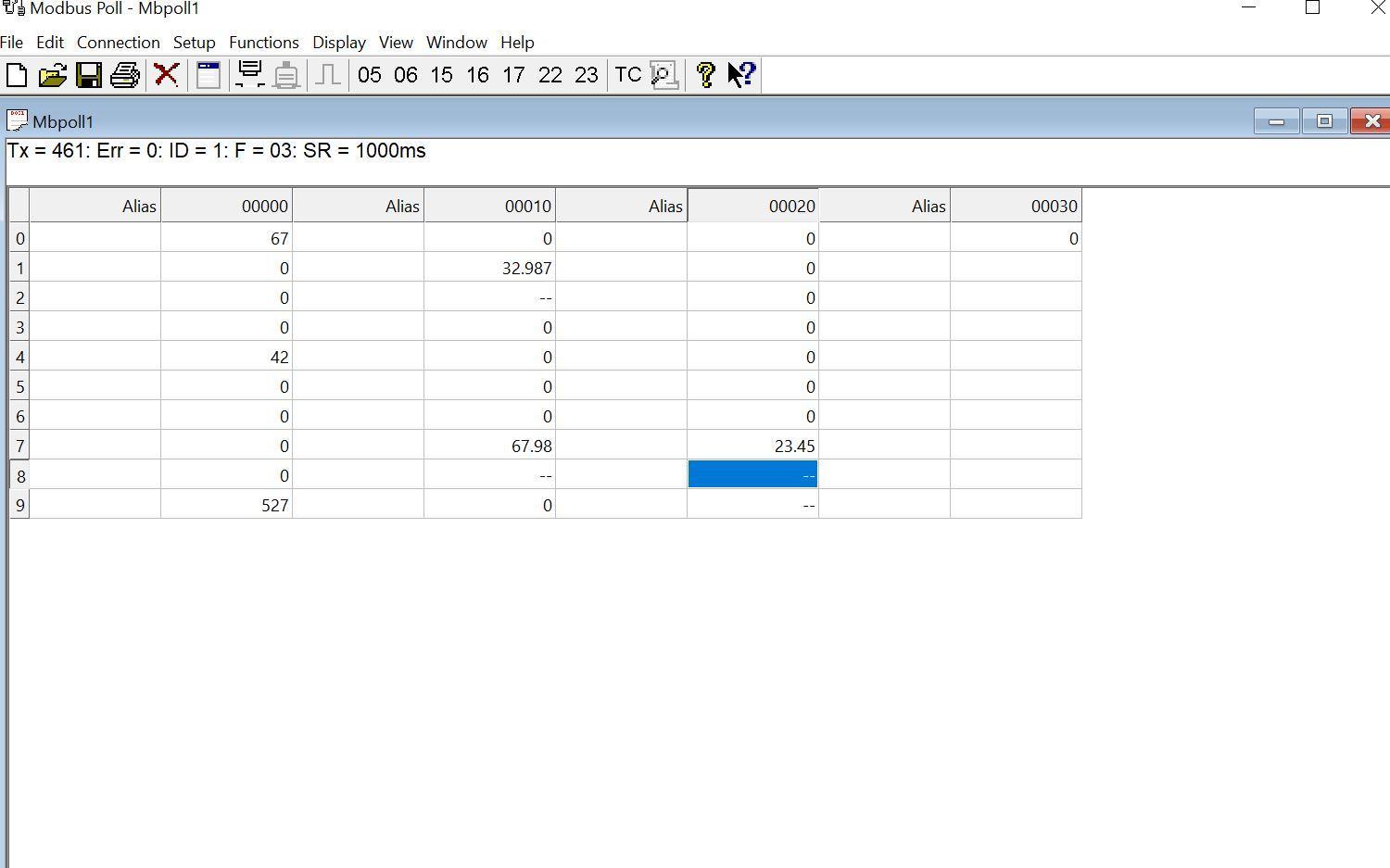
This shows we have successfully read data from the Siemens PLC (Modbus Server) to the Modbus Poll simulator (Modbus Client).
Writing data from Modbus Poll into the PLC
For the writing of data, under setup select, write multiple registers, and click ok.
We have written the following data in Modbus Poll 1268, 3586, 984.67, 45.893
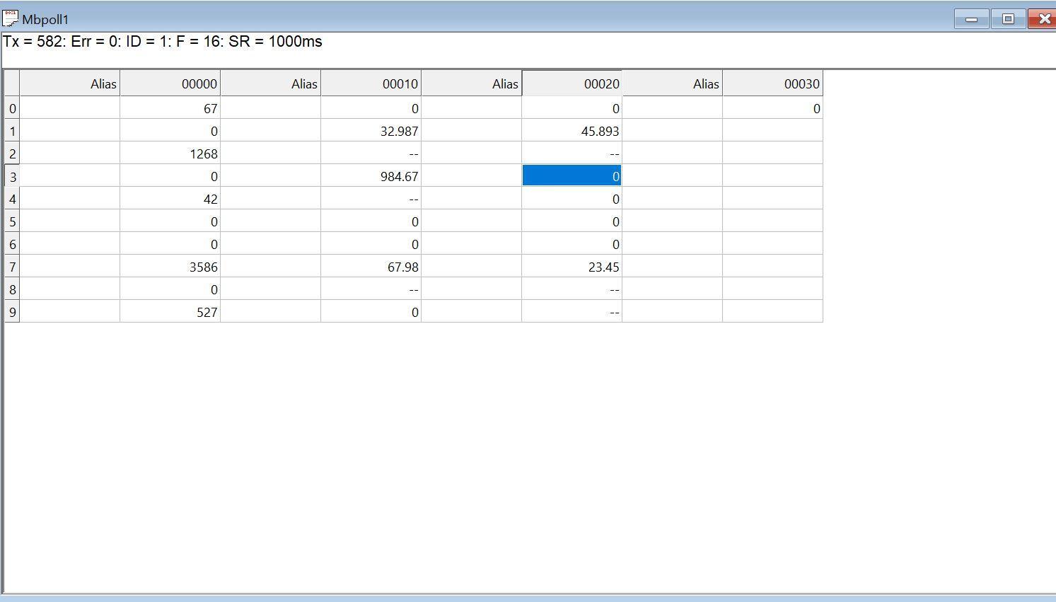
Heading over to TIA Portal, we can see the data written in Modbus Poll.

Configuring the Modbus client
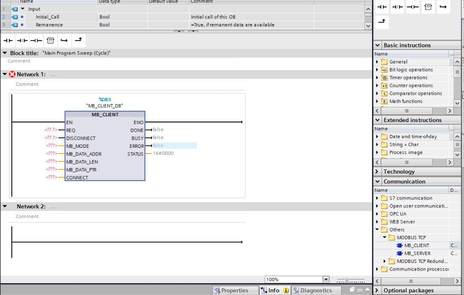
The configuration of S7 1500 as a Modbus Client device is different as a Server. Firstly, Navigate to Communication then select the Modbus TCP client block from the Others dropdown. It will prompt you to create a DB select ok.
The following is the description of the parameters
REQ – This is the request parameter to begin a Modbus session. This means that as long as the input is set (REQ=true), the instruction sends communication requests
MB_MODE – This parameter selects the mode of the Modbus request (read, write, or diagnostics) or direct selection of a Modbus function. Mode 0 is for reading Modbus registers while Mode 1 is for writing to Modbus registers.
MB_DATA_ADDR – This is the register number for the different registers in Modbus and it depends on the MB_MODE. A comprehensive list can be obtained by accessing help in TIA Portal. You can do this by simply pressing the F1 key on your workstation.
MB_DATA_LEN – This parameter dictates the number of bits or words for the data access.
MB_DATA_PTR – This is a pointer to a data buffer (Data Block) for the data to be received from the Modbus server or to be sent to the Modbus server.
DONE – The bit at output parameter DONE is set to "1" as soon as the last Modbus job is completed without errors.
BUSY - 0: No Modbus request in progress and 1: Modbus request being processed. The output parameter BUSY is not set during connection establishment and termination.
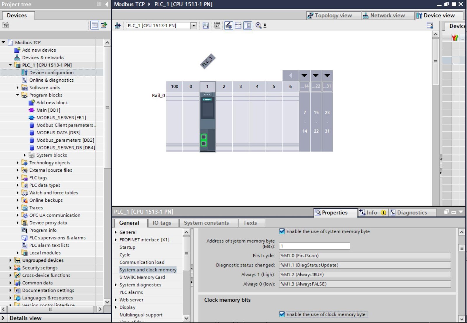
To activate clock and system memory functions, navigate to device configuration, double click on the CPU and select system and clock memory, and check Enable the use of System memory Byte and Enable the use of clock memory byte.
After doing the above, on your workstation assign an IP to the Siemens Ethernet Virtual adapter in the same IP class as your PLC. This can be accessed from Network and Internet settings on a windows machine.

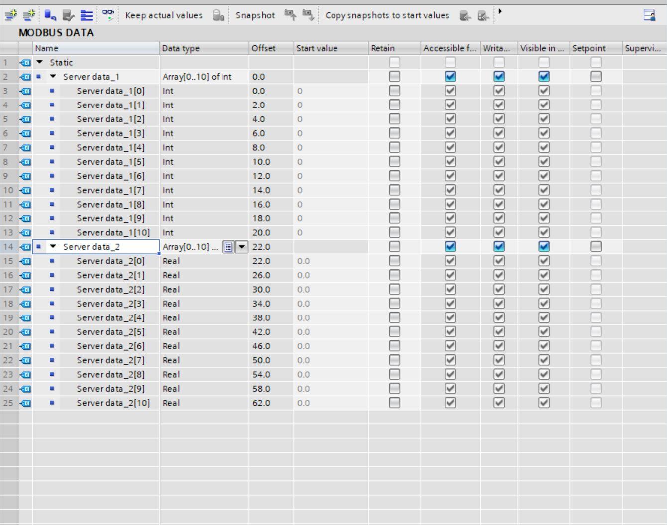
Create a new Data Block and configure the parameters as follows.
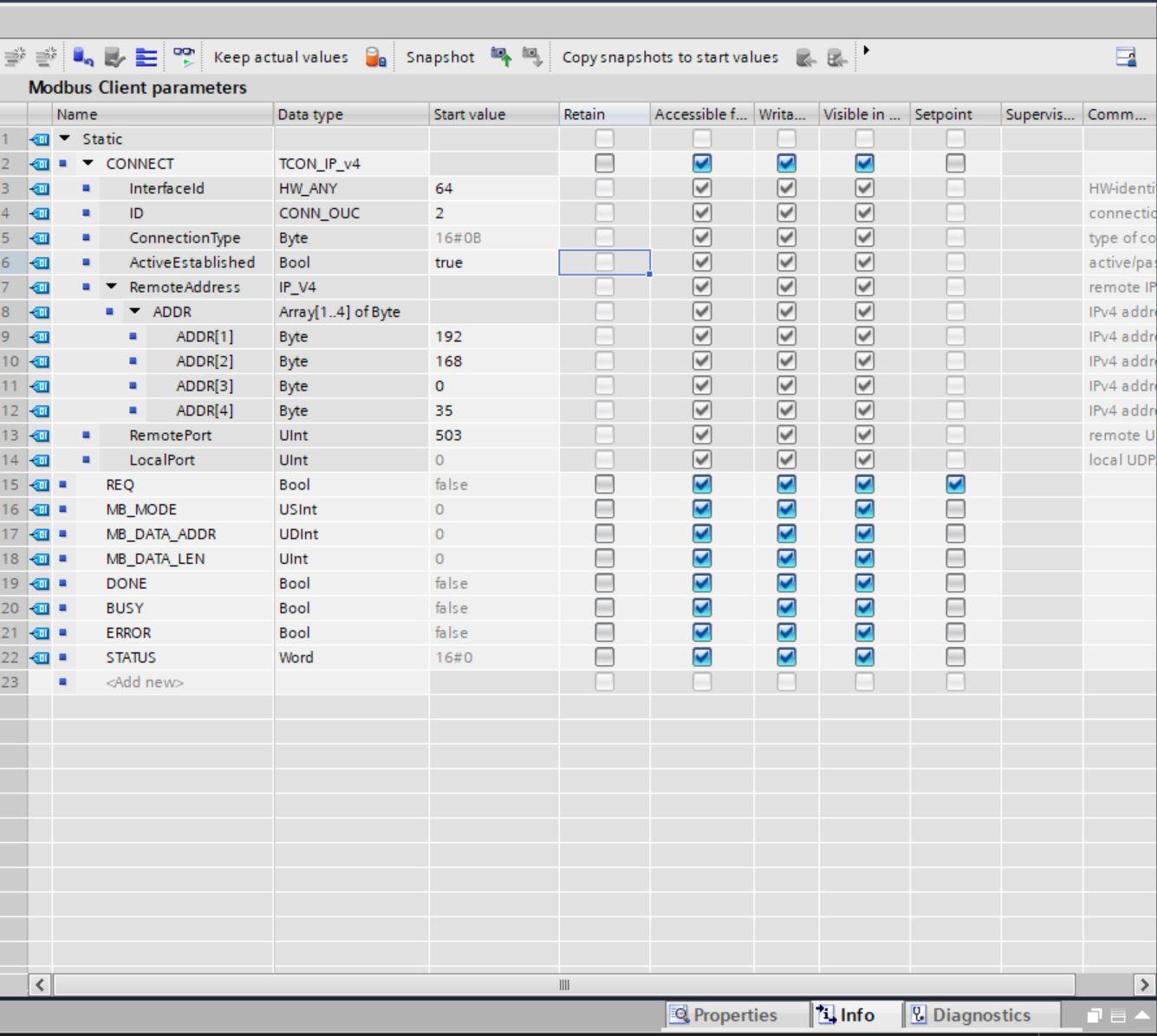
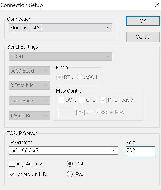
Port 503, is placed under remote port cause that is the port number we intend to use for the server. We create another DB for the holding registers with 10 Integers and 10 Reals.
Thereafter, configure your MB Client block as shown below
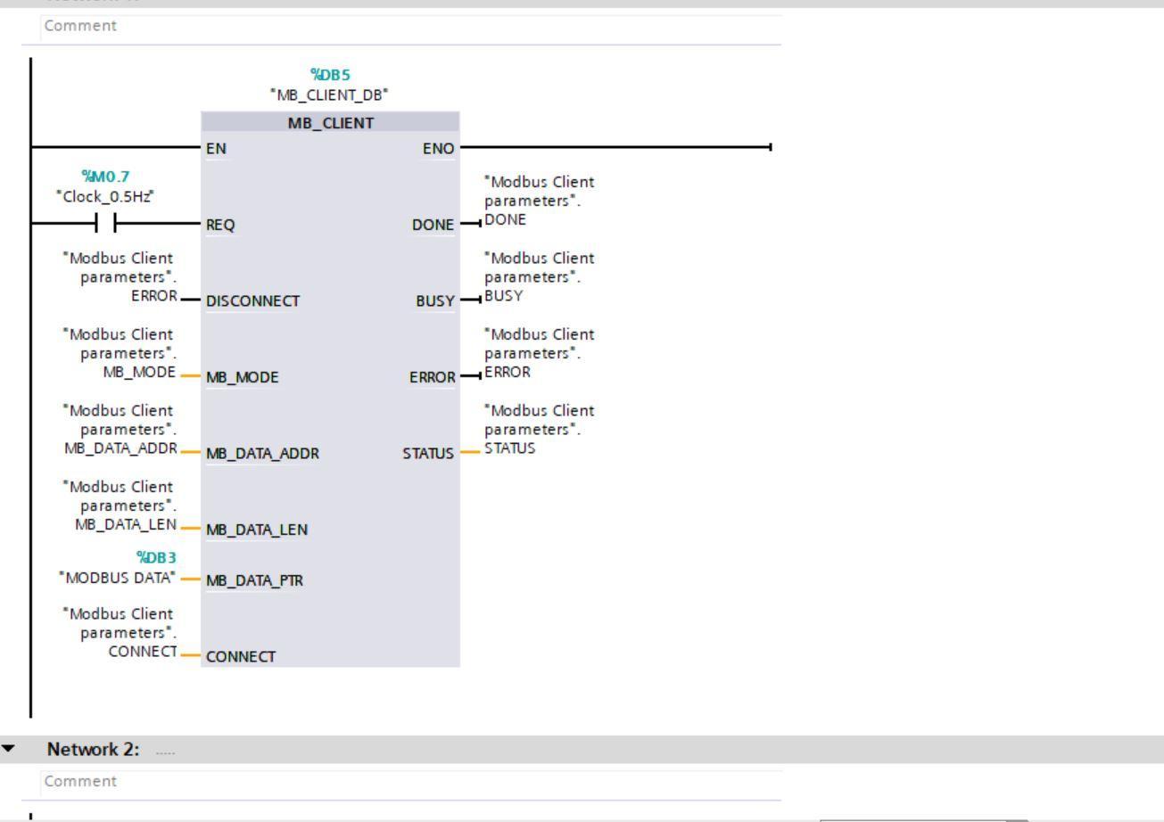
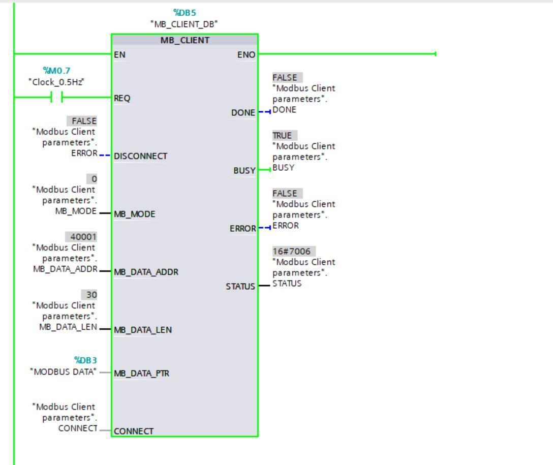
Compile the program. Download the program into the PLCSIM Advanced simulator. Start monitoring your program and modify your parameters MB_DATA _ADDR and MB_DATA Len as shown below. The DATA ADDR 40001 indicates the first holding register number as the starting point. MB_Mode 0 means the Modbus client is currently reading data from the server.
Configuring Modbus slave to read data from the PLC
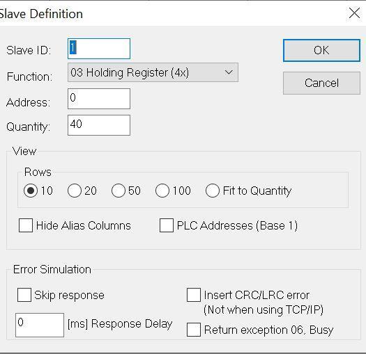
Launch the Modbus slave software and navigate to setup and then slave definition. Set the quantity to be 40. Remember the Server registers must be more than the Client.
Open the connection tab and click connect, then configure as follows and click ok when done.
The Modbus server is ready to take in data. Edit your data as can be seen in the image below

On TIA Portal, checking the MODBUS Data Block the data can be seen.
This has shown how to read data on a Modbus server into a Modbus client in TIA Portal. To write data from TIA to the Modbus server simply change the MB_MODE parameter to 1 on the MB_CLIENT block.
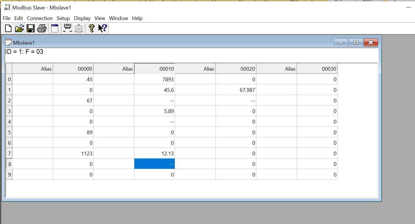
Writing data from the PLC to Modbus slave
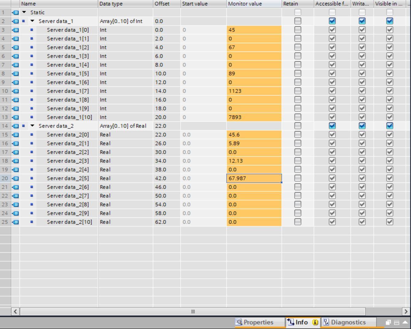
We have written the data 1123, 7893, 12.13, and 67.987 on TIA Portal Modbus Data Block.
On the Modbus Server Simulator, we can see the following data written from TIA Portal in the corresponding data locations.
Conclusion
Modbus TCP protocol is a protocol that every automation and controls engineer/technician should have under their belt.
In this tutorial you learned how to configure a Siemens S71500 PLC as both a Modbus Client and Modbus server, you also learned how to read and write data over the Modbus network, and how to use PLCSIM Advanced for advanced simulation functions in TIA Portal.
The Modbus slave/poll simulator can be replaced with a physical Modbus device since the configuration is the same. The same configuration also applies for both S71200 and ET200SP range of controllers.
The industrial automation space has various protocols - EtherNet/IP, Modbus, Profinet, TCP/IP, ProfiBus, RS-232, and much more...
