Getting Started with Siemens SIMIT Simulation

Introduction
It is important to test every piece of PLC code we write to validate it performs as expected. This can be difficult using standard simulation emulators such as PLCSIM for Siemens (and RSEmulate for Allen Bradley). PLCSIM provides us with a virtual controller in which we can test sections of code, make sure there are no obvious programming errors and simulate I/O changes. It can’t simulate real-world plant operations.
That is where the Siemens SIMIT can be of use. SIMIT is a simulation platform that is capable of comprehensive automation project testing, and process commissioning all in one platform. It can also be used as a training tool to teach operators and maintainers how to efficiently run their plant.
Before we begin, check out our previous tutorials based on PLCSIM where we can find out How to Install and Get Started with SiemensTIA Portal and S7-PLCSIM and Siemens PLC Programming | Ladder Logic, HMI Development & Code Simulation.
In this tutorial, we are going to enter into the world of SIMIT and look at how we can begin to develop a project that can be used for full plant automation!
Installing SIMIT
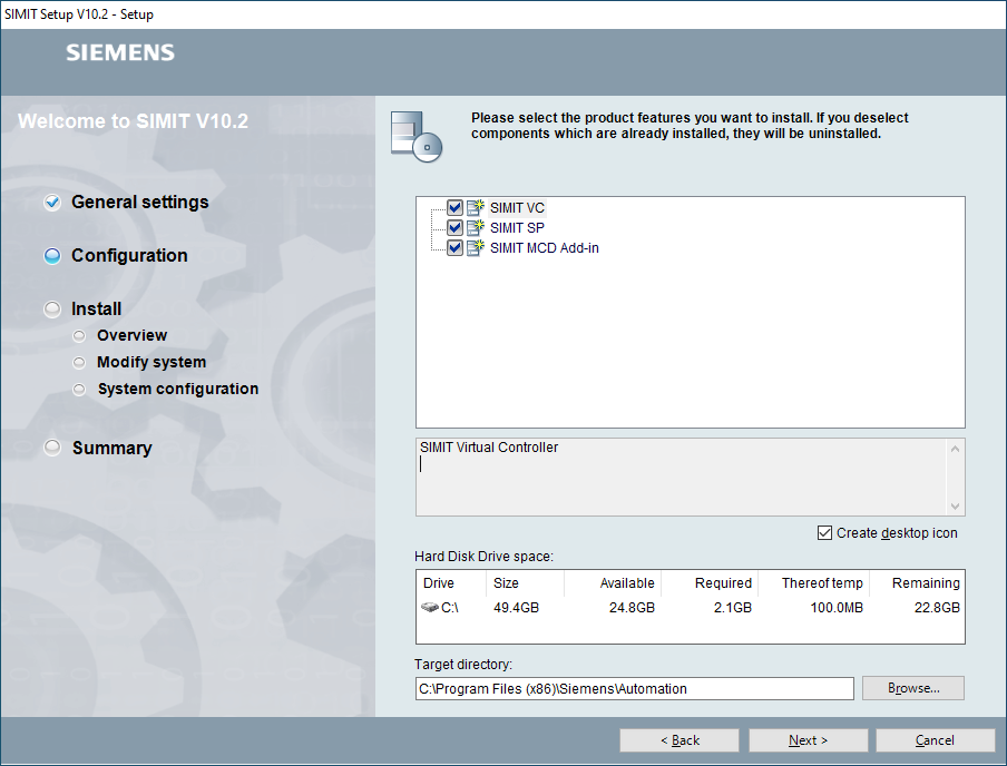
In this tutorial, we will use SIMIT V10.2. Once installed, SIMIT will be available as a demo that allows you to get familiar with the software by creating projects using built-in components. The SIMIT Demo version has a few restrictions that you should be aware of;
- Simulation runtime is limited to 45 minutes of use
- Only one Coupling type can be defined
- Snapshots are not available
- Any projects, macros and templates created in the demo version will not be able to be ported across to the full version and will remain accessible only by the demo product
The only limit applied in the full version is to the number of connections allowed. This number is based on the licence purchased;
SIMIT S - Up to 2,500 (+10%) simulation tags - e.g. for small machines
SIMIT M - Up to 15,000 (+10%) simulation tags - e.g. for a production line
SIMIT L - Up to 200,000 (+10%) simulation tags - e.g. for PCS 7 projects
SIMIT XL - Up to 1,000,000 (+10%) simulation tags - e.g. for Operator Training packages
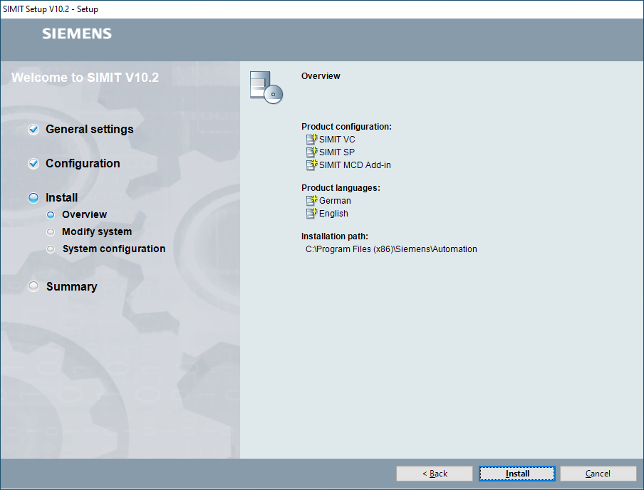
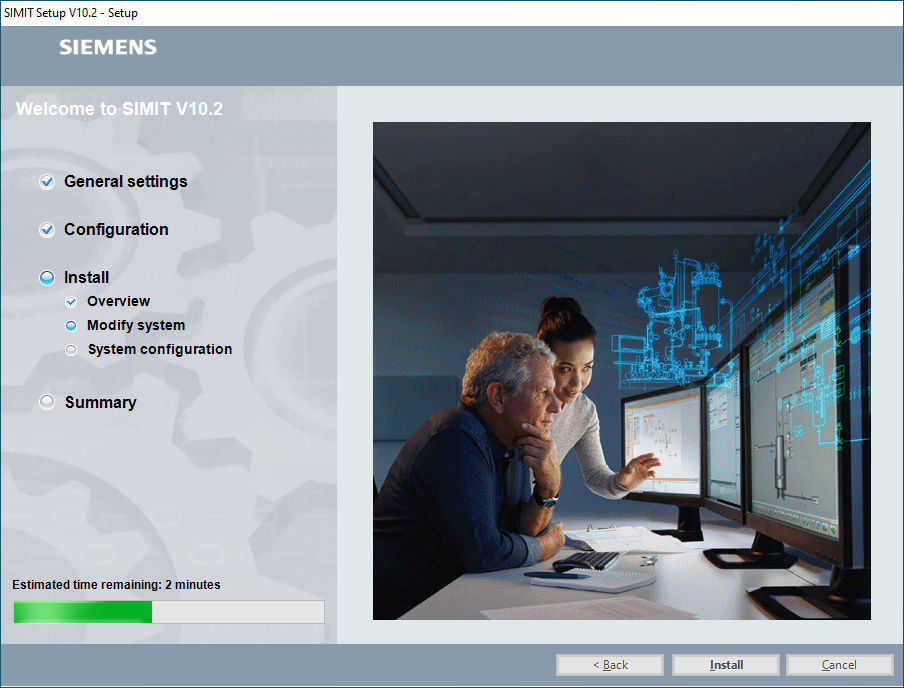
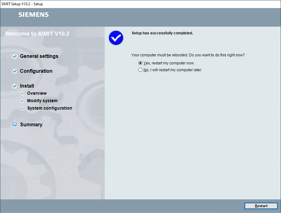
After accepting the license agreements, we get to the final installation screen before proceeding with the installation itself. Once installed, a quick restart and we are ready to go.
Starting a SIMIT Project
SIMIT has a similar style to TIA Portal, so it should be quite familiar to most people. To get started, we can either open a previous project, create a new one or retrieve an archived one. For this tutorial, we’re going to create a new project.
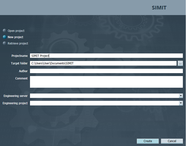
When we’ve clicked the “Create” button, we can view the project tree on the left-hand side. The first thing we should do is to set up our “Coupling”. A coupling is an interface between SIMIT and a coupling partner, for example, an automation system.
A coupling has the following tasks:
- Signal exchange with the coupling partner. The input/output signals of the coupling partner are exchanged with SIMIT over the coupling.
- Coordination of signal exchange between SIMIT and the coupling partner
There are three different types of coupling in SIMIT:
- Coupling with a real SIMATIC controller
- Coupling with an emulated SIMATIC controller
- Coupling with an external partner
So you can see that we can also use a simulated PLC, such as PLCSIM, to act as our controller, meaning we can now bridge the gap between emulation and real process automation.
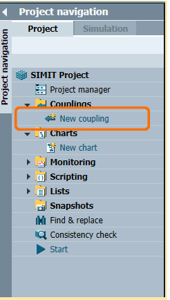
When we have selected to add a new coupling, we can choose what type we’re going to use.
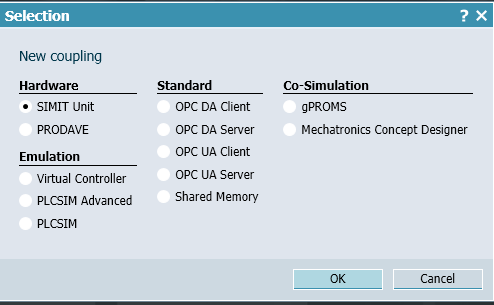
Different types of Coupling
There are several different types of Coupling available to choose from. Here is a brief overview of what some of the most common types of Coupling connections are used for.
The "SIMIT Unit" is used as a link for communication between the controller and SIMIT. The SIMIT Unit maps the behavior of devices at the bus and enables the exchange of data between the controller and SIMIT. It can simulate both PROFINET IO controllers and PROFIBUS DP masters.
The “Virtual Controller” simulates the response of a SIMATIC controller of the type S7-300 or S7-400. The Virtual Controller is loaded with the original PLC user program. The field device level and its connection over distributed bus systems are ignored. Instead, process simulation is connected directly over the process image input and output.
SIMIT uses the PLCSIM Advanced coupling to communicate with PLCSIM Advanced over a software interface of PLCSIM Advanced. SIMIT uses the PLCSIM Advanced coupling to cyclically exchange data of the I/O area of the configured S7-1500 stations. For this type of connection, PLCSIM Advanced V3.0 or higher must be installed.
SIMIT uses the PLCSIM coupling to communicate with PLCSIM over a PLCSIM software interface (Prosim). When the PLCSIM coupling is used, PLCSIM and SIMIT must be installed on the same computer.
An OPC Client connection can be used for a project that uses either PLCSIM or a real CPU. This aids in transitional testing from a virtual simulation package to hardware, controller-based commissioning.
Creating Macro Components in Siemens SIMIT
Macro components can combine repeated functions of a simulation model in a single component. This is similar to Function Blocks or Function Calls programmed in a PLC. Once a macro is created, it can be reused throughout the project by dragging it onto a chart from the task card. It can then be configured by adding tags or linking them to other macros or components.
Note that Macros can be version-controlled to assist in identifying a functional library.
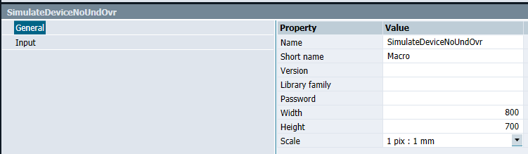
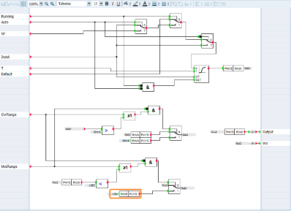
When creating a Macro, the inputs are positioned on the left-hand side, and the outputs are positioned on the right. The above example is a Macro to implement an analog scaled value. You can enter a Real value, for example, 3.00, into an input box named “Input”, and the Macro will calculate a scaled Integer value.
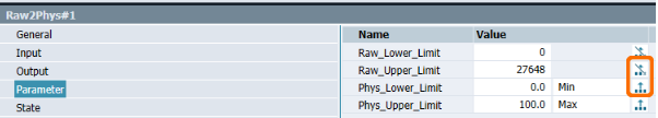
When converted from a Real value into an Integer output, it is important to consider the scaling factors of analog devices. In a project with multiple devices there will be different scaling factors. By selecting the “Raw2Phys” component, you can configure these scaling factors. Since we are using a Macro, we must enable these parameters to allow them to be assigned outside of the Macro. This can be done by clicking the button on the right-hand side of the properties window as shown in the image above. A unique name can be given to each parameter to make it easier to identify. It is not important at this stage what the value of “Min” and “Max” is because these will be defined by our device outside of the Macro. The values of the Raw Lower and Upper limit shall be defined here as they are not configured for outside use.
Creating Templates in Siemens SIMIT
Templates provide a visual display for you to interact with. Macros can connect up to Templates to allow quick and effective programming, but the Macro information is limited in its ability to give a quick visual response. The Template can show as much, or as little information that is required and can be completely configured to be used for multiple devices.
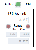
The above template contains all of the information required to be displayed and is the accompanying partner to the Macro detailed earlier. This includes an input box to enter a Real value, an input to select an automatic mode of operation, and two inputs to allow the device to be overridden to an Under Range or Over Range value.
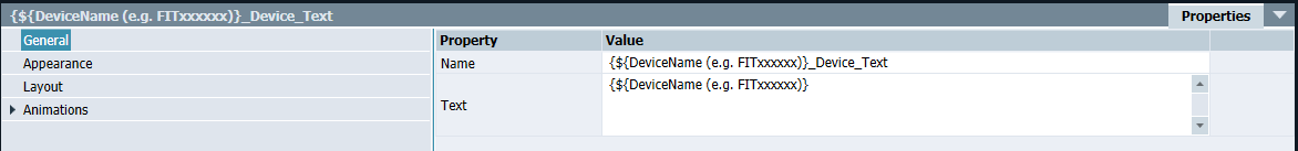
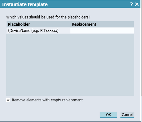
The format for entering a unique value can be seen in the image above. When this Template is instantiated, a box will instruct you to enter a device name. This is known as a Placeholder. You can enter the Placeholder name as instructed in the text. When the Template is Instantiated, each instance of the Placeholder will be replaced with the device name entered.
This Template is a simple example requiring only one Placeholder to be entered. Some Templates, depending on their complexity, will require multiple entries.

The above image shows the link from the Device Name you entered and the “Min” scaled value we looked at in the Macro earlier.
Instantiating Multiple Templates onto a Chart
In SIMIT, it is possible to instantiate multiple instances of a Template in one go. This means we can have a list of devices and simply enter device information into a file exported from SIMIT. This substantially speeds up the process of adding Templates to Charts.
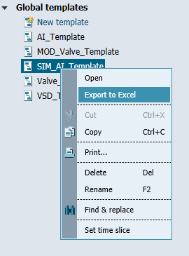
When you export the Template to Excel, it will open Excel if it is installed on your machine. Note that the file can be transferred to another computer for editing.
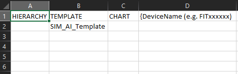
The first three columns are standard for any Template. The information after these three columns is the custom Template information and is required to complete the instantiation successfully.
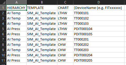
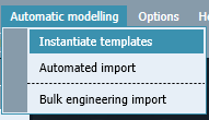
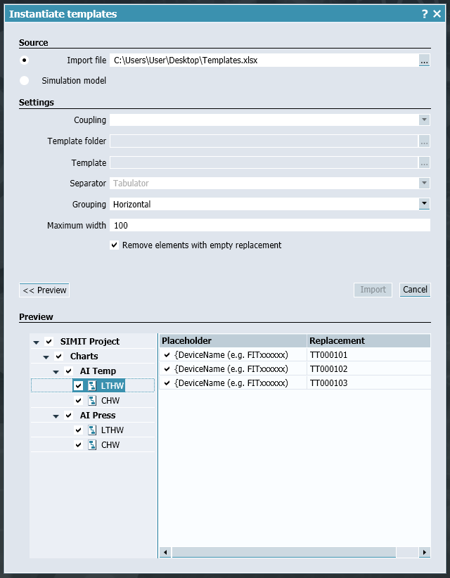
The image above has the information required populated in the fields. In the Charts window, we can expect two new folders to be created called “AI Temp” and “AI Press”. Within these folders are two Charts called “LTHW” and “CHW”. When we select the “Automatic Modelling” menu, we can choose “Instantiate Templates” to import the file we just created and instantiate our new devices.
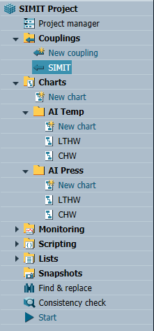
These Charts can now be added to any layout view. They will connect to the associated Macro and display the relevant data.
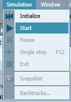
Starting the Simulation
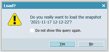
When we are ready to begin the simulation, we need to go to the “Simulation” menu and select “Start”. This will initialize the simulation parameter and start the simulation. If we select “Initialize”, then only the simulation parameters will be initialized but the simulation will not start running. When the simulation is running, it is possible to take a “snapshot” of the running parameters. This will create a file under “Snapshots” that will be available in the simulation runtime to load. The Snapshot values can be considered known-good values for a certain scenario that can be loaded to speed up a factory simulation set-up. Note that snapshots are not available in the demo version.
Conclusion
When creating a SIMIT application, a variety of different objects can be created to aid us in being able to quickly add devices to a project. The Macros and Templates created can be used for any project.
We learned that SIMIT can have multiple types of Coupling to connect to a variety of controllers or virtual controllers including PLCSim and OPC connections. Macros are the brains of the operations in SIMIT. Using component blocks we can create any number of functions to operate devices or perform calculations. Templates are like faceplates where they are our visual display of what is going on.
Finally, we learned how to take the simulation online and use snapshots to load a set of known values. This is a great tool to set a simulation up so that we don’t have to go around and manually set everything by hand.
We hope you have enjoyed this tutorial on SIMIT. It is a very powerful simulation tool that can simulate full production lines, enabling safe testing and operator training.
