PLC Alarm Programming - Fault Capturing Example in Ladder Logic RSLogix 500 Allen Bradley

Introduction
Alarms, Faults, and Warning play a critical role within every PLC Program. This logic allows the programmer to capture any abnormalities, alert the operator of a failure, and prevent system damage. Ultimately, this code is needed to make sure that equipment is brought to a safe condition after a critical failure.
These conditions can be detected by sensors, be the result of certain operator errors or be programmed in software. Whatever the source of the error, the system must be able to capture the occurrence and to act accordingly.
A common question and debate between PLC programmers is the distinction between the levels of faults & the proper designation of each one. My approach is quite simple: a fault will cause a stop of a certain process; a warning will only be a visual indication for the operator. In other words, there are two types of errors: one which will cause a stop and the other which will not. However, the programming of these is absolutely the same. The final outcome will be determined by the programmer.
Basic Alarm / Fault Best Practices
As you work & observe the Alarm structures within PLC applications, you’ll notice that they generally follow a similar structure. The reason for this, of course, is that there are certain principles when it comes to alarms, faults & warnings. Here’s a brief list of some of these best practices which I’ve discovered over the years.
- Alarms must reside in a separate routine.
- It’s easy to be confused by the general logic written by another programmer. However, alarms, faults & warnings are the most critical items as they protect the process from failure. Therefore, it’s important to make them easily accessible & visible to a novice programmer, technician, etc.
- Alarms must remain latched in until they are cleared by manual intervention.
- Remember that an alarm is an unrecoverable event. This means that the system is beyond the point of being able to stabilize itself; it will require intervention. Therefore, it’s crucial to make sure that the operator, as well as other parties at the facility, are aware of what caused the issue. Each alarm which occurred during the incident must remain active until it is addressed.
- Alarms must have a unique identifier.
- A unique ID allows one to easily refer to an alarm. Furthermore, it’s something which programmers often use to troubleshoot the system. A unique identifier displayed on an HMI screen will allow a skilled engineer to immediately trace the logic on the Programmable Logic Controller and find the root cause of the issue.
Building an Alarm Rung in Ladder Logix RSLogix500
A basic alarm rung is shown below. It’s composed of a few basic instructions which we’ve covered in other tutorials.
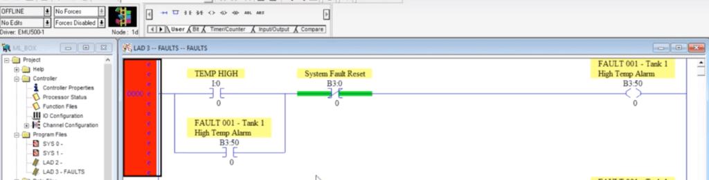
The first XIC instruction is the trigger for the alarm. This instruction may be replaced by any other which will cause the alarm to energize. Since the “System Fault Reset” bit is tied to an XIO, it will allow the final bit to energize should the “TEMP HIGH” fault trigger through the I0:0 input on the MicroLogix 1100. Once the B3:50/0 internal boolean is energized, it’s latched in place by the XIC Instruction which is tied to itself. Doing so satisfies the condition mentioned above. Lastly, the only possible means of de-energizing the fault after it has been triggered is by using the “System Fault Reset” bit. This bit is tied to field buttons as well as an HMI button in the “Main” routine.
Do note that in RSLogix500, it’s not as simple to give tags a meaningful name. Therefore, a description containing a unique ID is given to the fault bit. This is used as a reference to the fault & will be used for the HMI application.
Expanding the Structure to Infinite Alarm Conditions
Now that we have a finished rung, we can copy & paste it as many times as needed until we’ve covered all the alarms. Of course, we need to update the tags we’re using for triggering the alarm as well as the alarms themselves. The reset bit should stay as is. Here’s what a structure of the second alarm looks like.
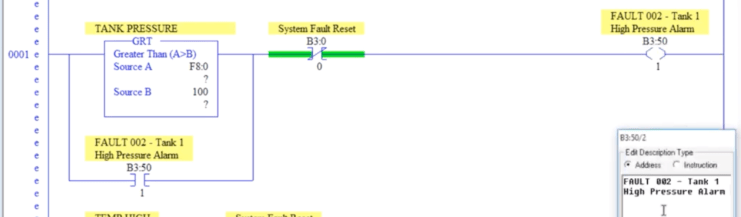
Do note that the trigger has changed to a GRT Instruction. This is because the simulated signal which will trigger this alarm is an analog value. Therefore, it’s not an internal bit, but rather a limit which was set by the programmer.
Utilizing Alarms for a Single Process Stop
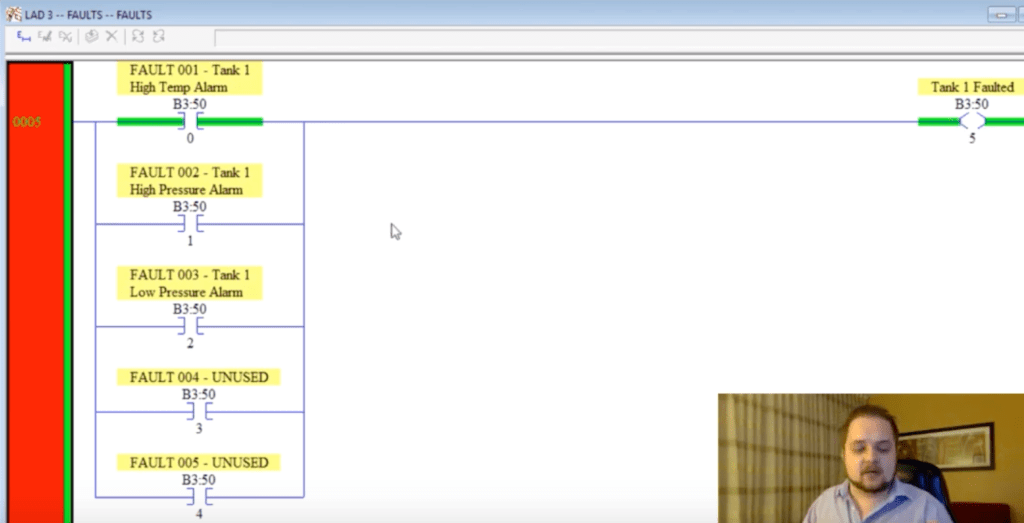
Now that we’ve defined multiple rungs which represent unique alarms/faults, we need to make sure that we’re able to stop the process in case of a failure. This can be done by inserting a condition for each alarm into the “Main” routine. However, a much more elegant way would be to utilize area identifiers of failure. These bits will aggregate multiple alarms and can be utilized to stop a single area. This makes the logic much easier to read and allows the programmer to segment the different areas from within the alarm routine.
Here’s an example of the main area (Tank 1) fault status which aggregates 5 different alarms that we’ve defined previously.
Conclusion
Alarms, Faults & Warnings are crucial components of every automated system. They are used to prevent damage, critical failure or injury to an operator. These alarms much are defined in a clear and structured manner in order to be effective, be easy to troubleshoot & provide information to anyone working with them.
The three main principles of each alarm are as follows: keep the alarms latched until the problem has been identified and manually reset, give each alarm a unique ID and make sure to have your alarms within a dedicated routine. Following these principles will make sure that the code you leave behind can be easily understood.
Lastly, make sure to work with a professional if you aren’t comfortable with implementing alarms. A proper risk assessment must be conducted on a process before identifying all the potential failures.
