PLC Function Block Programming for Analog Input Scaling | FBD Tutorial in RSLogix 5000

Introduction
Function Blocks are an essential programming tool in PLC programming. This method of programming allows the user to visually tie blocks of code together and utilize functions which aren’t available otherwise. Furthermore, certain PLC based logic components are much easier to implement and visualize in function blocks instead of ladder logic or structured text.
One of such implementations is the scaling function. The SCL Instruction can be found in the ladder diagram in RSLogix 500. However, it’s not available in ladder logic in RSLogix & Studio 5000. The user is required to use function blocks in order to implement the exact same calculation. Through the use of a Function Block based routine, the implementation can be completed & utilized for the purpose of analog input and output scaling.
In this article, we will be going over Function Blocks as well as the concept of input and output scaling. Lastly, we will look at a specific example of how to scale an analog input which is registered into our MicroLogix PLC.
Adding Function Block Diagrams to RSLogix / Studio 5000
In order to get started working with function block diagrams, the user must have a professional copy of RSLogix or Studio 5000. We’ve seen users confused by the fact that they simply can’t access this feature and more often than not, this is due to their license.
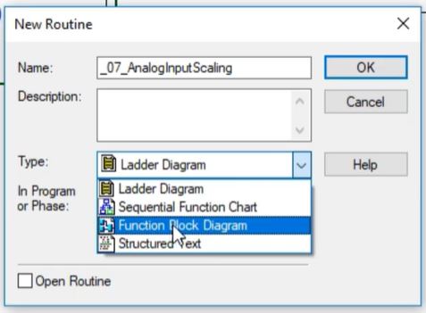
To add a function block diagram to your current program, right-click the Task you’d like it to execute under and select “Add New Program”. Once that’s done, all you need to do is change the type of the program to “Function Block Diagram” as shown in the screenshot below.
Before the logic within this routine may execute, we do need to add a JSR Instruction within the “Main Routine” of this task. This is done exactly the same way as we’ve done it for ladder logic based routines.
Utilizing Function Block Diagrams in RSLogix 5000
The first time you start using function block diagrams, they feel very unnatural. The programming methodology relies on dragging blocks onto the screen, configuring them and drawing wires between them. Although it’s very different from ladder logic, most of the programming concepts remain the same. Instead of a MOV instruction, you may simply tie an input to an output. Instead of an XIC, you may perform a boolean check. The same reasoning goes for most instructions which have a function block diagram equivalent from ladder logic.
A key difference is a fact that you need a control structure for every single block. In other words, an ADD instruction will be used by itself in ladder logic. However, the function block diagram equivalent will require you to create a tag which will contain all the parameters of this implementation. This confuses many users at first, but quickly becomes a habit in FBD.
The function block diagram interface may also confuse the user. However, it follows the same principles as the ladder logic counterpart. That being said, once you go into the “logic edit” functionality, you will be modifying the entire sheet instead of a single rung as you did in ladder logic. The sheet can be composed of single or multiple structures. You aren’t limited by anything besides the space for your instructions. It’s advised not to overfill the area.
Implementing Analog Input Scaling in RSLogix 5000
Why do we need to scale analog inputs and outputs?
The reason behind this practice is quite simple: we’re translating a value understood by machines (PLCs) into a value which is understood by humans.
A simple example would be a pressure sensor. From the datasheet, you will find that the sensor will send 4mA at 0 Psi and 20mA at 10 Psi. The PLC has absolutely no knowledge about the Psi values which are specified by the sensor. As far as it’s concerned, it’s simply reading a tag which comes into the analog input & creates an integer which is shown as 0 for 4mA and 16384 (2 to the power 14). Since you’ll be programming logic based on the Psi values of the system, it’s much more convenient to work with those values instead of the integers sent by the PLC. Therefore, we need to scale!
Scaling is very straightforward. For the example above, the SCL instruction will need to take 0 to 16384 as the input values and 0 to 10 as the output values. The linear mathematical formula will automatically calculate the Psi level from the sensor & translate it into the output tag. In other words, if the sensor input is 8192, the output will be 5Psi, if it’s 4096, the output will be 2.5 Psi and so forth.
Is it possible to avoid scaling altogether?
Absolutely!
However, imagine that you’re reading an analog signal on your input pin for a certain temperature. Within your code, you’ll need to create logic which will compare the temperature to certain setpoints and take action. For example, heat a certain ingredient to 120 degC and another to 157 degC. As you’re probably already aware, the simplest path would be to use a comparison instruction such as the LES, GRT or LIM to make this happen. This is simple if you’re working with temperatures & can easily create logic such that IF Sensor Temperature GRT Temperature Setpoint THEN Stop Heating. However, if you’re using raw values, you’ll need to calculate the value of the raw number to be equal to 120 or 157 degC.
Output scaling will perform the opposite action on your numbers. We’re looking to convert a value which we’ve been using in our code into a machine-understandable double-integer. The PLC has no idea what’s attached to the output, all it’s concerned about is that writing 0 into the register will set the output to 4mA and 16384 will set the same output to 20mA.
Scaling Through the SCP Function Block Instruction
As discussed above, the SCP instruction is an ideal way of scaling an analog input or output signal. It’s very easy to use and requires exactly the same parameters as in RSLogix 500. Furthermore, if properly implemented, the function block alternative is very visual and easy to understand to anyone troubleshooting the system. Here’s an example of such an implementation.
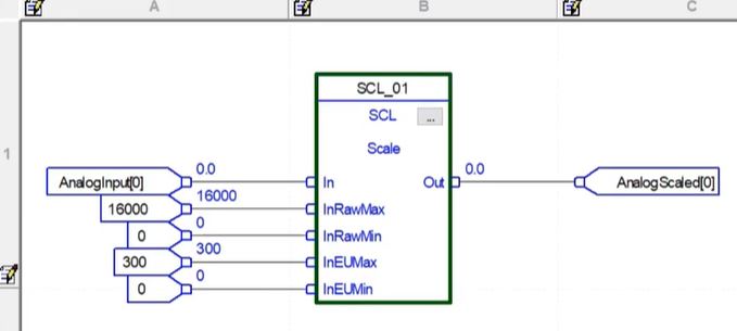
The instruction above is taking several parameters: AnalogInput[0], 16000, 0, 300 and 0. It’s set to output to a tag labeled as AnalogScaled[0]. As you drag out an SCL block, you’ll probably notice that the InRawMax, InRawMin, InEUMax and InEUMin tags aren’t visible. This is due to the fact that they’re set to be hidden by default. You may choose to leave them as such or display them on the diagram by selecting the settings menu & checking the “Vis” box next to them. We believe that having all the parameters which may be changed or need to be re-confirmed at runtime should be visible.
Once the instruction is in place and you’ve confirmed that the values correspond to what you’re looking for, you may commit the function block diagram. This will immediately begin scaling the input & writing it into the output.
Conclusion
Analog input and output scaling are performed slightly differently in RSLogix & Studio 5000 than it was in RSLogix 500. However, it’s just as easy. The best method by far is to use the same instruction we had access to in ladder logic in RSLogix 500: SCP. That being said, you’ll need to get a basic understanding of function block diagrams as this instruction isn’t available in ladder logic.
It’s also important to understand why we’re scaling in the first place. For am input signal, this is done to convert a machine value into a human understandable one. For an output signal, the exact opposite is achieved.
Don’t be afraid to dive into function block diagrams as they are an important tool of every PLC programmer. We will be building upon this concept later on as we talk about the PIDE instruction.
