PLC Programming | CompactLogix 1769-IF8 Analog Input Module RSLogix 5000 Configuration tutorial

Introduction
Although Analog devices are slowly being phased away by those with embedded & EtherNet capabilities, a lot of them are still present in the field and are being developed by Original Equipment Manufacturers (OEMs). Knowing how to integrate these devices into a plant control system is an important aspect of working with PLC Programming & automating certain equipment. Analog devices can be used to measure distance, flow, pressure, speed, rotation, weight and more.
The CompactLogix platform provides an excellent way of integrating such devices into a controller from the 1769 family. The module can receive & process up to 8 analog signals which can be of voltage or current type. Furthermore, the module is fully configurable and allows for internal scaling without the use of any other instructions within the program. That being said, I don’t always recommend this method as this makes it more challenging to maintain, move inputs around, etc.
In this tutorial, you will learn how to assemble the hardware and how to add the 1769-IF8 module into a program which is downloaded to a CompactLogix 1769-L24ER-QB1B processor.
Working with & Assembling the 1769-IF8 Hardware
The 1769 family hardware features a flexible backplane which allows external modules to be easily attached to the main controller. In this tutorial, our focus will be on the 1769-L24ER-QB1B Programmable Logic Controller and the 1769-IF8 module. Although the process is nearly the same for all other PLCs, make sure to read proper documentation as you may need an additional power supply, other modules, etc.
The 1769-L24ER-QB1B processor will only work with an end cap resistor which is purchased separately. This part is 1769-ECR for End Cap Resistor. Chances are, you have one on your PLC. Here’s an image of this part:
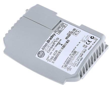
You will find a tab on this part which can be easily pulled away from the main unit by a little plastic piece which has a lock on it. Make sure that the hardware is powered down as you perform this procedure. Removing the 1769-ECR will expose the backplane which we will be using for the 1769-IF8 module.
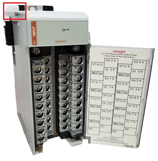
The 1769-IF module will be placed between the PLC and the ECR module. Slide it into the same position you removed the End Cap Resistor from and close the tab which makes the connection. Note that due to the size of this module, the tab is found on the top this time.
The last step in the process will be to re-install the End Cap Resistor onto the opposite side of the 1769-IF8 Analog Input module. Once again, the resistor is there to terminate the back-plane and allow the PLC to recognize the modules connected to it. In other words, it’s necessary to have it in place.
Adding External Input Modules into RSLogix / Studio 5000 Software
RSLogix & Studio 5000 make it extremely simple to add external modules into the I/O configuration of the PLC.
By opening a new program in which our PLC (1769-L24ER-QB1B) is defined, we’re able to see the default definition which features an embedded portion of I/O. We need to add the External Module which we’ve just installed right below this definition. Here’s a screenshot of where it needs to go.
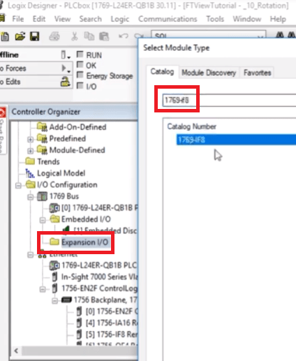
By searching for the module name within the catalog, we’re able to select “1769-IF8” & define the new module.
Configuring Various Analog Inputs on the 1769-IF8 & Scaling
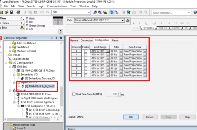
Now that we have the module in our I/O tree, we can view the configuration of each channel. From this panel, we can enable/disable a channel, set it to a different input type and configure the scaling options.
In terms of “input types”, analog signals come in many flavors. Generally speaking, you’d typically be dealing with either a voltage or current input depending on the device on the other end. We won’t go into great detail here, but in general, it’s better to use the 4-20mA signal range. It’s reliable, easy to work with and is supported across most vendors.
As far as “scaling” goes, you may choose between several types. Based on my experience, it’s easier to work with a raw signal and scale it through an SCP instruction, but the module allows you to do exactly that through the configuration panel. In simple terms, the goal here is to translate a 4-20mA signal (or whatever you chose) into a meaningful value. A good example would a level sensor. The sensor is set to read 5 feet and send a 20mA signal & read 1 foot and send a 4mA signal. The scaling will translate the 4-20mA signal back into feet or a percentage based value. These can be manipulated and used much easier as they make sense to those using the system.
Conclusion
Knowing how to work with analog input and output signals is extremely important. These signals are still used for a variety of applications all over the manufacturing floor. They can be found in range sensors, temperature probes, level sensors, valves & much more. Knowing how to work with these will put you ahead of some of the other PLC Programmers out there.
The CompactLogix platform offers an excellent way to capture an analog input into the 1769-IF8 module. This module allows the programmer to configure up to 8 distinct signals which will be tied into the processors. Once the module is defined within the I/O tree of the PLC, we can easily configure each input by setting its parameters, enabling it and giving it a scaling factor.
