PLC Programming Fundamentals – OTL Instruction

Introduction of Output Latch
The OTL, also known as the Output Latch, instruction will force a single bit of logic into a high state if all the conditions leading to it are true. It’s a basic instruction which is powerful but can cause programmers a lot of grief if used improperly or too frequently. This instruction is found on the right side of a ladder logic rung and will switch a bit to a HIGH state once it executes. Unlike the OTE Instruction, the OTL will never turn the bit LOW. In order to make that happen, you can leverage other instructions which accomplish exactly that. That being said, the most common pairing with an OTL is an OTU (Output Unlatch).
What is the purpose of the Output Latch?
In PLC programming, an output is tied to an electrical device that most often performs a mechanical action. A few examples of such devices include motor starters, relays, valves, solenoids and lights. The purpose of energizing an output is to toggle between the two states of the device tied to this output. In other words, energizing a motor coil may start the motor. Similarly, energizing a valve will toggle the state and open or close the valve depending on the initial state.
The latch portion comes into play when the output must be energized for an extended duration. In other words, once the conditions are met for the output to be energized, an output latch instruction will set the output to HIGH until it is unlatched. The rung in which this instruction is used will not be monitored until a separate condition unlatches the output through the use of an OTU instruction.
Example & Usage of OTL
Here’s a real-world scenario of an OTL instruction:
- A Micrologix 1100 Allen Bradley PLC is used to control a process.
- A motor contactor is connected to Output 0 (O:o/o of the PLC).
- A normally open push button (“System Start”) is connected to Input 0 (I:0/0 of the PLC).
- An operator presses the start button.
- The XIC instruction is tied to I:0/0.
- The OTL instruction is tied to O:0/o.
- The OTL instruction energizes the output (O:0/0) while the XIC is TRUE.
- The output (O:0/0) remains HIGH when the XIC is released.
Programming example in RSLogix 500:
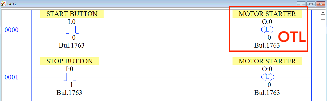
Outcome:
The OTL instruction will energize the output of the PLC which will allow the motor tied to the starter to run. The bit which was energized by the OTL instruction will remain energized after the release of the start button or any other condition tied to the input of the OTL.
Data Types Allowed for OTL
The OTL instruction will work with the following data types within the RSLogix 500 environment:
- Boolean – The OTL may only set TRUE or 1 or HIGH.
Important Notes
- Note 1 – The OTL instruction was initially used to set the status of miscellaneous outputs landed on the PLC. However, it may be used on any boolean within the program. In other words, it can energize any boolean within the program. Through this property, programmers can utilize the OTL instruction for a wide range of applications.
- Note 2 – Although it may seem like a good idea to introduce OTL and OTU instructions for every bit, there’s a catch. Depending on how the code is executed, you may run into scenarios where the logic will depend on the position of your rungs within the program. Avoid using OTL & OTU instructions unless absolutely necessary for the application.
