PLC Programming Intermediate Instructions – CTD | Count Down

Introduction
The CTD, also known as the Count Down, instruction is used to decrement the value of the counter associated with it. This instruction will detect a FALSE to TRUE transition of the logic leading to it and decrease the “Accum” value of the counter by 1. The effect of using this instruction is the exact opposite of what the CTU Instruction does to the counter. Just like its counterpart, this instruction will be found in a rung which will count a certain number of events. Due to the fact that it decrements the value, the use cases need to be very specific in order to be clear to the next programmer.
You can use the CTD instruction for every single application of the CTU instruction. In other words, it is just a matter of preference. That being said, an experienced programmer will allow the program to flow naturally; using the instruction as it would make sense in the real world. The most basic example which comes to mind would be a start countdown where the values need to decrement from 10 down to 0.
Example & Usage of CTD
Here’s a real-world scenario of a CTD instruction:
- A Micrologix 1100 Allen Bradley PLC is used to control a process.
- A “High Level Alarm” is indicated by an internal bit B3:0/15.
- A CTD instruction is tied to Counter C5:2.
- The Counter C5:2 has a “Preset” of -5. The number 5 represents the maximum number of times the alarm can be triggered before requiring an acknowledgment from the operator.
- When the bit B3:0/15 goes HIGH, the CTD instruction is energized and the counter decrements the “Preset” value.
- When the bit B3:0/15 goes LOW, followed by HIGH, the CTD instruction is energized and the counter decrements again.
- The counter will continue to increment until “Accum” = -5.
- When “Accum” of C5:2 Counter is equal to -5, the C5:2.DN bit is HIGH.
- The C5:2.DN bit is used to set an internal bit B3:1/0.
- The B3:1/0 bit is left HIGH until a button tied to the bit B3:1/1 is set to HIGH. This action allows the Counter to reset and resume the process.
Programming example in RSLogix 500:
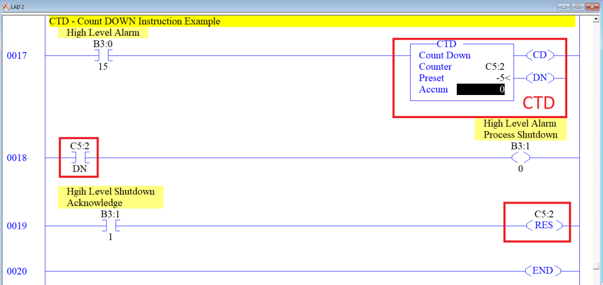
Outcome:
The CTD instruction is tied to an internal bit B3:0/15 which represents a certain alarm within the process. As the alarm is energized, the counter will decrement the value by 1. After 5 distinct alarms, the counter will reach the limit which is set at -5. Once the limit is reached, the counter will automatically set the .DN bit. This .DN bit will set a bit which represents that the process has reached an alarm threshold.
The threshold will be set HIGH until the .DN bit is energized. The only way to reset this bit is to reset the Counter. Doing so is possible through the use of the RES Instruction which will set the “Accum” value of the counter back to 0 and the .DN bit to LOW.
Data Types Allowed for CTD
The CTD leverages a specific data structure, called the Counter, present in most PLC systems.
- Counter – The high-level instruction specification of all the inner structures.
- .PRE – Integer specifying up to which value the timer will count.
- .ACC – Integer specifying the current time value of the timer.
- .CU – Boolean value which is set to HIGH when the counter is energized to count up.
- .CD – Boolean value which is set to HIGH when the counter is energized to count down.
- .DN – Boolean value which is set to HIGH when the timer is finished counting.
- .OV – Boolean value which is set to HIGH when the counter is overflown.
- Note: The overflow status signifies that the counter has reached the logical limit of 32767 and had to wrap back to the value of -32768.
- Note2: To avoid overloading the counter, make sure to program proper measures into your software.
- .UN – Boolean value which is set to HIGH when the counter is underflown.
- Note: The underflow status signifies that the counter has reached the logical limit of -32768 and had to wrap back to the value of 32767.
- Note2: To avoid overloading the counter, make sure to program proper measures into your software.
Important Notes
- Note 1 – The CTD instruction uses a counter which is specified internally to the PLC. The user may choose to set the values covered above through the PLC interface instead of working with them in the instruction. Furthermore, the CTD instruction will not display the current set of all the bits discussed above; they will be set on the PLC only.
- Note 2 – Counter may overload and cause the PLC to shut-down into a fault state. To prevent this from happening, you must monitor your counters and reset them appropriately. You can easily create a “trap” which would reset each counter as it reached the limit.
- Note 3 – Each counter must be unique to a CTU/CTD instruction. Using the same counter in multiple locations may cause performance issues. Avoid doing so by leveraging a single CTU or CTD instruction for a different set of conditions.
