PLC Programming Intermediate Instructions – CTU | Count Up

Introduction
The CTU, also known as the Count Up, instruction is used in pair with a Counter construct to count the number of LOW to HIGH transitions of the preceding logic. The CTU instruction will increment the “Accum” value each time the logic which leads into it is set to TRUE. Unline the Timer Instruction, the CTU will not keep incrementing until the rung is set to LOW and comes back to being HIGH. This critical element of ladder logic programming allows a programmer to keep track of how many products have passed a certain sensor, how many revolutions have been made by a certain motor, how many times a certain alarm was set and so on. It’s a widely used instruction which is extremely versatile and easy to work with.
The CTU instruction must be paired with a way to reset the counter through a RES Instruction.
Example & Usage of CTU
Here’s a real-world scenario of a CTU instruction:
- A Micrologix 1100 Allen Bradley PLC is used to control a process.
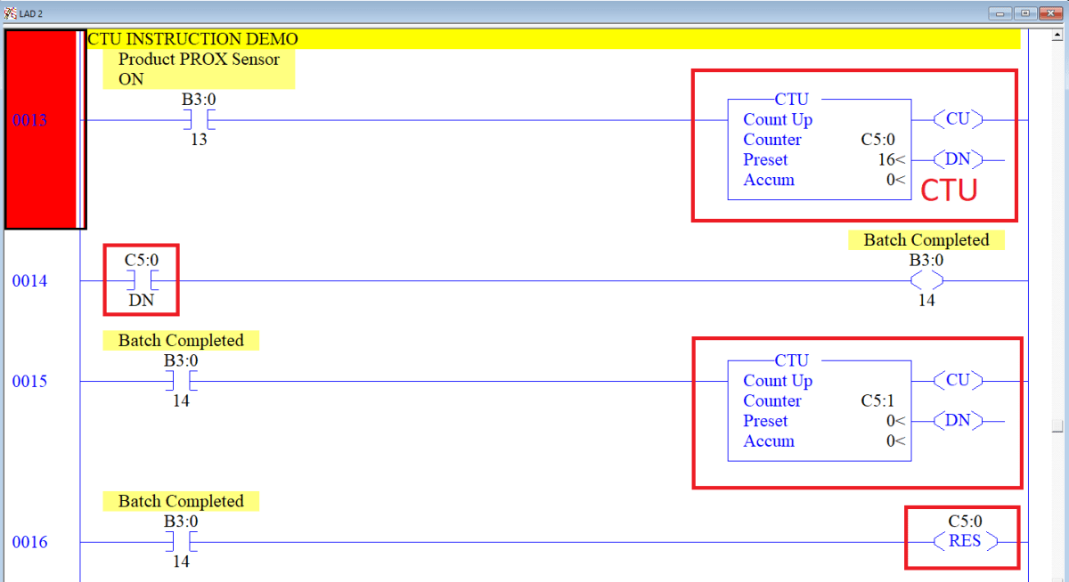
- A “Product PROC Sensor ON” is indicated by an internal bit B3:0/13.
- A CTU instruction is tied to Counter C5:0.
- The Counter C5:0 has a “Preset” of 16. The number 16 represents the number of products in a certain batch.
- When the bit B3:0/13 goes HIGH, the CTU instruction is energized and the counter increments the “Preset” value.
- When the bit B3:0/16 goes LOW, followed by HIGH, the CTU instruction is energized and the counter increments again.
- The counter will continue to increment until “Accum” = 16.
- When “Accum” of C5:0 Counter is equal to 16, the C5:0.DN bit is HIGH.
- The C5:0.DN bit is used to set an internal bit B3:0/14.
- The B3:0/14 bit is used to energize C5:1. This Counter counts how many batches have been completed.
- The B3:0/14 bit is also used to RES (Reset) the C5:0 Counter.
Programming example in RSLogix 500:
Outcome:
The CTU instruction is tied to the XIC which is energized by a proximity switch. This switch detects a certain product when it comes by on a conveyor belt. As soon as the switch detects the product, it energizes the CTU and increments the “Accum” value. This value will continue to increment every single time a new product goes by. The process will continue until the counter has reached the value of 16.
At 16, the counter will set the C5:0.DN bit because “Accum” == “Preset”. At this point, the .DN bit will set an internal bit which will energize another CTU instruction. This instruction will keep track of the batches finalized in the process. Furthermore, the .DN bit will also trigger the RES instruction which will set the “Accum” of C5:0 Counter back to 0.
The process will repeat again for each batch. Note that the counter which keeps track of the number of batches produced does not have a reset. This will need to be implemented and tied into a button which is activated at the end of a shift for example.
Data Types Allowed for CTU
The CTU leverages a specific data structure, called the Counter, present in most PLC systems.
- Counter – The high-level instruction specification of all the inner structures.
- .PRE – Integer specifying up to which value the timer will count.
- .ACC – Integer specifying the current time value of the timer.
- .CU – Boolean value which is set to HIGH when the counter is energized to count up.
- .CD – Boolean value which is set to HIGH when the counter is energized to count down.
- .DN – Boolean value which is set to HIGH when the timer is finished counting.
- .OV – Boolean value which is set to HIGH when the counter is overflown.
- Note: The overflow status signifies that the counter has reached the logical limit of 32767 and had to wrap back to the value of -32768.
- Note2: To avoid overloading the counter, make sure to program proper measures into your software.
- .UN – Boolean value which is set to HIGH when the counter is underflown.
- Note: The underflow status signifies that the counter has reached the logical limit of -32768 and had to wrap back to the value of 32767.
- Note2: To avoid overloading the counter, make sure to program proper measures into your software.
Important Notes
- Note 1 – The CTU instruction uses a counter which is specified internally to the PLC. The user may choose to set the values covered above through the PLC interface instead of working with them in the instruction. Furthermore, the CTU instruction will not display the current set of all the bits discussed above; they will be set on the PLC only.
- Note 2 – Counter may overload and cause the PLC to shut-down into a fault state. To prevent this from happening, you must monitor your counters and reset them appropriately. You can easily create a “trap” which would reset each counter as it reached the limit.
- Note 3 – Each counter must be unique to a CTU/CTD instruction. Using the same counter in multiple locations may cause performance issues. Avoid doing so by leveraging a single CTU or CTD instruction for a different set of conditions.
