PLC Programming MSG Instruction - Send Data Between MicroLogix & CompactLogix PLCs Studio 5000 Tutorial

Introduction
Sending data between two Programmable Logic Controllers can pose a challenge. However, in the current manufacturing environments, it’s an absolute must. One of the simplest ways to pass data between two controllers would be through the use of the MSG instruction. This instruction would be utilized within the RSLogix 5000 or Studio 5000 programming environments on an Allen Bradley PLC and Write or Read data from a different PLC.
For the purpose of this tutorial, we will be covering the communication between a MicroLogix 1100 PLC and a CompactLogix L24ER PLC. Both of these are heavily utilized in the current manufacturing environments and provide an excellent testing platform. Furthermore, the same instruction would work between any RSLogix/Studio 5000 and RSLogix 500 based Programmable Logic Controllers.
MSG Instruction Programming in Ladder Logic Studio 5000
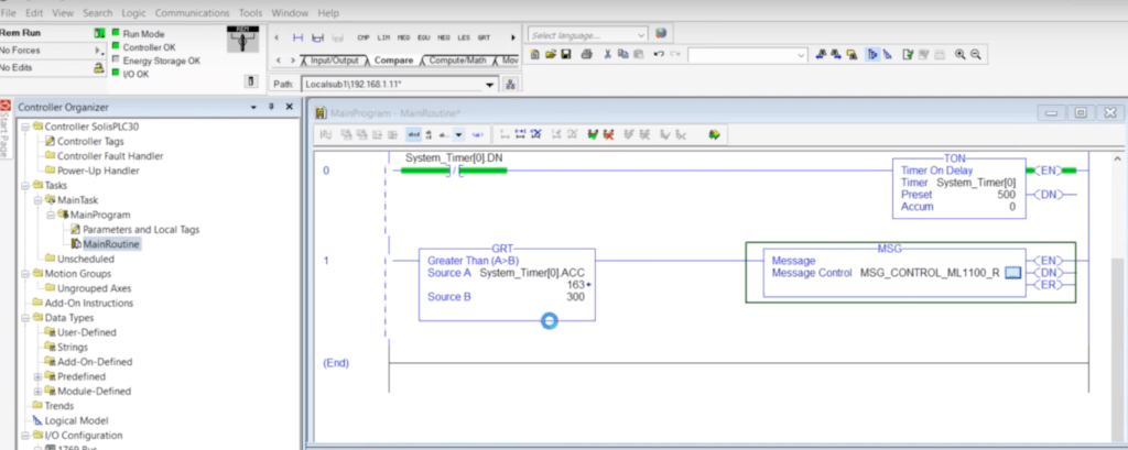
Our first step is to establish a ladder logic structure in order to accommodate the MSG instruction. In order to accomplish this, we’re going to leverage a simple repetitive timer through a TON Instruction, paired with an XIO Instruction based on the completion. This allows us to build a structure which will constantly increment the timer and reset once it reaches the peak. By using a GRT Instruction, we can trigger the MSG Instruction once per cycle of our timer.
Keep in mind that you may increase or decrease the setpoint of the timer in order to execute the MSG more or less frequently. There’s no solid requirement here, but it’s definitely recommended not to send data too frequently if it isn’t critical. Moreover, if the data is critical, it’s recommended to use alternative methods, such as Produced/Consumed tags, to get the data across.
Configuring the MSG Instruction
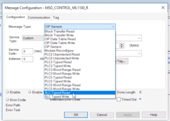
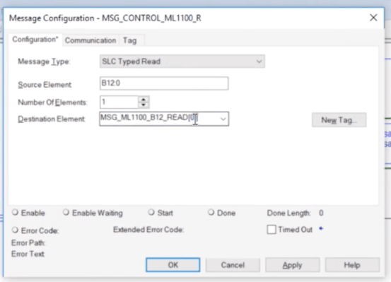
The ladder logic is an excellent start, but we’re not quite done yet. We now need to specify which tags are being read from, which tags are being written to and what the path of the communication between the devices is. By clicking the settings of the MSG instruction we access a menu which allows us to do just that. For the purpose of this tutorial, we specify that the instruction will be used as an “SLC Typed Read”, will read from the tag “B12:0” and store the data into a controller based tag “MSG_ML1100_B12_READ”. Do note that these tags are declared as arrays as we do want to make sure that the users can further expand this functionality when it’s needed.
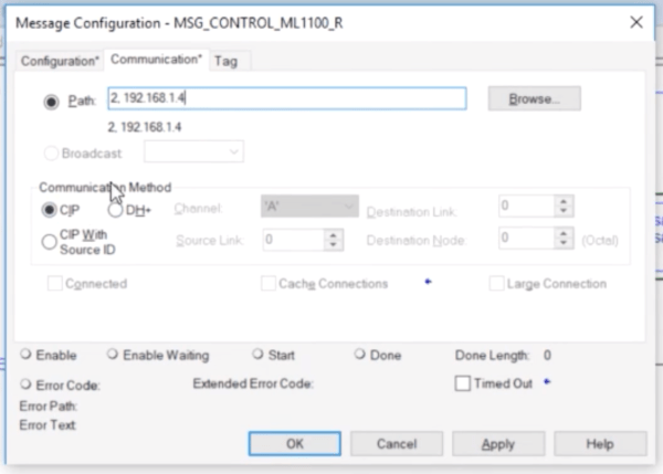
The second tab of the instruction allows us to define the path through which the PLC will send & receive packets. For an EtherNet based system, we need to input the address of the MicroLogix PLC and specify that this communication will be sent over CIP. CIP is an EtherNet based protocol which Allen Bradley utilizes for most of their hardware. The 2 which you see at the start of the path definition calls out the fact that we’re communicating over the backplane first. In other words, it’s something you always specify for CompactLogix processors and ControlLogix processors when they go through an ENxT network card.
Testing and Troubleshooting the MSG Instruction
Over the years, I’ve seen many reasons for which an MSG Instruction will fail. Just like with anything else, it’s important to know how o troubleshoot.
Step 1 – Make sure that the ladder is executing the instruction. This can be easily checked by looking at the .EN bit of the MSG Instruction.
Step 2 – Make sure that your hardware is on the same network and IP Addresses allow them to communicate. Connect your laptop to the same network & use the “ping x.x.x.x” command to check connectivity to both PLCs.
Step 3 – Make sure that the tags are in place and are correctly specified on both ends. Verify that the data types match as well. You can’t write BOOLs into REALs.
Step 4 – Verify the configuration of your instruction. You need to make sure that the instruction is set to read/write correctly and that the path is defined exactly as it’s established in the real world. If the path becomes a problem, you may add the secondary PLC into the I/O Tree of the one doing the messaging.
Conclusion
The MSG instruction provides an easy way to establish communication between two Allen Bradley PLCs. In the tutorial above, we’ve demonstrated all the steps required for creating this connection between a MicroLogix 1100 and a CompactLogix L24ER PLCs.
There are a few things you should keep in mind when using MSG instructions. The first one is that this method of sending & receiving data isn’t deterministic. In other words, the data transfer speed may be impacted by multiple factors thus making it somewhat unreliable. The second item is the fact that an MSG instruction is difficult to track. This comes into play when your control system changes and you now need to go back and redirect all the paths. It is thus advised to program all the MSG instructions within the same routine.
