PointIO Overview and Technical Design & Implementation Walkthrough

Introduction
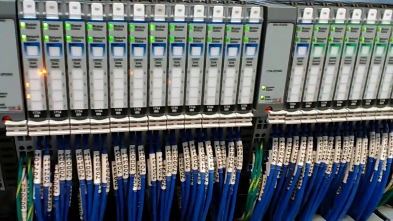
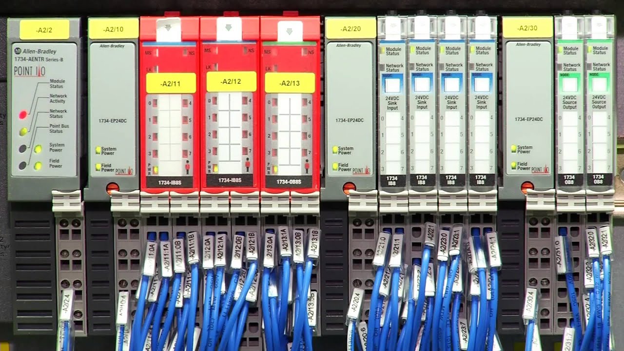
PointIO is a hardware solution from Allen Bradley that allows a PLC to extend input and output reach to remote locations over EtherNet, DeviceNet, ControlNet, and PROFIBUS. This family of hardware is commonly used in distributed systems and is paired with CompactLogix or ControlLogix controllers that would otherwise be costly to wire to remote locations. PointIO offers a wide range of modules and is highly customizable to fit the needs of the application. Furthermore, it’s easy to install and troubleshoot. A module can be replaced in a running system without the need to program, re-address, or additional setup after the system has been programmed.
PointIO is a remote module system. Therefore, it is unable to operate without the main controller. Although it is possible to interface with these modules from controllers of other brands, we recommend the CompactLogix and ControlLogix families of controllers for our customers.
In this extended tutorial, we will go over the modules, talk about the design process of a PointIO rack, and discuss the advantages of going this route.
If you’re interested in a technical tutorial on how to work with these modules, we have a class available covering a lot of these aspects: PointIO hardware Class.
PointIO Network Communication
A PointIO rack must communicate to a main PLC. As mentioned above, the PointIO hardware supports one of four commonly used Allen Bradley protocols: EtherNet, DeviceNet, ControlNet or PROFIBUS. In current control systems, we recommend that our customers select EtherNet based communication which has become much better over the last decade. However, adding modules to an existing system may lead to a preference of the other options.
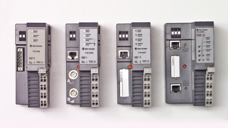
Once a protocol has been selected, it’s possible to choose a communication module that will send the data between the rack and the main controller.
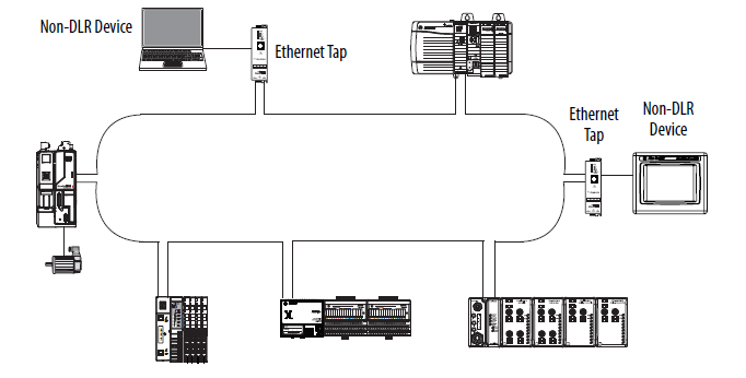
- EtherNet | The options available are 1734-AENT and 1734-AENTR. The difference in these two options is the number of ports. The AENT version has one while the AENTR has two. Furthermore, the two port option allows the PLC programmer to take advantage of dual-redundancy or Device Level Ring (DLR) network topology.
Note: we typically advise our clients to purchase the 1734-AENTR version of the communication module. The cost difference is insignificant and the EtherNet connection may be used for other field modules within the cabinet.. In other words, you may install multiple 1734-AENTR modules in the field and run one cable that would stop at every module. If you had chosen the 1734-AENT module, you would have to run a cable from the main cabinet to every module.
- ControlNet | The only option is the 1734-ACNR module. The advantage of ControlNet is that it offers reliability and is deterministic. However, this protocol is slowly being phased out as EtherNet now offers similar benefits.
- DeviceNet | Three options are available for DeviceNet communication: 1734-ADN, 1734-ADN(X), 1734-PDN. The difference between these modules lies in the specific DeviceNet infrastructure the user is seeking to achieve. In DeviceNet, every node must have a unique address and communicate based on the scheme established by the PLC programmer. It is possible to extend the network through the use of the 1734-ADN(X) module that will establish nodes on a DeviceNet subnet.
- PROFIBUS | The only option available is the 1734-APB base.
As mentioned above, every PointIO rack is essentially a “slave” to a master PLC rack. It is important to understand how to create an efficient network layout for your specific application. We recommend that your PointIO racks remain on a private subnet that is only shared with other field devices and the “master” PLC rack.
PointIO Input and Output Hardware Selection
PointIO is highly versatile and provides a wide array of modules one can use for field inputs and outputs. In this section, we will take a look at common choices and discuss why we may pick one module over another.
General Selection Guidelines
- We typically recommend the “higher-count” versions of each I/O card. In other words, if you must choose between a card that has 2 or 4 of the same input type, we typically specify the 4 input one. The reason is that the system remains compact while providing a higher number of points to connect to. If your system requires less inputs, the spares are always nice to have in case of a failure. Furthermore, note that the cost becomes lower on a per input basis when specifying this way.
- We recommend standardizing certain types of modules for a single application and the facility. Doing so will reduce costs of maintaining spare parts and make it easier for maintenance personnel to replace the modules in case of failure.
- Refer to “Point 2” when it comes to choosing your I/O scheme. In other words, it is preferable to keep all the modules the same as much as possible when it comes to PNP vs NPN, sink vs source as well as type of analog signal. Note that PointIO doesn’t provide configurable analog I/O similar to what you may find in a 1756-IF8 analog input card. The inputs can be of voltage or current type, but not both in the same card due to size limitations.
Digital AC Input Modules
When it comes to AC vs DC based signals, we typically don't have an option. In other words, our devices will either supply a feedback signal of 110VAC or 24VDC. Therefore, we will need the appropriate input or output card to accommodate them. When there is a choice, we always recommend 24VDC. These voltage levels are safer, don't require Personal Protective Equipment (PPE) when troubleshooting and are just as reliable as their 110VAC counterpart.
- 1734-IA2 | Two 110VAC digital inputs card.
- 1734-IA4 | Four 110VAC digital inputs card.
- 1734-IM2 | Two 220VAC digital inputs card.
- 1734-IM4 | Four 220VAC digital inputs card.
Step 1 - Determine the voltage of the system (110VAC vs 220VAC)
Step 2 (preferable) - Select 1734-IA2 OR 1734-IM4.
Digital AC Output Modules
- 1734-OA2 | Two 110VAC or 220VAC digital outputs card.
- 1734-OA4 | Four 110VAC or 220VAC digital outputs card.
Step 1 (preferable) - Select 1734-OA4.
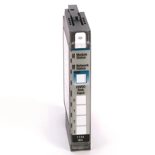
Digital DC Input Modules - Sinking
A sinking input module would draw current from the device it is connected to. This scheme is commonly found in North America and is paired with PNP sensors and other field devices. If you’re building machinery or plant equipment for a North American plant, we highly recommend that you standardize on sinking input modules.
- 1734-IB2 | Two 24VDC digital sinking inputs card.
- 1734-IB4 | Four 24VDC digital sinking inputs card.
- 1734-IB4D | Four 24VDC digital sinking inputs card with diagnostics.
- 1734-IB8 | Eight 24VDC digital sinking inputs card.
Since every PointIO terminal base allows for 8 wiring points, the two and four input cards will have their own common signals available. The 8-point card will require a connection to a common terminal block that may be adjacent to the PointIO rack. In our case, we typically provide a large common access point for the 24VDC and 0VDC signals on the side of every PointIO rack.
Step 1 (preferable) - Select 1734-IB8.
Digital DC Input Modules - Sourcing
A sourcing input module would output current to the device connected to it. This scheme is commonly found in Europe and is paired with NPN sensors and other field devices. If you’re building machinery or plant equipment for a European plant, we highly recommend that you standardize on sourcing input modules.
- 1734-IV2 | Two 24VDC digital sourcing inputs card.
- 1734-IV4 | Four 24VDC digital sourcing inputs card.
- 1734-IV8 | Eight 24VDC digital sourcing inputs card.
Step 1 (preferable) - Select 1734-IV8.
Digital DC Output Modules - Sourcing
Note that sinking inputs are most commonly paired with sourcing outputs. In other words, you’ll typically find sourcing output PointIO modules in North America. We recommend that you standardize as such if you’re working on or building equipment in this region.
- 1734-OB2 | Two 24VDC digital sourcing inputs card.
- 1734-OB2E | Two 24VDC digital sourcing outputs card with diagnostics.
- 1734-OB2EP | Two 24VDC digital sourcing outputs card with diagnostics and high-current channel capability.
- 1734-OB4 | Four 24VDC digital sourcing outputs card.
- 1734-OB4E | Four 24VDC digital sourcing outputs card with diagnostics.
- 1734-OB8 | Eight 24VDC digital sourcing outputs card.
- 1734-OB8E | Eight 24VDC digital sourcing outputs card with diagnostics.
Due to the availability of an 8-point output module with diagnostics, we recommend choosing it. Note that on the input side, the 8-point module did not have a version that would provide diagnostics.
Step 1 - If your application requires 4A of current, select 1734-OB2EP modules.
Step 2 (preferable) - Select 1734-OB8E OR 1734-OB8 based on price constraints.
Digital DC Output Modules - Sinking
Note that sourcing outputs are most commonly paired with sinking inputs. In other words, you’ll typically find sinking output PointIO modules in Europe. We recommend that you standardize as such if you’re working on or building equipment in this region.
- 1734-OV2E | Two 24VDC digital sinking outputs card with diagnostics.
- 1734-OB4E | Four 24VDC digital sinking outputs card with diagnostics.
- 1734-OB8E | Eight 24VDC digital sinking outputs card with diagnostics.
Due to the availability of an 8-point output module with diagnostics, we recommend choosing it. Note that on the input side, the 8-point module did not have a version that would provide diagnostics.
Step 1 (preferable) - Select the 1734-OB8E module.
Digital Contact Modules
A contact module will contain relays that will be opened or closed depending on their initial state and the signal sent to the card. These modules have two main disadvantages: a mechanical relay would typically fail much quicker than a solid state circuit and a mechanical relay contact is much slower to close and open. However, these contacts conduct a much higher current and can accommodate signals of different voltages. Our role of thumb is to specify solid state input and output modules for our clients, unless there’s an application with high current loads: valves, actuators, etc.
- 1734-OW2 | Two Normally Open Relay output card.
- 1734-OW4 | Four Normally Open Relay output card.
- 1734-OX2 | Two Normally Open / Closed Relay output card.
Step 1 (preferable) - Select the 1734-OW4 module.
Analog Input Modules
Analog modules are of current or voltage type. It is important to confirm which devices will be tied to these in order to properly specify them in the PointIO architecture. If it’s possible to standardize, we recommend our clients to purchase the 4-20mA modules. A 4-20mA signal would provide an additional feedback at 0mA when the device is not connected or is defective. In the case of a voltage signal, 0V can be a standard value.
- 1734-IE2C | Two current input card.
- 1734-IE2V | Two voltage input card.
- 1734-IE4C | Four current input card.
- 1734-IE8C | Eight current input card.
The current input module provides a larger array of inputs available (up to 8). Furthermore, as mentioned above, a current signal is typically preferable over a voltage one. Therefore, we recommend that you choose the 1734-IE8C module for your analog needs unless your field device is only capable of transmitting a voltage signal.
Step 1 (preferable) - Select the 1734-IE8C module.
Analog Output Modules
An analog output can be used to control the position of a valve, the speed of a motor or any other device with a variable setpoint.
- 1734-OE2C | Two current output card.
- 1734-OE2V | Two voltage output card.
- 1734-OE4C | Four current output card.
Step 1 (preferable) - Select the 1734-OE4C module.
Specialty PointIO Modules
The list of modules above is non-exhaustive. PointIO provides solutions for temperature probes, various communication protocols, configurable input and output modules and safety based hardware. Although we recommend that you explore those modules depending on your application, the modules listed above should cover 90% of projects.
PointIO Terminal Base Selection
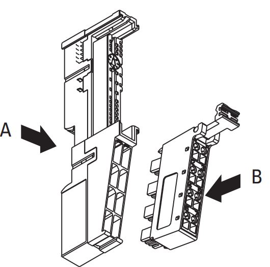
Every module must be set on a base. The base will clip onto a din-rail inside of an electrical panel and host the PointIO module on the front side. Furthermore, the terminal base will conduct signals between other bases and the network connector that will be tied to the leftmost base within a PointIO rack.
It’s important to note that a module may require one of two different types of bases. Certain modules have an 8-pin breakout and require a base of type 1734-TB, 1734-TBS or 1734-TOPS. The 12-pin cards will require a terminal base of type 1734-TB3, 1734-TB3S, 1734-TOPS or 1734-TOP3S.
Each one of the terminal bases will be paired with a wiring terminal block that provides the interface for the I/O. This interface can be of spring-clamp or screw-clamp style. Although there is no definite advantage of one over the other, we recommend that you standardize on a certain type of terminals in your facility or machine. Based on our experience, electricians prefer the screw-clamp style due to their durability over time.
PointIO Power Supply Unit Selection
Just like with any other control system hardware, power is required to drive the inputs and outputs in the PointIO family. Although the network adapter (ex: 1734-AENTR) will supply power to the IO cards, it’s common to install additional power supply units within every PointIO rack.
To calculate the power requirements of your specific rack, you need to add all the currents supplied by your modules. Once that’s done, you need to satisfy the requirement through a combination of the network adapter and additional power supplies in the rack.
In addition to supplying the necessary power to the modules, power supply units in the PointIO family will provide a physical isolation of the power bus between the cards. This is important as you may limit power faults that may be caused by modules of different types.
- 1734-EP24DC | 24VDC Input Power Supply Unit.
- 1734-EPAC | 110-220VAC Input Power Supply Unit.
You may select either option listed above. However, we tend to maintain consistency between our devices and have a preference for the 24VDC units. Furthermore, this keeps our control system cabinets touch-safe which does not require Personal Protective Equipment (PPE) when working on them.
Separation of Logic Cards
We design our PointIO racks with different signals in mind: digital, analog, relay, 110VAC vs 24VDC. Therefore, we tend to divide these areas using power supply units. For example, the low voltage input cards would be followed by a power supply. Next, we have our analog signals that are driven by input and output cards followed by a power supply. Lastly, the higher voltage cards would also be broken off by a power supply unit.
Conclusion on PointIO
PointIO provides a series of hardware solutions that allow a control system to place inputs and outputs closer to field equipment. This provides cost savings by eliminating wiring and allows a PLC programmer to design a distributed system that will leverage a single primary controller.
