PowerFlex 525 Parameter, Input and Output Programming Tutorial in RSLogix Studio 5000

PowerFlex 525 Introduction
The PowerFlex 525 series of Variable Frequency Drives from Allen Bradley is highly utilized and respected within the automation field. The drives are compact, versatile and easy to use. We’ve written an extensive tutorial on how to get started with these drives in a previous tutorial; it covers how to initialize the drive, connect it to an EtherNet/IP based PLC and how to set the right parameters.
View Tutorial - PowerFlex 525 VFD Setup Tutorial
In this tutorial, we’re looking to expand on the concepts and demonstrate a way to access and utilize the multiple Input and Output options available on the drive.
The reason you may want to utilize the IO is to save money on purchasing external components, integrate instrumentation into your drive and save floor space, wiring and cost. We’ve seen the need to integrate closely related sensors into a PowerFlex 525 application; this would be the right way to do it.
PowerFlex 525 - Supporting Documents
PowerFlex 525 Datasheet Part 1/2 Download
PowerFlex 525 Datasheet Part 2/2 Download
PowerFlex 525 Available Inputs and Outputs
The PowerFlex 525 series variable frequency drive provides an array of I/O points that are summarized in the datasheet drawing below.
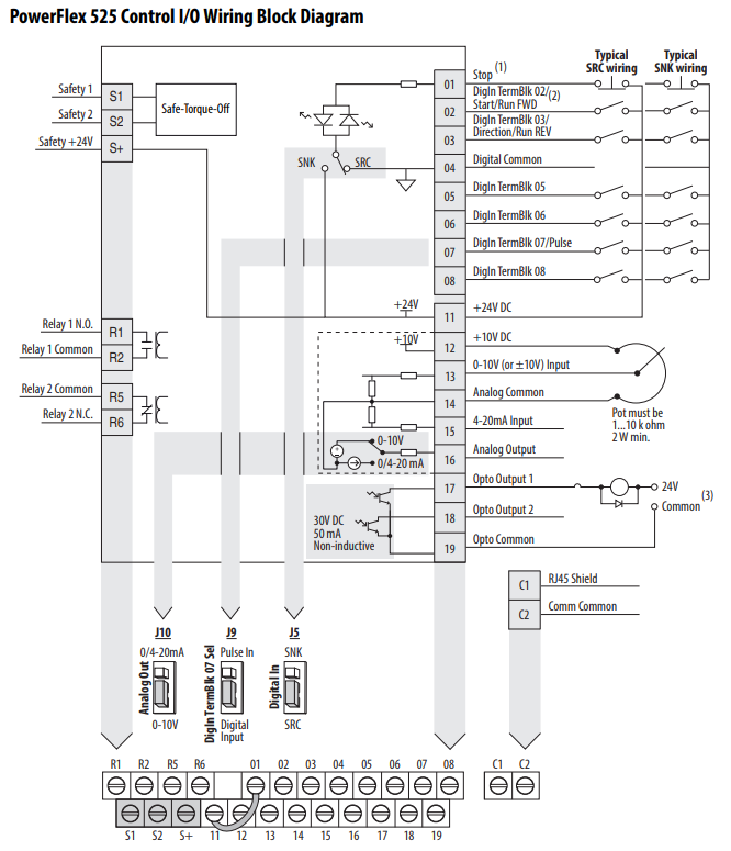
From this drawing, we can identify the following elements:
PowerFlex 525 Inputs
- 7 x Digital Inputs
- 2 x Analog Inputs
PowerFlex 525 Outputs
- 1x Analog Output
- 2 x Opto-Isolated Outputs
- 2 x Relay Outputs
The IO points on the PowerFlex 525 are tied to a certain function by default. Furthermore, each point can be configured to a series of functions. Therefore, it is confusing to get these configurations right the first time you work on such a solution. Our goal is to walk you through the process, explain the parameters we’re setting and give you the step-by-step path to getting them setup on your system.
For example purposes, we will be utilizing a single digital input point and a relay output. It’s important to note that you can set up the other points using the same steps, but the settings will differ.
PowerFlex 525 - Hardware Wiring
We start by wiring the relay output. We’ll need to take care of the following constraints:
- We must draw +24VDC and -24VDC signals directly from the drive.
- The LED is polarized. We can switch the +24VDC signal through the relay or the -24VDC signal.
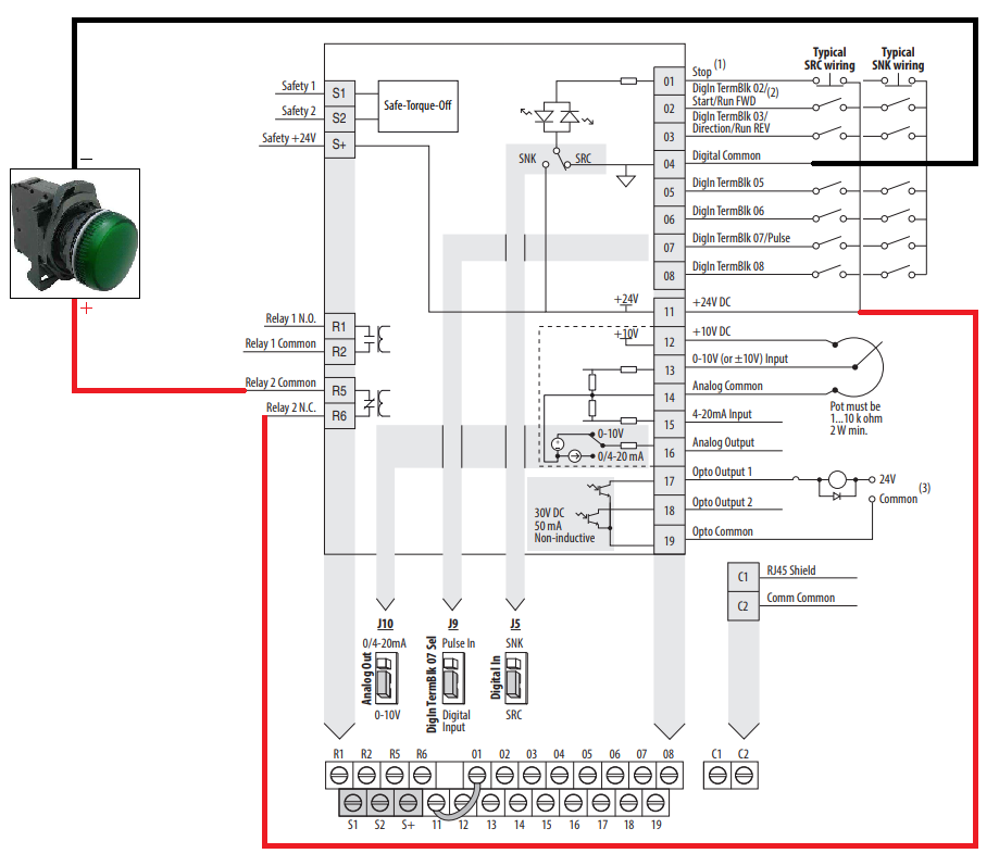
As shown above, we can draw the +24VDC signal directly from the drive terminal 11. This terminal will always provide this signal. It’s important to note that this terminal is internally tied to the S+ terminal which is used for safety circuits.
The -24VDC signal can be drawn from terminal 04 labeled as “Digital Common”. However, the polarity of this terminal will depend on the PCB jumper J5. The default setting of the jumper is “SRC” which leads the signal to be tied to the ground. Should the jumper J5 be set to SNK, the terminal would be tied to +24VDC. It is important to pay attention to this setting as the output switching will not work if there’s no -24VDC signal. As an alternative, this may be drawn from an external power supply.
We will utilize a normally open (NO) push-button as the demonstration of the input signal. We have the following constraints:
- The push button must toggle a digital input.
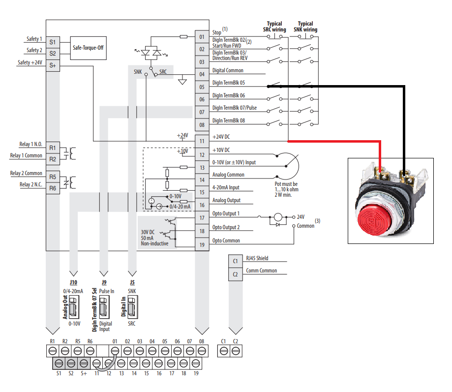
As shown above, the push-button circuit is straightforward. We’re using the +24VDC contact on the drive pin 11, sending the signal through the contact and tying the other side to the “DigIn TermBlk 05”. While the contact is open, the terminal should read a LOW. When it is closed, the terminal will read HIGH.
PowerFlex 525 - Setting Parameters
Now that we have the circuits in place, we need to find the right parameters and configure them to the appropriate setpoints. We start by looking at the datasheet; we can use the “Ctrl+F” command to search for “relay” or “digital input”.
Relay Output Settings
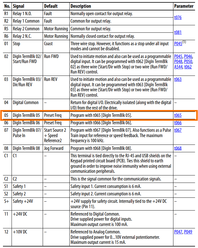
Using the “relay” search and by scrolling through the results, we find the following table that indicates a starting point to configure the relay output.
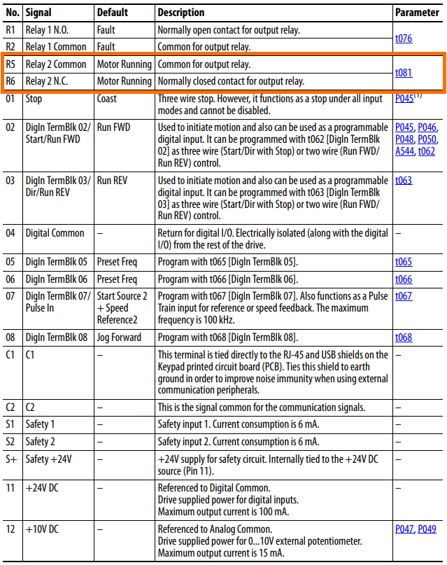
Within the table above, we identify several important items:
- The Relay 2 terminals are R5 and R6 (as we had identified during the wiring step).
- The Relay 2 default function is “Motor Running”. We’ll have to change that.
- The Relay 2 Parameter reference is “t081”.
The parameter reference is especially important to us, as we need to change the signal the relay responds to. By clicking the reference within the pdf file, we are brought directly to the following page.
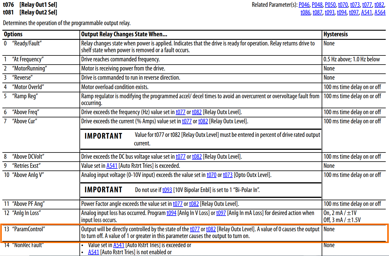
Within the table above, we find all the settings that we can set “t076” and “t081” parameters to.
Note 1: The image above represents a portion of the table; additional settings are available.
Note 2: The table shows parameters for Relay 1 and Relay 2. It’s important to distinguish between the two depending on the application.
By reading the “Output Relay Changes State When…” portion of the table, the user can determine which parameter to use for their specific application. In our case, we’re looking to control the relay through software. Therefore, we need to set the parameter to “ParamControl” or 13.
Note 3: The table indicates that the relay will be controlled through “t077” and “t082”. Per Note 2 above, we must utilize “t082” as we are interested in Relay 2.
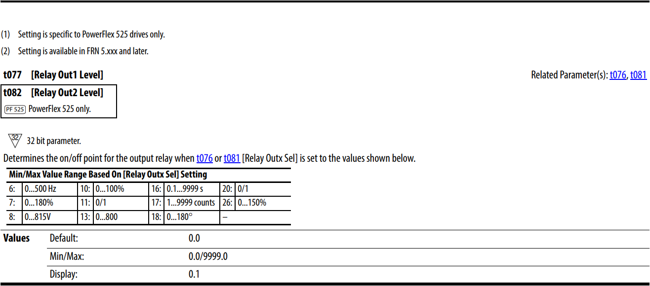
Once again, we can click the “t082” parameter and be brought to the appropriate settings page. However, the application is self-explanatory within the table above; we need to set this parameter to 0 or 1.
Digital Input Settings
Similarly to the relay, we can search for a digital input. We quickly stumble on the following table.
In this case, we notice that the default setting for the digital input is “Prser Freq”. By using “t065”, we can change the function of the input.
By clicking on the parameter, we’re brought to the following table.
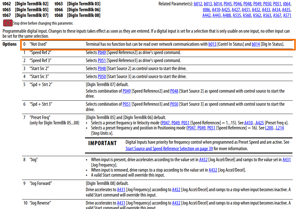
Within the table above, we first notice that the settings affect all digital terminals.
Note 1: The drive must be stopped before changing these settings as indicated above the table.
Note 2: The image above represents a portion of the table; additional settings are available.
We need to set our parameter to “Not Used” or 0. This setting will allow us to read the digital input directly through the “b013” and “b014” registers.
PowerFlex 525 - Studio 5000 Settings
Now that we have identified the parameters we need to work with, it’s time to open Studio 5000 and begin the configuration of the drive.
Step 1 - Setting Relay Output Settings
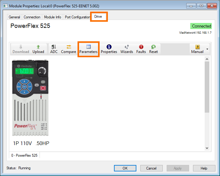
Step 1.1 - Open the PowerFlex 525 Drive Parameters
Step 1.2 - Navigate to the “Drive” Tab
Step 1.3 - Open “Parameters”
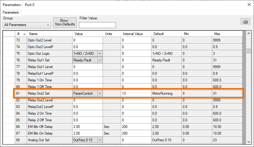
Step 1.4 - Change Parameter 81 Value to “ParamControl” or Internal Value to 13.
Step 2 - Setting Digital Input Settings
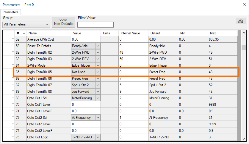
Step 2.1 - Change Parameter 65 Value to “Not Used” or Internal Value to 0
Step 3 - Setting Software Input/Output connections to/from PowerFlex 525
As discussed above, we need to set and read certain parameters of the drive in order to toggle the relay and read the status of the input. This is achieved by changing the “Module Definition” of the drive. It’s important to note that these values are not set by default. Therefore, there is no reason to read or set these parameters without going through the following steps.
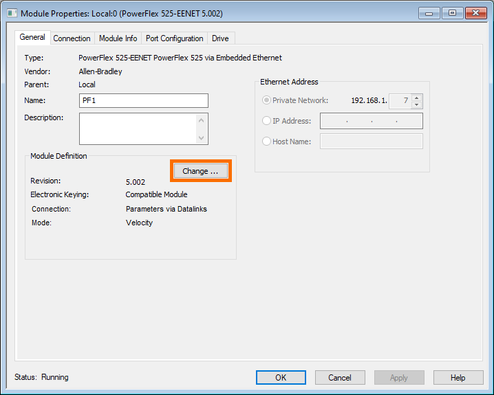
Step 3.1 - Save the Program and Go Offline
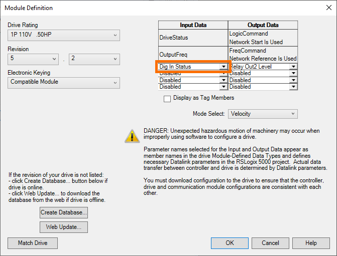
Step 3.2 - Open the “Module” Definition of the PowerFlex 525
Step 3.3 - For “Input Data” Choose “Dig In Status”
The “Dig In Status” is the parameter that holds the status of the digital input we have tied our push-button to. By having this parameter in the “Input Data” section, the drive will send the appropriate information to the PLC.
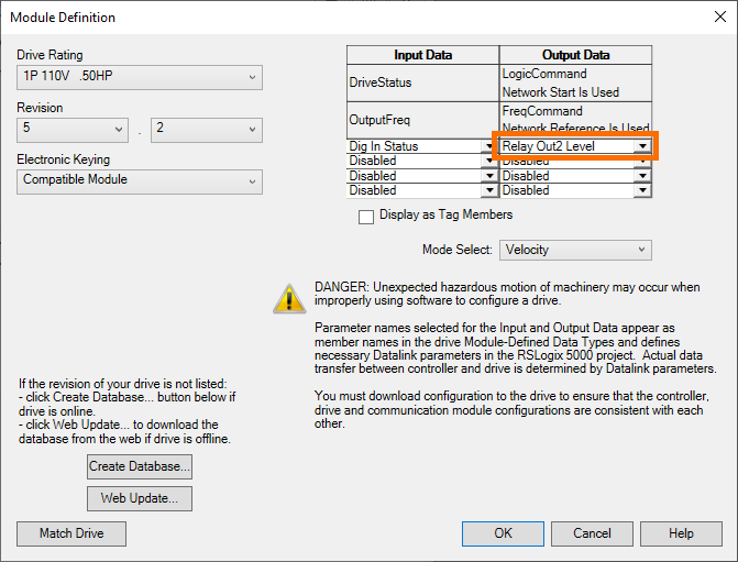
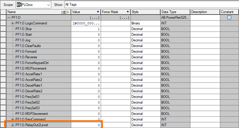
Step 3.4 - For “Output Data” Choose “Relay Out2 Level”
The “Relay Out2 Level” parameter will be used to set the status of the relay.
Step 3.5 - Go Online and Download the Program
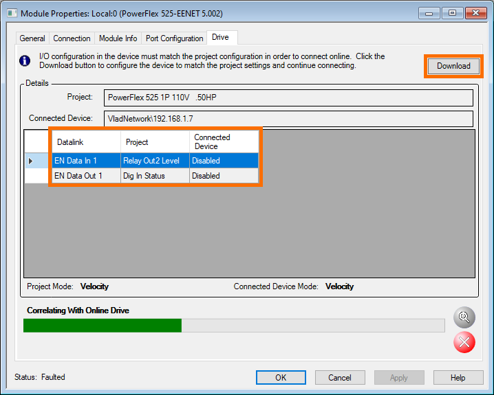
Step 3.6 - Download the Configuration to the VFD
Once you download the new PLC Program, the drive will go into a faulted state. The reason for that is the fact that we’ve changed the definition of the data flow which resides on the drive. In other words, the PLC is expecting certain data values to be passed to and from the drive, while the drive isn’t set to produce those data points.
To remedy the state above, navigate to the “Drive” tab of the PowerFlex 525 drive and press the “Download” button. This action will send the updates made on the PLC side to the drive and clear the fault.
PowerFlex 525 - Utilizing the I/O in Ladder Logic PLC Programming
Now that we’ve configured the I/O and parameters of the drive, how do we utilize them?
By going to the PLC tags, we can find the new structures we’ve sent to and from the drive. It’s important to note that these tags are dynamic and aren’t available in the default AOI configuration of the PowerFlex. They will change according to what you add in “Step 3” above.
In order to read the status of the digital input we’ve connected, use the following tag within the definition:
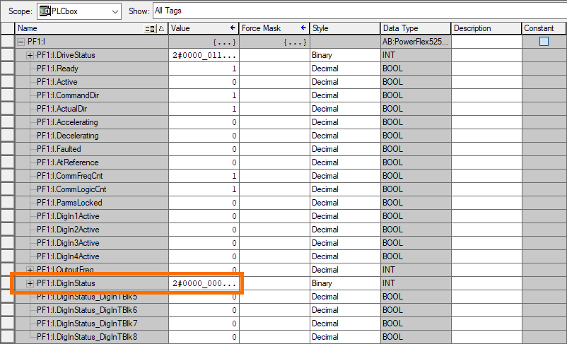
In order to get the status of the terminal block that we have connected the push-button to, we turn once again to the datasheet. The parameter we’ve mapped has the following definition:
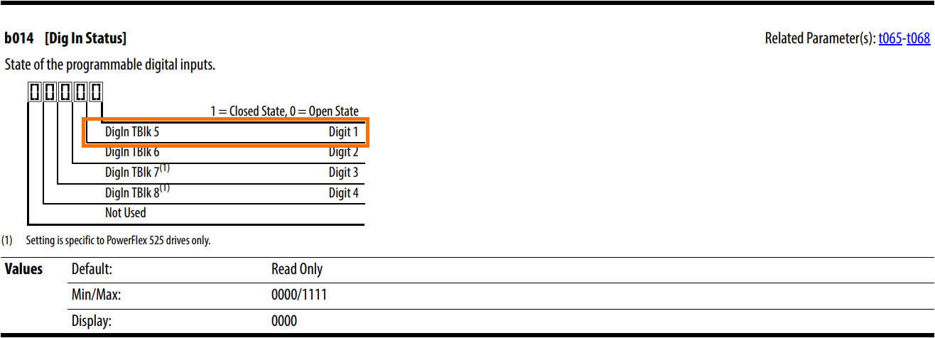
Therefore, we conclude that the input will toggle the first bit of the PF1:I.DigInStatus shown above.
To control the relay, we’ll have to set a tag within the output section of the PowerFlex. We’ve defined an output and the following tag was added to the structure:
What do we set this value to? Per the datasheet below, the relay will be closed when the value is 0 and open when it’s anything else.
We can thus create a simple rung that would activate the relay based on the status of the input as follows:
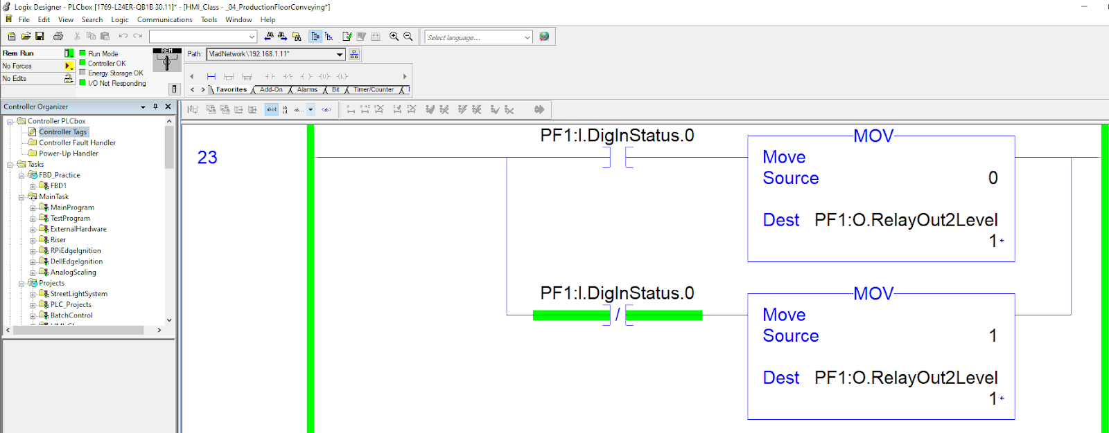
Note 1: The relay is toggled by writing a “0” OR “Anything Else”. Although we can toggle the first bit of the integer, we’d open the possibility of losing control of the relay. Therefore, we’d prefer the MOV instruction that will ensure that the integer is set back to 0.
The logic above is the simplest utilization of these two points of O/I; it can be utilized for much more complex means.
Frequently Asked Questions about the PowerFlex 525 Variable Frequency Drive (VFD)
What is PowerFlex 525 used for?
The PowerFlex 525 VFD is used to control a variety of motors - induction, permanent magnet, and synchronous reluctance. These motors are tied to different mechanical assemblies on the plant floor - pumps, fans, conveyors, gearboxes, etc.
Does PowerFlex 525 have EtherNet?
The PowerFlex 525 Allen Bradley VFDs can be started, stopped, and controlled using different channels - hard wired, analog signals, EtherNet/IP, DeviceNet, etc. At this time, EtherNet/IP is the preferred method as it's flexible, easy to deploy, and provides a level of control we didn't have over digital / analog IO. By Using EtherNet/IP as the protocol, control systems engineers deploy an architecture that has full control over the drives via a single cable and provides them with data that can be used for troubleshooting purposes (ex: torque, voltage, current, status, etc.).
.png)
How do I change the parameters on my PowerFlex 525?
There are three ways to change the parameters of a PowerFlex 525 Allen Bradley drive. The easiest way, without additional software, is to use the front panel buttons of the drive. By navigating the menu via the push-buttons on the faceplate, it's possible to modify every parameter of the drive. The second approach is by using RSLogix / Studio 5000 software - programmers can connect to the drive and make changes to the parameters as needed. Lastly, PowerFlex 525 drives are compatible with CCW, or Connected Components Workbench, a free tool from Rockwell Automation that can be used to connect directly to a drive, create a backup, load a file, and to change the parameters. Note that CCW is also the tool used to program the Micro800 series PLCs, so if your facility is using those it's an excellent choice for managing PowerFlex 525 drives.
How do I check my Powerflex 525 revision?
Every piece of Allen Bradley hardware has a specific firmware revision. An engineer, or technician, can view the revision of a device through some of the tools - RSLinx, RSLogix, Studio 5000, etc. It's important to note that if you desire to upgrade the firmware of your drive, you'll need to install ControlFLASH which is a tool you can download directly from Rockwell. In addition to ControlFLASH, you'll need to download the firmware which is also available on the Rockwell website. Note that we always advise to validate the changes that will come with a new revision as there can be compatibility issues with the hardware your drive is connected to. You can find this information on the official PowerFlex 525 documentation for a specific part number you have in place.
PowerFlex 525 - Conclusion on On-Board I/O
The PowerFlex 525 Variable Frequency Drive is widely utilized within the field. This drive features a number of Input and Output ports for various applications. By setting specific parameters of the drive, a PLC programmer can take advantage of these features and save on field I/O. In this tutorial we’ve demonstrated the use of an on-board digital input and a relay output. The procedure would be similar to other I/O points available.
In conclusion, the PowerFlex 525 Variable Frequency Drive stands out as a versatile and widely embraced solution in the automation realm. The drive's compact design, ease of use, and robust features make it a preferred choice for controlling a range of motors and applications. This tutorial has delved into the intricate aspects of leveraging the PowerFlex 525's Input and Output options effectively. By providing a comprehensive walkthrough, we have empowered users to harness the multiple I/O points available on the drive, facilitating cost savings, streamlined integration of instrumentation, and optimization of floor space.
The exploration of digital inputs, analog outputs, and relay outputs has been exemplified through a detailed guide, emphasizing the importance of meticulous parameter configuration. From hardware wiring to software settings in Studio 5000, we've navigated the intricacies, ensuring a thorough understanding of the PowerFlex 525's capabilities. As demonstrated with a focus on a digital input and relay output, the tutorial encourages users to extrapolate these insights to other I/O points, fostering adaptability to diverse applications. The integration of ladder logic PLC programming serves as a practical illustration, showcasing how to implement these configurations seamlessly. In essence, this tutorial serves as a valuable resource for both beginners and seasoned professionals, offering a clear roadmap to unlock the full potential of the PowerFlex 525's on-board I/O capabilities. As industries evolve, this knowledge becomes a powerful tool for efficiency, resource optimization, and innovative automation solutions.
