Sending Data from a MicroLogix or SLC PLC to a CompactLogix PLC Using the MSG Instruction

Introduction
Sometimes we need to send “running” or “stopped” status from one machine to another. In other cases, we need data about the shop air pressure or flow rate from the compressor control system used as a variable into our control logic of our machine. Other times it might just be more convenient to wire a new sensor or output device to a PLC that is physically located closer to the end device than the PLC that will actually be using that IO for logic in a program.
Whatever the use case is, in modern controls systems having the skills to be able to push or pull data from one PLC to another can be a time and cost saver. Besides, with a little networking knowledge and a few rungs of code, it can be an easy skill to master!
By the time you complete this tutorial, you will have the skills necessary to move data back and forth from a MicroLogix or SLC PLC to a CompactLogix PLC.
Prerequisites
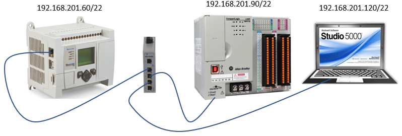
The hardware we will be using a MicroLogix 1100 Series B with V14 firmware communicating with a CompactLogix L24ER-QBFC1B with V24 firmware.
This same method will work using any RSLogix 500 based PLC to any RSLogix or Studio 5000 based PLC with very little to no changes at all.
Software used will be RSLogix 500 Version 10 and Studio 5000 Version 24, but again, any version could be used with minimal changes.
The last piece that we need to this puzzle is a network switch so that all devices can be physically connected. Along with that is a logical network configured so that all devices are on the same subnet and can communicate together.
A little history lesson
We need to understand that the MicroLogix is a 16-bit address-based PLC and that the CompactLogix is a 32-bit tag-based PLC, so there are some incompatibilities there we will have to deal with as we go. The other thing we need to know is that the MicroLogix was “born” before the CompactLogix was introduced; therefore, it has no idea that the CompactLogix exists. But the CompactLogix knows that the MicroLogix exists.
Building the MSG logic in RSLogix 500
We will start in the RSLogix 500 software for the MicroLogix 1100 PLC.
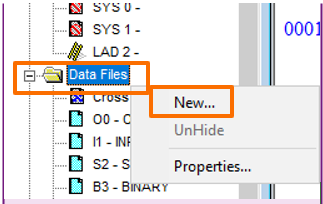
Because we are expanding the functionality of what our project can do, we need to start building some new data tables to hold that data we will be working with. To do so, right-click on “Data Files” in the project tree and click “New”.
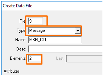
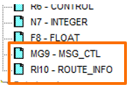
Next, you will create a new MESSAGE data table. Leaving the file number at 9, make sure you select Message for the type. We will be making two MSG instructions, so we will have to create it with two or more elements. We can always add more if we need them. Optionally, you can give it a name.
We need to create another new data table for routing information using the same steps as above with just a little different information.
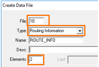
You will end up with these two additional data tables.
We will make two rungs that will be nearlyidentical. The outputs of these two will be the messaging instructions. Since there is a process the messaging instruction needs to go through, it cannot be held true all the time. We will have to make the input side of our rung strobe on and off at a set rate.
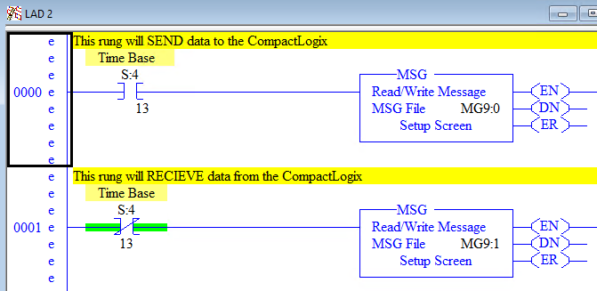
We will use the S:4/13 bit as the trigger for the MSG. This is a system bit that is true for roughly one second and false for roughly one second. That should be plenty of ON time for the instruction to get done with its process, yet still giving us some off time. If we need any faster or slower rate, we can simply increase or decrease the bit identifier (13). One rung will operate when the bit is true the other will operate when the bit is false.
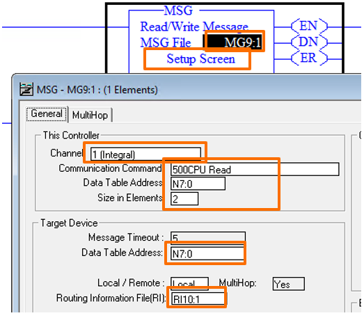
Now we will set up our Message instructions.
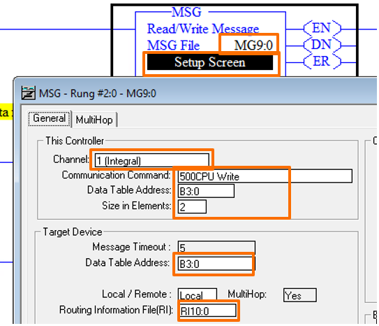
Set the MSG File to MG9:0. All this does is give this instruction someplace to keep track of all the information for itself. Then click on the Setup Screen.
The Channel is the way it will communicate out of this PLC. Channel 1 on this PLC is the Ethernet port whereas channel 0 is the serial port. The communication command is the method we will use to talk to the other PLC. Just remember that this PLC does not know how to directly talk to a CompactLogix. We will take care of that at the other end. Data table address is the data in this case that we are going to send. Size in elements is how many 16-bit words we are going to send starting at B3:0. So we will send both words B3:0 and B3:1 to the other PLC. This will match up with the Target Device – Data Table Address that we have set for B3:0. Last for this screen is the Routing Information File. We set that to RI10:0. Again, this just gives this part of the instruction someplace to hold the information about how exactly we communicate to the other PLC.
Now we must set up the MuiltHop tab.
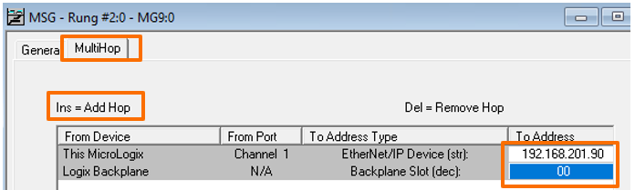
This screen is a little tricky. The first line is easy, we just simply add the IP address of the PLC we want to communicate to. The second line will not appear until you press the Insert on your keyboard. Then this is the slot number on the Logix backplane that contains the processor - on CompactLogix, this is always 00. You can close out of this screen, and we will now need to configure the second rung.
Most things here are the same except that we are going to do a 500CPU Read here and use N7:0 as our addresses. The MultiHop setup will be the same.
You are now ready to download this to your MicroLogix PLC. However, when you run the MSG instructions, you will most likely get an error, but that is alright, that is just because we have not configured the CompactLogix PLC to listen to the messages yet. That is next!
Setting up the CompactLogix PLC
Once a new program in Studio5000 is created, the first thing we will have to do is create some controller tags to store the data that we will be sending and receiving from the MicroLogix.
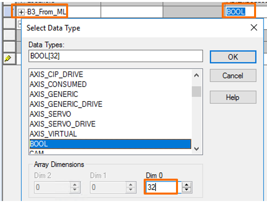
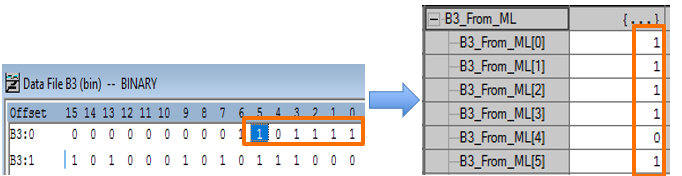
Here we will create a new tag and we will call it B3_From_ML. Make sure to set the Data Type to BOOL to match the type that the MicroLogix is capable of sending. We are also sending 32 bits with the two words of data so we will have to set Dim 0 to the value of 32 so we will have 32 bits here to store it in.
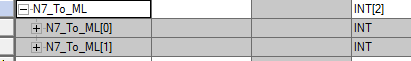
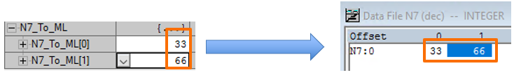
Now again for a tag called N7_To_ML. Make sure to set the Data Type to INT to match the 16-bit integer type that the MicroLogix is capable of sending. Here our Dim 0 will have to be set to 2. We end up with the following:
Almost done! Now from the menu at the top click on Logic then:
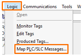
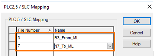
Here is where we tie it all together. Messages from the MicroLogix will communicate with this added feature on the CompactLogix. When the message arrives to the Compact, it is as a file with a number attached to it. The CompactLogix will see that file number and map it to the tag we have specified in this list. This is how we get an address based PLC to communicate with a tag based PLC. So, all we have to do is line them up.
Now, download that into the CompactLogix and put the controller into run mode. That’s right, we don’t need to have any rungs of code for this to work if we type values into the Compact N7_To_ML tag it will show up in the MicroLogix N7 registers.
Also, if we change the values in the MicroLogix B3 registers it will move them to the CompactLogix B3_From_ML tag.
Remember that we are only moving data one way. We write to the CompactLogix from the B3 and read from it with the N7. Therefore, if we put a value in N7, it will be overwritten by the value that is in N7_To_ML in the CompactLogix the next time the MSG command is true. The same will happen with the B3_From_ML tag. If we change that value in the CompactLogix it will be overwritten by the value coming from the MicroLogix.
Conclusion
You have now successfully configured the MSG instruction with only two rungs of code in the MicroLogix and no code in the CompactLogix. As you can see, this is a very basic setup that will get data moved back and forth. It does however have some weaknesses, such as if communications were to fail because of a network error or other cause, we would have no indication of that. Our data would simply freeze and we would have no idea if the data was up to date from the other controller.
In the next tutorials, we will show you how to capture these error conditions and also use other messaging techniques that may better suit your needs. This method works well when you have access to both PLCs and is very visible in both PLCs what is going on for troubleshooting purposes.
