Getting started in Sequential Function Chart (SFC) Programming in RSLogix5000

Introduction
For a given task, you will usually encounter a variety of different tools that each in its own unique way, may equip you to successfully complete the task. The specific tool used by one individual may differ from another due to experiences, personal preference or purely because that is the only tool available. The same may be said for different programming styles and programming languages. Two different Engineers may write a piece of code to perform a specific function in two totally different ways, or different languages, but will ultimately perform the exact same function.
As can be seen in the article ‘Top 5 Most Popular Types of PLC Programming Languages‘ or even by searching on the internet for ‘IEC 61131-3’ , indicates that Sequential Function Chart (SFC) is one of the three graphical programming languages, that form part of the five programming language standards. Even though it is widely seen throughout the industry that Ladder Diagram is used for sequential programming, Sequential Function Chart is often overlooked.
What makes Sequential Function Charts so suited for sequence type logic, is that it uses steps and transitions to perform the instructions. Similar to reading a flowchart the sequential logic is easy to follow, flowing through the steps and waiting for the transition conditions to be satisfied, indicating that the next step may be executed.
Sequential Function Chart interface
Creating a Sequential Function Chart routine is done in the same fashion as creating any other type of routine.
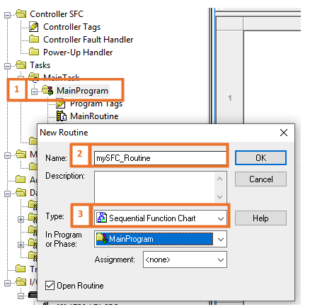
- Right Click on the Program in which the routine needs to be created.
- Type in a routine name.
- Select from the drop-down and select Sequential Function Chart.
After creating and opening the new routine, the following development environment is displayed.
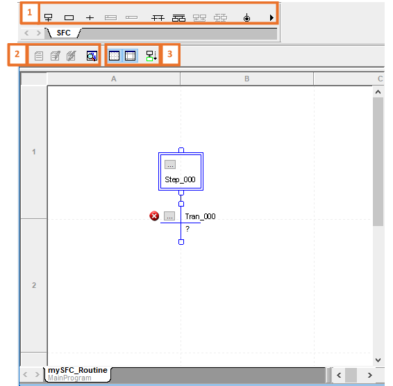
Graphical SFC elements are placed in the drawing space. This space has a grid structure in a spreadsheet like style, as can clearly be seen by the column (A, B, …) and row (1, 2, …) markers. The icons around the drawing space also change to accommodate the SFC environment:
- The SFC Element Toolbar is displayed.
- The views available can be changed here between Original View, Pending Edits View, Test Edits View and Routine Overview.
- The Grid and Sheet boundaries can be toggled between Show and Hide respectively. The Auto-Scroll feature, which when enabled allows the SFC routine to automatically scroll to the active step, can either be enabled or disabled.
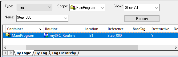
Interestingly, when cross-referencing a tag used in a Sequential Function Chart, the location will be shown according to the grid structure where it is found.
Fundamental Sequential Function Chart Elements
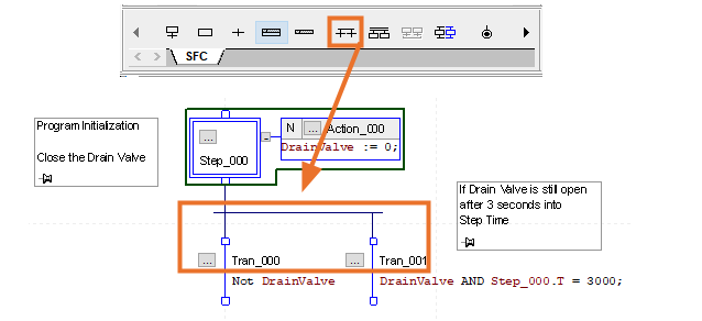
As briefly stated, the fundamental elements in Sequential Function Charts are Steps and Transitions. A step is a phase or part of the sequence that has an action or actions that must be carried out before continuing to the next. Each step uses a tag that has the ‘SFC_STEP’ data type structure.
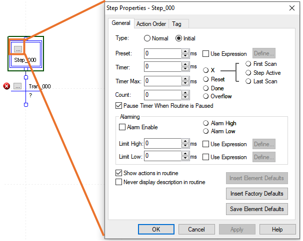
When opening the Step’s properties, configurable parameters are exposed that are linked to the members of the step’s data structure (For example, the Preset can be used outside this window by using Step_000.PRE). As can be seen by examining this window, every step among all its other features has a Timer and Counter dedicated to its structure, making the step data type very versatile.
By using right-click on the Step element, an Action associated with the step can be added.
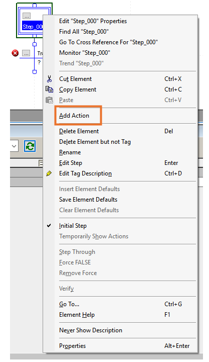

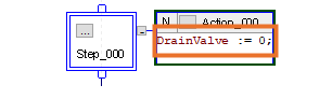
An action tag, of ‘SFC_ACTION’ data type structure, is automatically created. In the Action box, the instructions to be carried out by the associated step may be programmed. This logic is inserted by using Structured Text.
When the actions to be carried out on the specific step have been carried out, the normal flow of Sequential Function Chart will be to go to the transition element.

This is where specific conditions must be met to indicate that the step, together with its associated actions, have been successfully executed and thus the normal flow in the diagram may continue to the next element. The transition tag is a ‘BOOL’ data type, as it’s purpose is solely to indicate either a logical 0 / FALSE (flow may not continue) or logical 1 / TRUE (flow may continue) and is also programmed by making use of Structured Text.

More Sequential Function Chart Elements and branching techniques
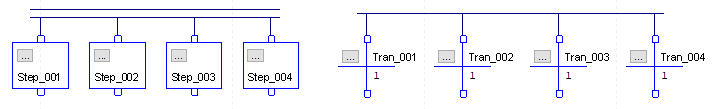
Thus far we have covered the basic Sequential Function Chart Elements, but it can clearly be seen from the SFC Toolbar, that there are a few variations that these elements may be used. In the event that two or more steps need to occur after a transition, a ‘Simultaneous Branch Diverge’ may be used.
The multiple step branching after a single transition is also known as Parallel Branching. After the transition’s condition is satisfied, both steps will occur simultaneously. Actions may be associated with them, as done previously, or even the timing component associated with the step’s data type structure may be used. It is possible to include multiple step actions in a single Action Element if the time in which it happens is not a concern but using multiple steps in some instances increases code legibility which in turn simplifies future fault finding or customization. While discussing fault finding simplification it is worth stating, that as with any coding in any programming language, it is always good practice to include comments to clarify the objective of the code and to keep clear track of where you are in the routine.
Just like a single transition may have multiple steps, a single step may have multiple transitions. A ‘Selection Branch Diverge’ may be used to do this.
The multiple transition branching after a single step is also known as Selective Branching. The steps following these transitions will not happen simultaneously, as is the case with a single transition. By examining the Sequential Function Chart, it can be seen that due to the different conditions that may trigger the transition to a logical TRUE state, it is not possible in this case for the following steps to be triggered at the same time.
Divergence in Sequential Function Charts, as explained in the previous examples, dealt with the splitting of a single path from either a step or transition into multiple branches to following steps or transitions.
It’s not only branch divergence that is possible in Sequential Function Charts, but also convergence. When necessary that two or more branches need to have a common following branch, like when two different transition conditions result in the same next step, the ‘Converge Selected SFC Elements’ may be used.
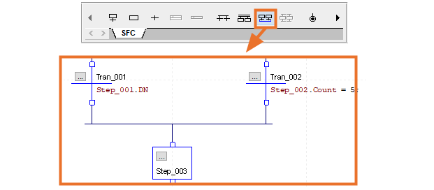
The conditions of the two transitions are different, but if either of these conditions should be TRUE, the respective transition will trigger the step irrespective of the other transition’s state. This specific convergence scenario is also known as General Convergence.
The other type of convergence happens when multiple steps use the same transition. The ‘Converge Selected SFC Elements’ may also be used to achieve this.
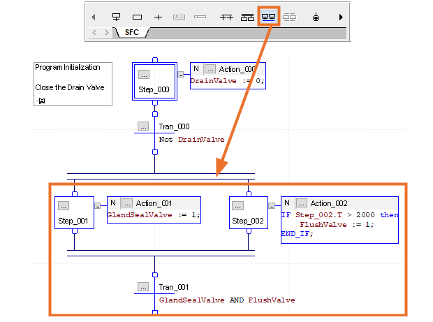
Even though the preceding steps to the converged transition branch have different actions, they both rely on this transition’s condition to result to logic TRUE before the flow may continue to the next step. This type of convergence is known as Simultaneous Convergence. It is worthwhile to mention that it is not necessary for the transition to look at the result of all steps as done in the above example, but may have any condition programmed in it as deemed necessary for the specific logic being programmed.
Depending on the process to be controlled by the program written in Sequential Function Chart, the flow of the program may be of the nature to be continuous. To achieve a continuous Sequential Function Chart, it is as easy as connecting the last transition in the diagram to the initial step, thus creating a loop. In some instances, this may not be the desired flow and stops may be used when and where necessary and may even be used multiple times throughout the routine.
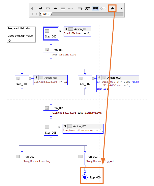
The ‘Add Stop’ may be used in the toolbar to add a ‘Stop’ Element. The tag associated with this element uses the ‘SFC_STOP’ data type structure. A stop may be used at the end of a Sequential Function Chart routine, or on a branch leg as in the example.
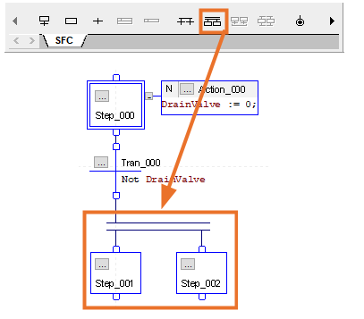
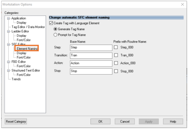
The norm for element creation, is that the element’s tag name is directly derived from the type of element added, appended with a suffix of the number used. This default automatic tag name generation may be customized to either fit the Engineer’s personal preferences, match the current routine’s purpose of logic, or disabled and rather prompt for tag name upon creation. This can be done by right-clicking in the open space in the editor and selecting ‘Options’.

Navigating to ‘Element Naming’ In the ‘Workstation Options Window’ that appears, the interface appears where customization of these defaults may be altered.
Advantages of Sequential Function Chart Programming
- The working of a physical process may be stripped into major parts and easily transformed into the major steps that must be programmed. This simplifies sequential implementation as well as fault finding.
- The use of Structured Text in combination with Sequential Function Chart elements, makes it a powerful language altogether.
- The flow diagram nature of the graphical implementation makes the program easy to follow during runtime.
- The data type structures of the elements lends itself to ease of manipulation.
Disadvantages of Sequential Function Chart Programming
- Programming language is mostly only suited for Sequential type processes.
- Although not a major disadvantage with the size of today’s controllers, the data type structures of the elements uses unnecessary memory, especially where most member tags are unused.
Conclusion
Learning an extra PLC programming language may seem like using a “different hammer to hit the same nail”, but in actual fact it equips you with an extra tool to use in your toolbox, that are in some instances better suited to solve a problem. We have gone through the basics here of the Sequential Function Chart environment. The fundamental elements have been described, common branching techniques to dictate the flow of the program, as well as the logical sequence of the order in which these elements will be called and used.
Take the time to go and look through the data structures of the elements. Identify all the members associated within the structure, as this will give you a clear sense of what is available to be used and manipulated. Think of previous programming that you have done in ladder, that may have been easier to write in a graphical programming language such as Sequential Function Charts. It is also strongly advised to ensure that there is a basic understanding of how to program using Structured Text.
