Siemens G120X/XA Drive Configuration with HMI Template

Introduction
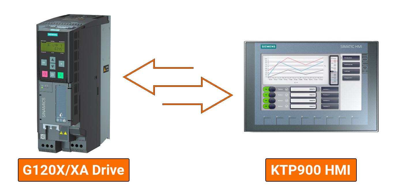
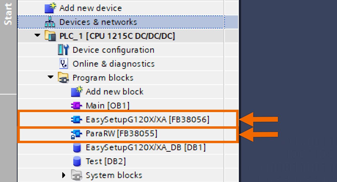
This tutorial presents a streamlined setup method for Siemens G120X/XA drives, designed to simplify commissioning and maintenance procedures. This program comprises two function blocks: 'ParaRW,' identified as FB38055, and 'EasySetupG120X/XA,' labeled as FB38056.
ParaRW (FB38055): This FB serves the purpose of interacting with drive parameters by employing acyclic communication methods for reading or writing. Among its features, it provides the functionality to restore drive parameters to their factory configuration and to write setup parameters collectively in batch form.
EasySetupG120X/XA (FB38056): Utilizing 'ParaRW' (FB38055), this FB can execute all functionalities integrated within FB38055. Additionally, it grants access to features such as PROFINET-enabled speed control and a user-program interface for executing drive commands and monitoring real-time status.
Prerequisites
What you will need to follow along with this tutorial:
- You need to install the TIA Portal software on your personal computer. Although this tutorial refers to version 18, rest assured that other versions of the TIA Portal will work just fine.
- You need to be familiar with installing the GSDML file of your desired servo drive in the TIA Portal.
- You are required to install SINAMICS StartDrive version 18 SP2.
Hardware Configuration
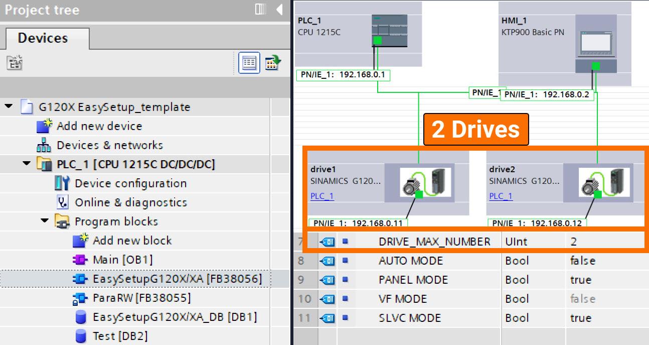
Within the framework of this application example, the hardware configuration encompasses the S7-1200 PLC, KTP 900 HMI, and G120X drive as its core components. While ensuring smooth communication, the PROFINET bus facilitates connections between the G120X, KTP 900 HMI, and S7-1200 PLC, with intricate configurations of IP addresses and device names presented in Figure 2.1.
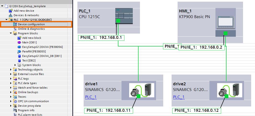
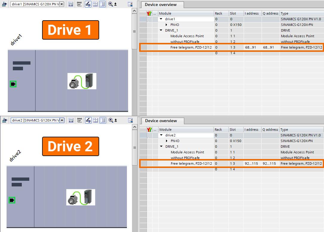
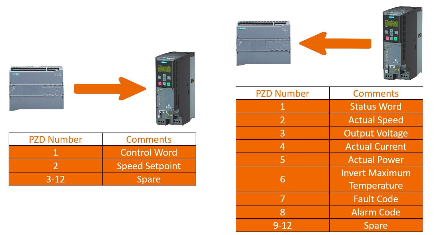
G120X units establish communication links with the PLC through free telegram 12/12, allowing for the exchange of critical data, such as speed setpoint, control word, actual values, and status word. Beyond its initial scope, this program caters to scenarios featuring more than two converters. Engineers must configure IP addresses and device names for supplementary converters and continue employing the free telegram 12/12 protocol.
PLC Programming Overview
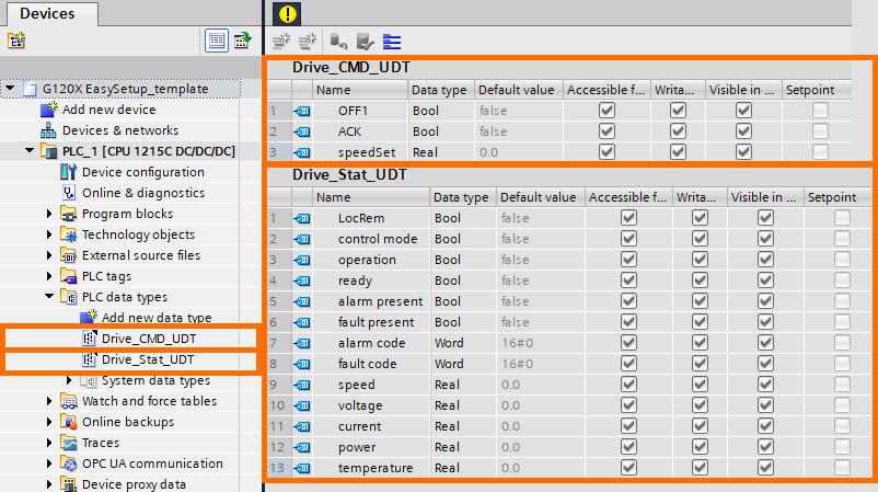
Within this template project, two distinct PLC data types have been established.
- Drive_CMD_UDT: Incorporating essential control commands of the drive like OFF1, ACK (Acknowledge commands), and SpeedSet (speed setpoint), this UDT offers proper control capabilities.
- Drive_Stat_UDT: Contained within this UDT are the actual values and the status word associated with the converter.
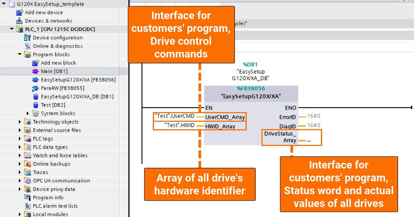
By utilizing EasySetupG120X/XA (FB38056) to invoke ParaRW (FB38055), engineers streamline their process, merely needing to call FB38056 in cyclic organization blocks such as OB1. Consequently, the PLC program achieves two crucial functions: 'Rapid Converter Setup' and 'PROFINET Speed Regulation.'
Rapid Converter Setup: Employing programmed instructions, the PLC autonomously conducts the reading and writing of all setup parameters, removing the necessity for manual input via 'Basic Operator Panel' or 'Intelligent Operator Panel' interfaces, thereby enhancing operational efficiency.
PROFINET Speed Regulation: Transmission of speed setpoint and control word from PLC to the drive is complemented by the reception of actual values and the status word, ensuring comprehensive communication.
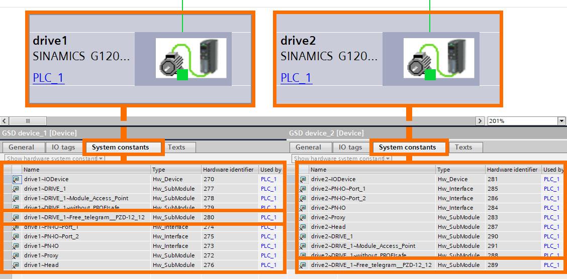
Ensure that the 'DRIVE_MAX_NUMBER' constant within the interface section of the 'EasySetupG120X/XA' function block correctly matches the total number of drives, then compile and call upon the block. Within the context of this application example, which encompasses two drives, the 'DRIVE_MAX_NUMBER' constant is accurately configured to reflect this count, fixed at 2.
Obtaining the drive's distinct hardware identifier entails navigating through the 'Device view,' selecting 'Properties,' and then accessing the 'System constants' section, as clearly outlined in Figure 3.4.
HMI Overview
Two HMI screens, labeled 'Monitoring' and 'Setup,' have been generated within the framework of this template project, tailored to specific functionalities.
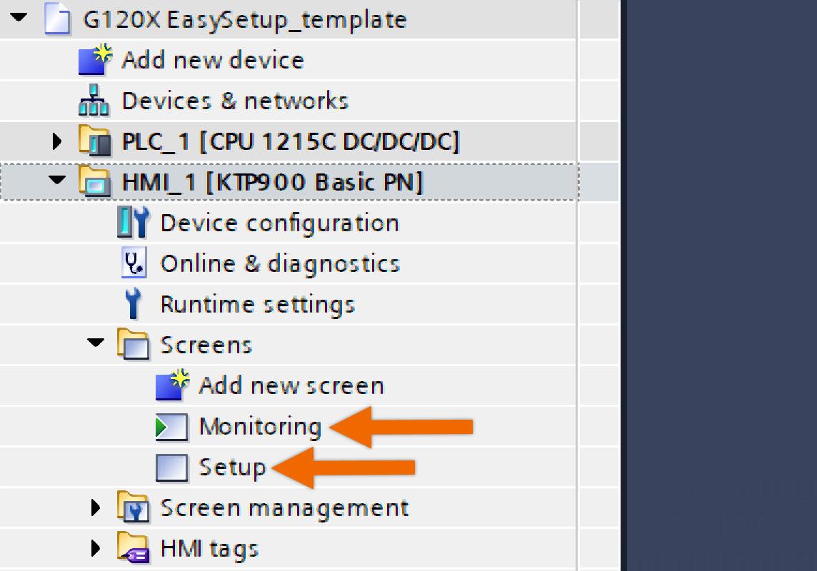
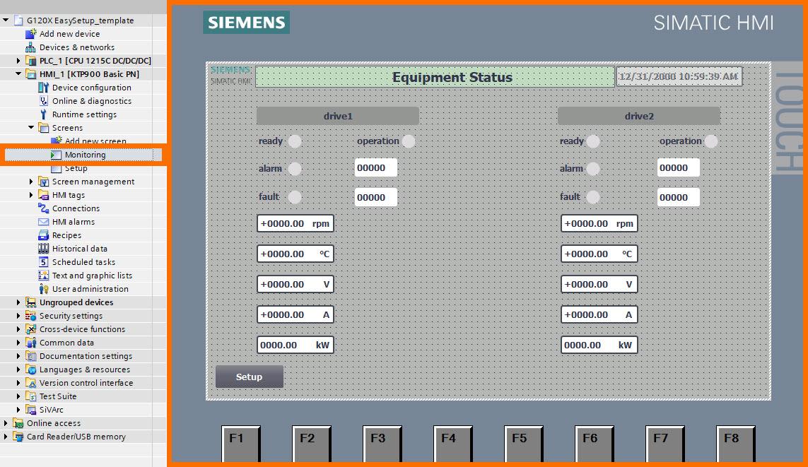
Monitoring Screen: Designed with monitoring in mind, this screen serves as a central hub, providing users with in-depth visibility into the status bits and real-time actual values across all drives.
Setup Screen: The focus of this screen is to streamline the commissioning process for the converter.
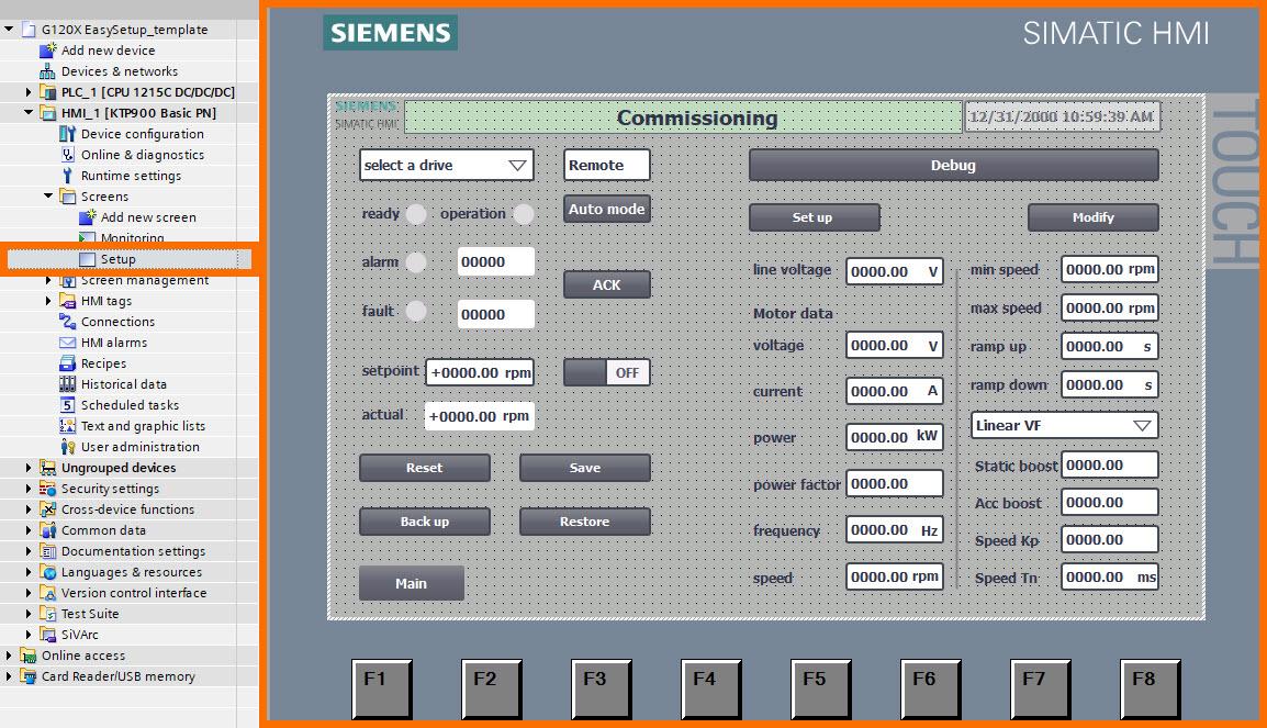
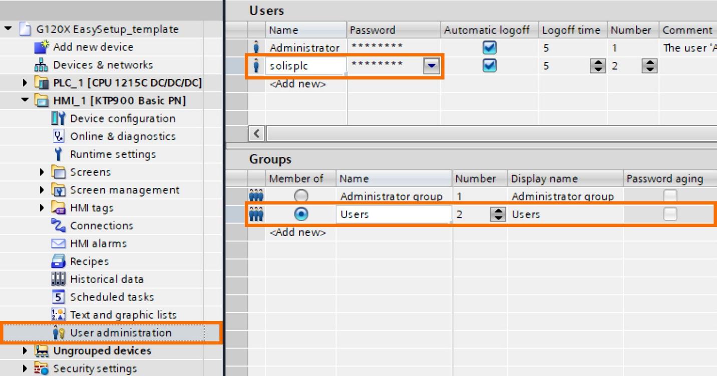
The default configuration takes the precautionary step of cloaking all setup function buttons to impede unauthorized access to drive parameters, fostering a secure operational environment. Display of these buttons is contingent upon the 'Debug' button being clicked and the correct user credentials entered, ensuring visibility is restricted to authorized users post-authentication.
The specified access credentials entail the username 'solisplc' and the associated password '123456'. Engineers are granted comprehensive authority to intricately modify the settings embedded within the 'User Administration' interface, as shown in Figure 4.4.
Operation Overview
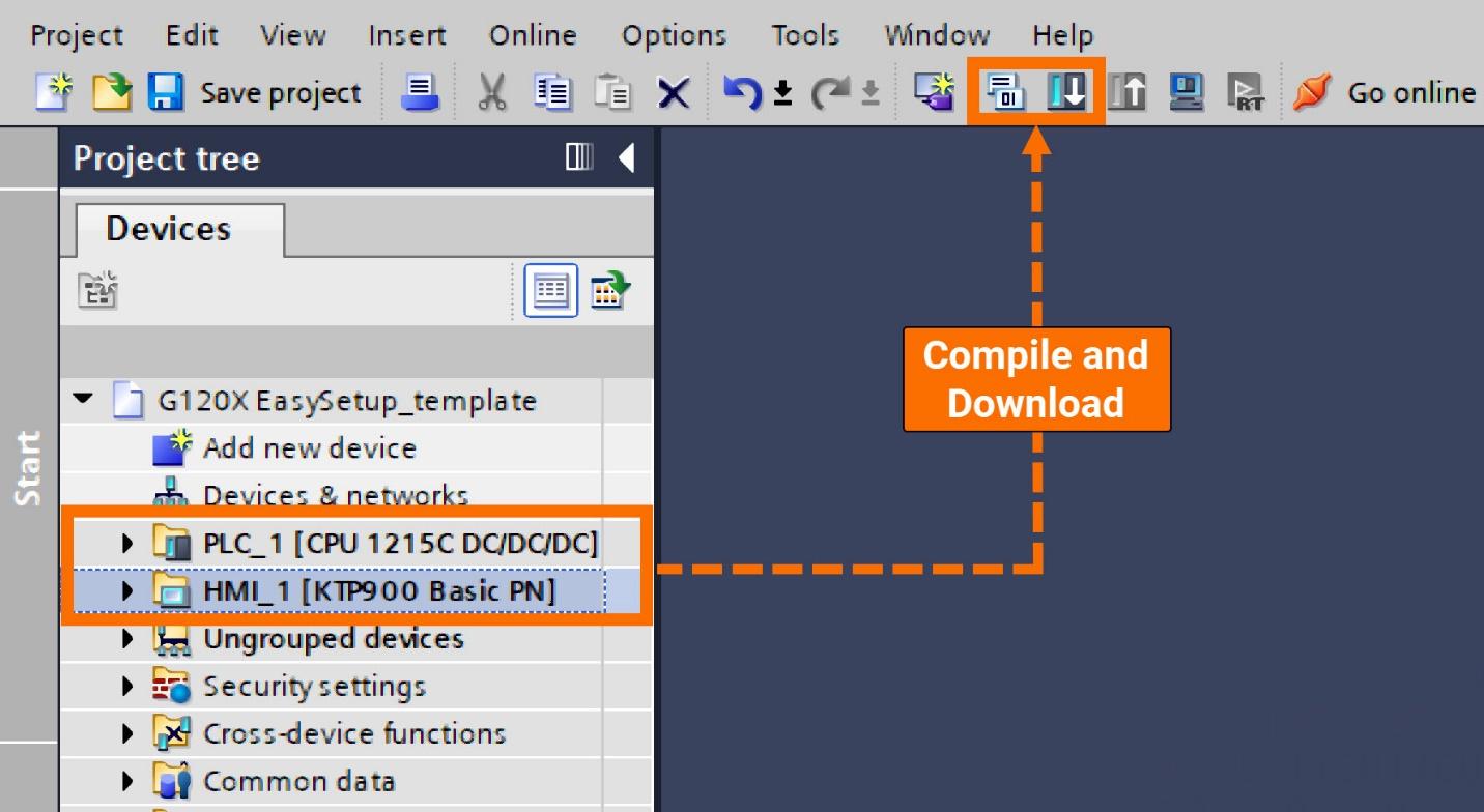
Before exploring the operation segment in-depth, it is imperative to fulfill two primary prerequisites: confirming the accurate configuration of IP addresses and device names for all drives and successfully downloading this project onto the PLC and HMI.
Let's enable the display of setup function buttons. Launch the process by clicking the 'Debug' button, and proceed to enter the requisite password and username.
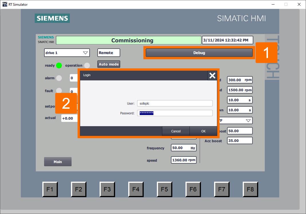
Clicking the 'Debug' button once more will result in the appearance of all setup function buttons.
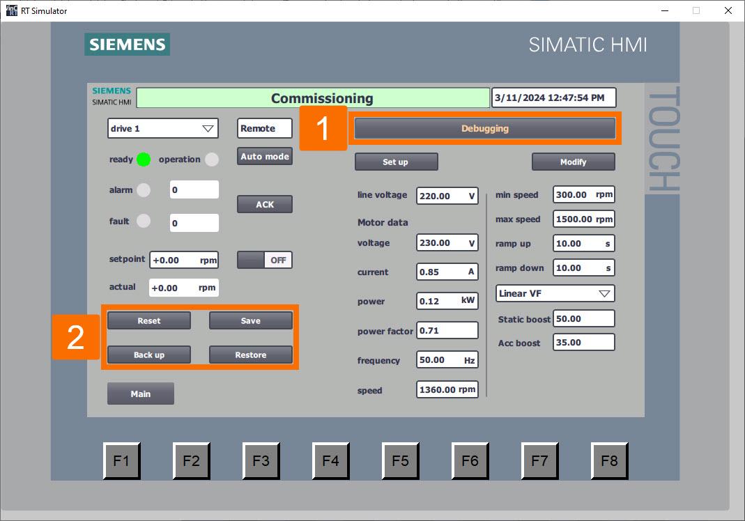
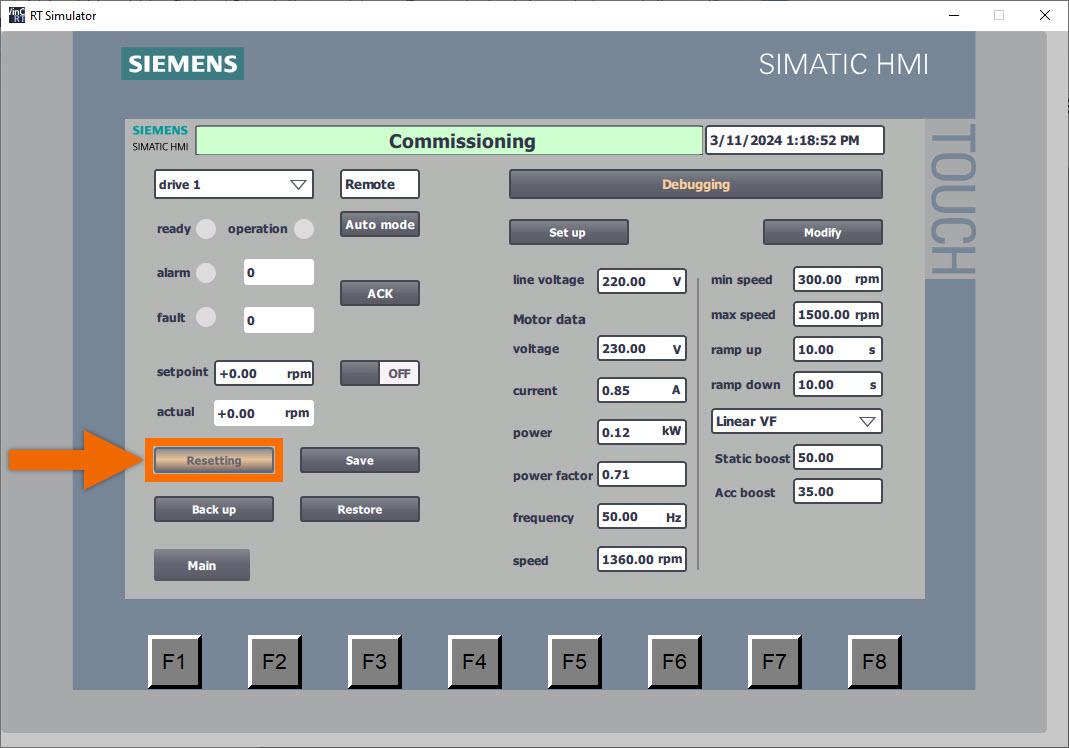
Proceed with resetting the drive parameters to their original factory configuration. Engage the converter's factory setting restoration process by clicking the 'Reset' button to initiate the operation. Throughout this operation, the button will visually indicate 'Resetting,' with the background shifting to an orange hue and intermittently flashing to signify ongoing activity.
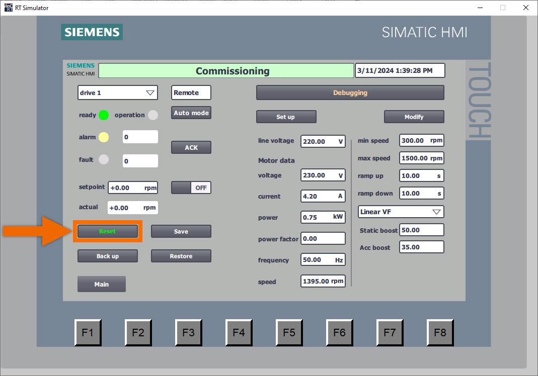
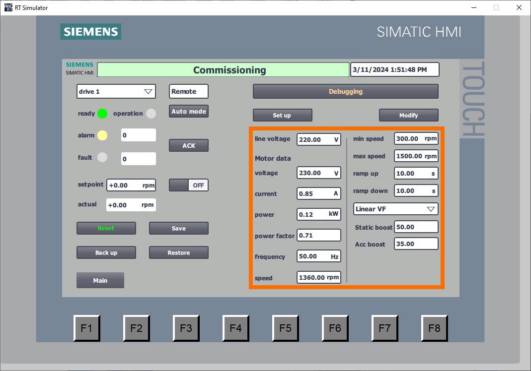
Once the reset process for all parameters is complete, the button will show 'Reset,' and the color of the text will transition to green. In addition, the HMI panel extends its display to include the default parameter setting of the converter.
Let's undertake the task of batch-writing setup parameters. Ensure all values of setup parameters are meticulously entered via the HMI panel interface, addressing crucial variables such as motor data, voltage of the line, control mode of the drive, and ramp time. The remaining customized parameters have been intricately configured within the function block, sparing the user from the necessity of manual input through the HMI panel interface.
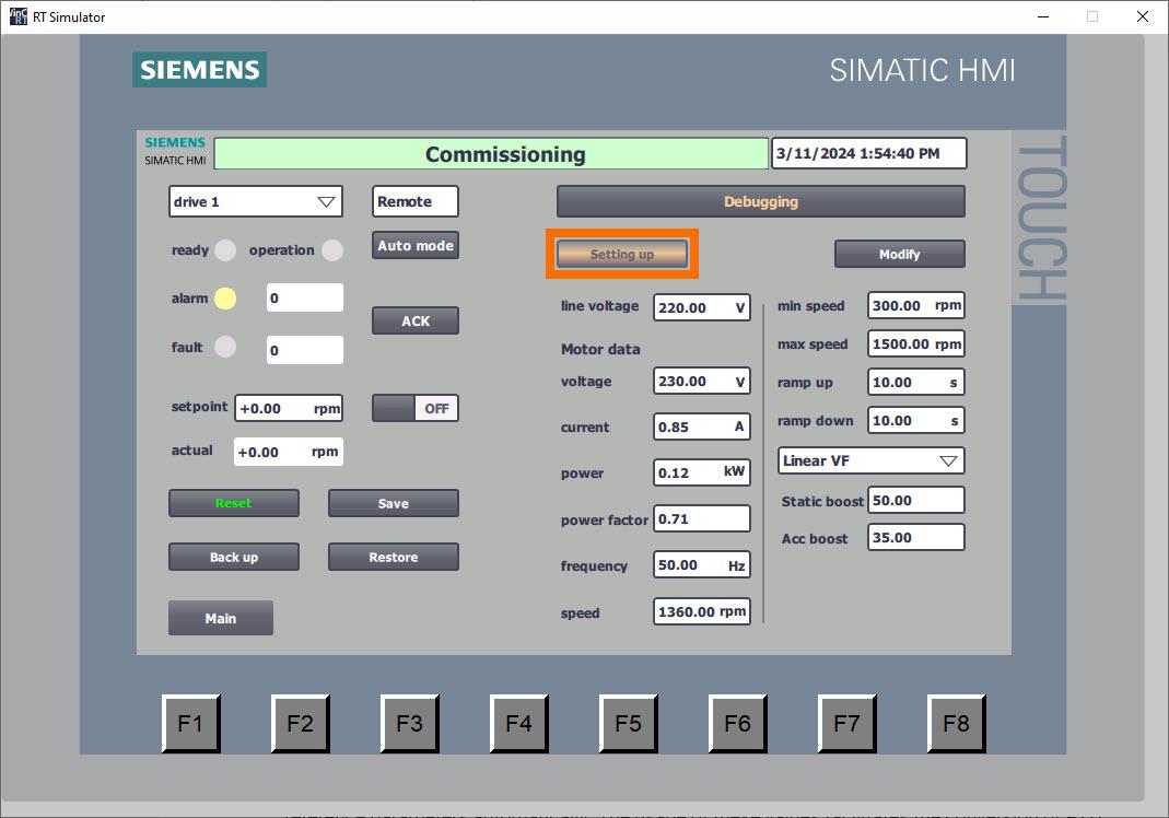
Trigger the PLC to begin batch writing of parameters by pressing the 'Setup' button. Throughout this operation, the button will visually indicate 'Setting up,' with the background shifting to an orange hue and intermittently flashing to signify ongoing activity.
Following the writing of all parameters, the button transitions to the 'Set up' display, while the color of the text elegantly changes to a vibrant green hue. The automatic activation of motor standstill identification results in the 'A07991' notification being displayed.
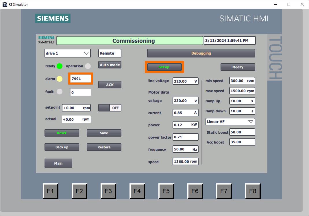
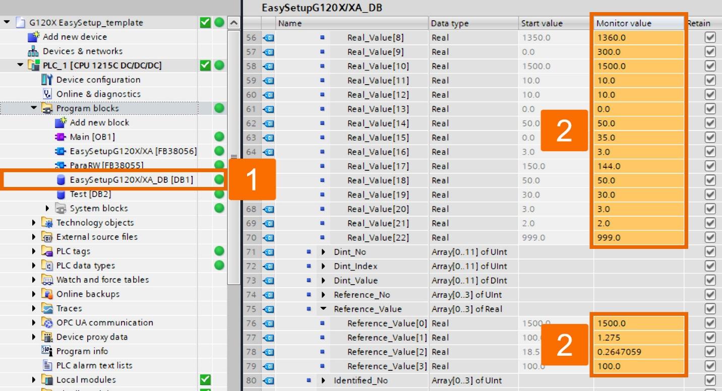
Following the completion of parameter writing, the PLC seamlessly engages in the retrieval of reference parameters automatically. The usage of these values facilitates the conversion of PZD data into actual values, incorporating the appropriate physical units.
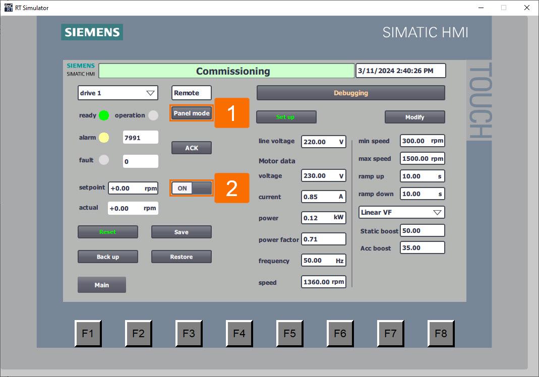
At this moment, employ the HMI panel controls to implement standstill identification. Following parameter setup, engagement of 'Panel mode' is possible by clicking the 'Auto mode' button, denoting the switch to HMI panel control of the converter. Activate the converter by clicking the 'ON/OFF' button; this triggers motor standstill identification.
It's time to adjust application parameters collectively in batch mode. Via the HMI panel interface, input updated values for application parameters, covering elements such as limits of the speed, drive control mode, ramp time, and other relevant variables.
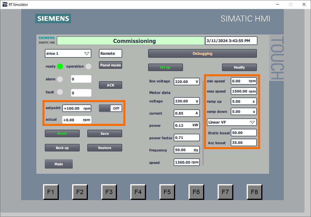
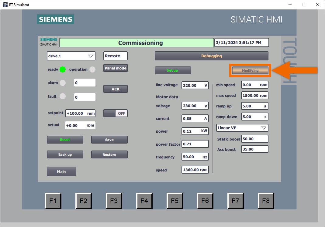
Depress the 'Modify' button to initiate the batch-writing process for all application parameters. Throughout this operation, the button will visually indicate 'Modifying,' with the background shifting to an orange hue and intermittently flashing to signify ongoing activity.
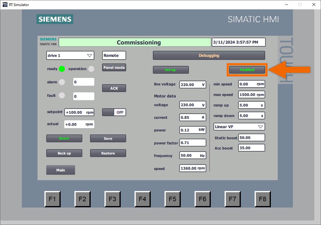
Following the writing of all parameters, the button transitions to the 'Modified' display, while the color of the text elegantly changes to a vibrant green hue.
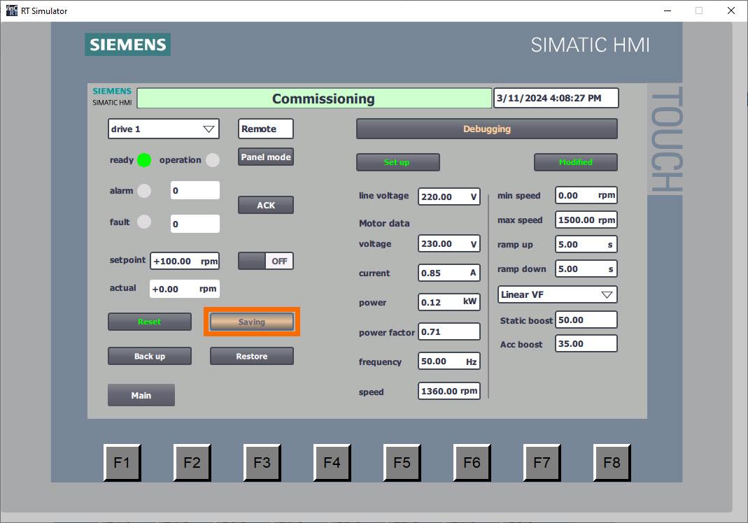
Upon completion of the commissioning process for a converter, it becomes imperative to ensure the permanent retention of all parameters to prevent their loss in the event of a power interruption. Select the 'Save' button to ensure the permanent storage of all parameters. Throughout this operation, the button will visually indicate 'Saving,' with the background shifting to an orange hue and intermittently flashing to signify ongoing activity.
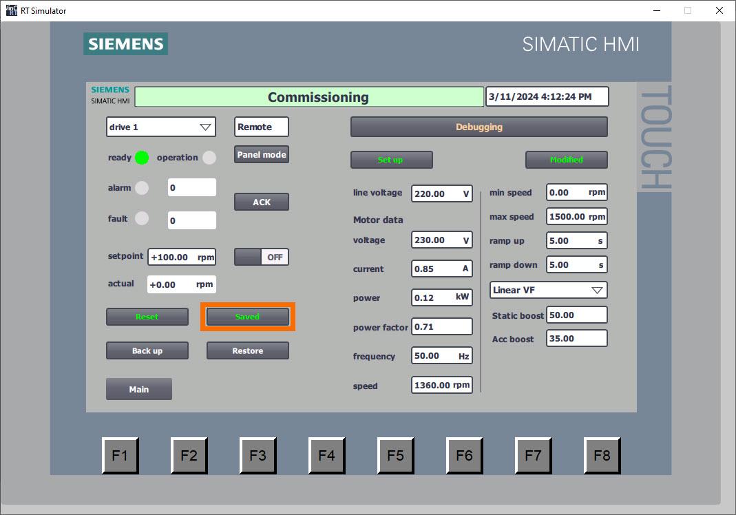
Upon completion of parameter storage, the button indicates 'Saved' and transitions its text color to green, signifying successful preservation.
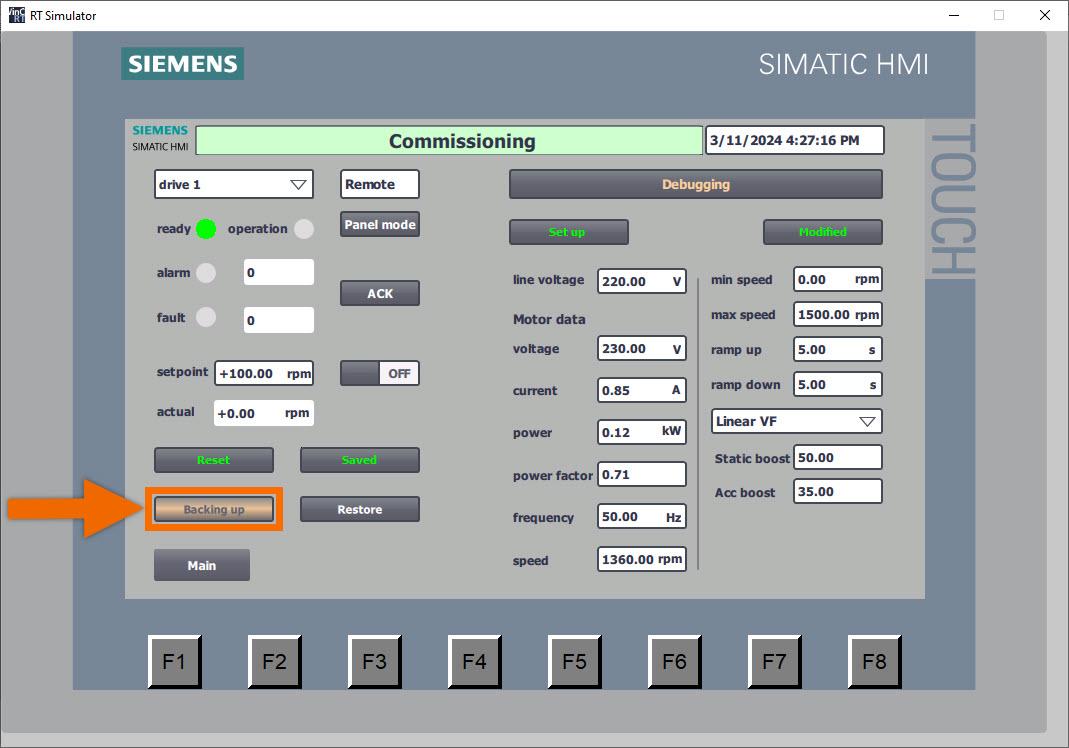
Press the 'Backup' button to initiate the PLC's backup of drive parameters. Throughout this operation, the button will visually indicate 'Backing up,' with the background shifting to an orange hue and intermittently flashing to signify ongoing activity.
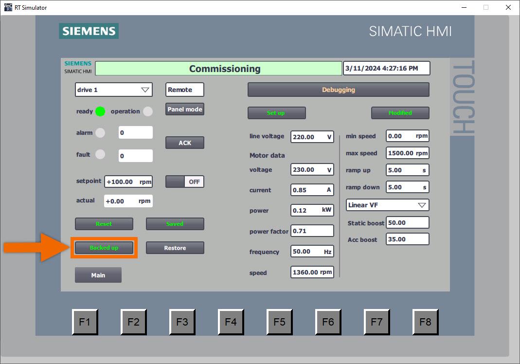
Upon completion of parameter backup, the button indicates 'Backed up' and transitions its text color to green, signifying successful preservation.
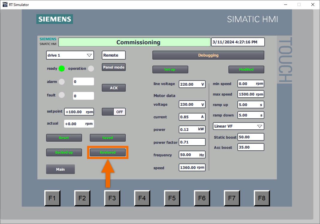
Now is the ideal moment to begin restoring parameters from the PLC. Ensure the converter is configured accurately with the appropriate IP address and device name. Press the 'Restore Para' button. Hold on until the button indicates the 'Restored' status. Engineers benefit from the remarkable convenience of this function in scenarios such as debugging similar devices or substituting new drives, enabling swift adjustment of all parameters.
Conclusion
In conclusion, you learned a simplified setup method for Siemens G120X/XA drives using two function blocks: 'ParaRW' (FB38055) and 'EasySetupG120X/XA' (FB38056). These blocks facilitate interaction with drive parameters and offer features like restoring factory configurations and batch-writing setup parameters. Integration of these blocks into PLC programming enables rapid converter setup and PROFINET speed regulation, enhancing operational efficiency. Additionally, the tutorial covers configuring parameters through the HMI panel, providing a comprehensive guide for efficient commissioning and maintenance of Siemens G120X/XA drives.
